EP0226089A1 - Automatische Bilddichtesteuerungsvorrichtung - Google Patents
Automatische Bilddichtesteuerungsvorrichtung Download PDFInfo
- Publication number
- EP0226089A1 EP0226089A1 EP86116473A EP86116473A EP0226089A1 EP 0226089 A1 EP0226089 A1 EP 0226089A1 EP 86116473 A EP86116473 A EP 86116473A EP 86116473 A EP86116473 A EP 86116473A EP 0226089 A1 EP0226089 A1 EP 0226089A1
- Authority
- EP
- European Patent Office
- Prior art keywords
- density
- original
- read
- control
- image density
- Prior art date
- Legal status (The legal status is an assumption and is not a legal conclusion. Google has not performed a legal analysis and makes no representation as to the accuracy of the status listed.)
- Withdrawn
Links
- 230000004044 response Effects 0.000 abstract description 4
- 108091008695 photoreceptors Proteins 0.000 description 14
- 238000010586 diagram Methods 0.000 description 6
- 238000000034 method Methods 0.000 description 6
- 239000007787 solid Substances 0.000 description 4
- 239000011521 glass Substances 0.000 description 3
- 230000003287 optical effect Effects 0.000 description 3
- 238000000926 separation method Methods 0.000 description 3
- 230000003068 static effect Effects 0.000 description 3
- 230000001447 compensatory effect Effects 0.000 description 2
- 230000001276 controlling effect Effects 0.000 description 2
- BUGBHKTXTAQXES-UHFFFAOYSA-N Selenium Chemical compound [Se] BUGBHKTXTAQXES-UHFFFAOYSA-N 0.000 description 1
- 230000002411 adverse Effects 0.000 description 1
- 230000000052 comparative effect Effects 0.000 description 1
- 230000000994 depressogenic effect Effects 0.000 description 1
- 230000000630 rising effect Effects 0.000 description 1
- 229910052711 selenium Inorganic materials 0.000 description 1
- 239000011669 selenium Substances 0.000 description 1
- 208000024891 symptom Diseases 0.000 description 1
- 229910052714 tellurium Inorganic materials 0.000 description 1
- 229940074389 tellurium Drugs 0.000 description 1
- PORWMNRCUJJQNO-UHFFFAOYSA-N tellurium atom Chemical compound [Te] PORWMNRCUJJQNO-UHFFFAOYSA-N 0.000 description 1
Images


Classifications
-
- G—PHYSICS
- G03—PHOTOGRAPHY; CINEMATOGRAPHY; ANALOGOUS TECHNIQUES USING WAVES OTHER THAN OPTICAL WAVES; ELECTROGRAPHY; HOLOGRAPHY
- G03G—ELECTROGRAPHY; ELECTROPHOTOGRAPHY; MAGNETOGRAPHY
- G03G15/00—Apparatus for electrographic processes using a charge pattern
- G03G15/50—Machine control of apparatus for electrographic processes using a charge pattern, e.g. regulating differents parts of the machine, multimode copiers, microprocessor control
- G03G15/5025—Machine control of apparatus for electrographic processes using a charge pattern, e.g. regulating differents parts of the machine, multimode copiers, microprocessor control by measuring the original characteristics, e.g. contrast, density
Definitions
- the present invention relates to an automatic image density control device, more particularly, to an automatic image density control device capable of adequately controlling light intensity output from a light source illuminating the original or development bias signal applied to a developing device in accordance with the image density of the original.
- any of conventional image generating devices incorporates an automatic image density control device for generating images having adequate density in accordance with the density of the original.
- conventional automatic image control density devices are grouped into either the "pre-scan” type or the "real-time” type.
- the pre-scan type automatic image density control device scans the original before generating picture images so that an optimum power to be supplied to the light source or an optimum development bias can be provided to deal with the original's image having the weakest density.
- the real-time type automatic image density control device reads the image density of the original in process of simultaneously generating picture images so that an optimum power to be supplied to the light source or an optimum development bias can be provided to deal with the original's image density being present in every moment.
- the pre-scan type automatic image density control device since the device needs to precisely scan the original before generating picture images, a longer period of time is needed for generating the first picture image corresponding to the original.
- the real-time type automatic image density control device since this device varies either the power to be fed to the light source or the development bias in response to the image density of the original at every scanning timing, it merely needs to execute the scanning operation once without spending a longer period of time for generating the first picture image corresponding to the original.
- the primary object of the present invention is to effectively save time needed for generating the first picture image corresponding to the original.
- Another object of the present invention is to secure deeplyly prevent erased portions from taking place even when solid portion is present in the image density reading regeon of the original.
- the automatic image density control device reflecting the preferred embodiments of the present invention incorporates means for reading the density of the original, memory means, comparison means, and control means, respectively.
- Memory means stores data related to the weakest density of the original thus far read.
- Comparison means compares the read-out density of the original to that is stored in memory means.
- Control means outputs control signals in response to the read-out density of the original on receipt of comparative signal from comparison means identifying that the read-out density of the original is weaker.
- Control means may supply control signals either to light source or developing device.
- the automatic image density control device related to the invention having the constitution mentioned above allows means for reading the density of the original to sequentially read the density of the original, and then activates comparison means to compare the weakest density of the original from the preceding read-out density to the newly read out density of the original, and if comparison means outputs a comparison signal identifying that the newly read out density is weaker than the preceding density, the system causes control means to vary control signals to be applied to either light source or developing device so that image can eventually be provided with an optimum density.
- FIG. 1 is the simplified schematic diagram of the electrophotographic copying machine incorporating one of the preferred embodiments of the present invention, which is provided with a light source S illuminating the original D placed on the upper surface of a contact glass 1, mirrors 2 through 4 a lens 5, and a mirror 6 which respectively guide light reflected from the original D to the photoreceptive drum 7, a static charger 8, a developing device 9, a transfer charger 10, a separation charger 11, a cleaner 12, and a resist roller 13.
- the copying machine is provided with an optical sensor 14 in a position close to the lens 5.
- Signals output from the optical sensor 14 are firstly amplified by an amplifier 15, which are then A/D converted by an A/D converter 15′.
- the A/D converted signals are then applied to a control circuit 16 which is substantially comparison means.
- Signals output from the control circuit 16 are then converted into analog signals by the D/A converter 17, and in response to these analog signals, a power supply circuit 18 applies drive voltage to the light source S.
- the electronic system of this copying machine is provided with a memory 19 for allowing the control circuit 16 to write and read data signals into and from it.
- FIG. 2 is the operation flowchart describing the automatic image density control operation related to the present invention.
- the automatic image density control system related to the present invention firstly remains in stand-by state until the print key is manually depressed in step 1.
- step 2 the control system sets a specific value which is substantially the initially read light amount corresponding to a proper shade between white and black.
- step 3 the optical sensor 14 reads the amount of light reflected from the original.
- step 4 the control system decides whether the amount of light reflected from the original is greater than the read-out light amount (maximum value of the light amount thus far read) stored in the memory 19, or not.
- control system varies the initially set read-out light amount in proportion to the newly read-out light amount during step 5.
- step 6 the control system replaces the value stored in the memory 19 with the newly read-out value.
- step 7 the control system feeds power corresponding to the newly set value to the light source S.
- step 4 determines whether the amount of light reflected from the original is less than the read-out light amount stored in the memory 19, then the control system feeds power corresponding to the set value to the light source S in step 7.
- the control system decides during step 8 whether the scanning operation throughout the entire areas of the original is completed, or not. If it is not yet completed, the control system repeatedly executes deciding and processing which are to be done from steps 3 and so on. If it is already completed, the control system turns the light source S off during step 9 to complete the entire copying operations.
- the control system doesn't vary the power being supplied to the light source S.
- the control system renews the content of the memory 19, and at the same time, it varies the power being supplied to the light source S in proportion to the read-out light amount. This allows the control system to effectively implement real-time processes and securely prevent erasure symptom from occurrence.
- control system effectively controls the power to be applied to the light source S in accordance with the read-out density of the original.
- control system it is also possible for the control system to automatically control the image density by varying development bias signal being applied to the developing device 9 in the same way as above.
- control system it is also possible for the control system to set the amount of light to be initially read-out by reading the amount of light reflected from the reference board set in front of the position for starting the control of the image density of the original.
- FIG. 6 is the simplified schematic diagram denoting the internal constitution of the electrophotographic copying machine having the constitution other than the above.
- This machine is provided with an exposure lamp S for illuminating the original D placed on a contact glass 1 and a photoreceptive sensor 14 receiving part of light reflected from the original D.
- the machine is provided with a photoreceptor drum 7 (containing selenium tellurium) which is capable of rotating itself and installed to a position below the contact glass 1.
- This machine is also provided with a static charger 8, a developing device 9, a transfer charger 10, a separation charger 11, a cleaner 12, and a thermistor 21, which are installed in the periphery of the photoreceptor drum 7 in the order mentioned above.
- the copying paper is guided to between the photoreceptor drum 7 and the transfer charger 10 via a copying paper conveying part 22, and then, after causing the separation charger 11 to peel the copying paper from the photoreceptor drum 7, the copying paper conveying part 22 conveys the copying paper to the fixing device 25.
- FIG. 3 is the simplified block diagram of another preferred embodiment of the automatic image density control device related to the present invention.
- Signals output from the photoreceptive sensor 14 and the thermistor 21 are respectively applied to a microcomputer 23 through an A/D converter and an I/O interface which are not shown.
- Control signal from the microcomputer 23 is applied to an exposure lamp lighting circuit 24 through an I/O interface and a D/A converter which are not shown, and then voltage signal from the exposure lamp lighting circuit 24 is applied to the exposure lamp S.
- FIG. 4 is the operation flowchart describing operations of the automatic image density control device shown in FIG. 3.
- the control system not only controls the image density in proportion to the density of the original, but it also precisely controls the image density by properly compensating for the temperature characteristic of the photoreceptor drum itself. More particularly, since temperature characteristic of the selenium-applied photoreceptor drum is not linear, application of linear temperature compensation (see FIG.
- the copying system related to the present invention improves the quality of image of the copied paper by properly compensating for temperature in a specific area where temperature compensation is needed, while deleting compensatory process in such an area where no temperature compensation is necessary.
- the control system After completing provision of the initial mode and warm-up process in a step not shown, the control system supplies the predetermined voltage to the exposure lamp S during step 1 so that the original can be illuminated.
- the photoreceptive sensor 14 directly detects part of light reflected from the original D.
- the thermistor 21 detects ambience temperature of the photoreceptor drum 7.
- the control system decides whether temperature T°C detected by the thermistor 21 is within the predetermined range of temperature (Tl°C ⁇ T°C ⁇ T2°C), or not.
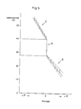
- step 4 If it is identified during step 4 that temperature T°C exactly matches T1°C ⁇ T°C ⁇ T2°C, when the next step 5 is entered, as shown by area A of FIG. 5, the control system varies voltage to be supplied to the exposure lamp S in accordance with the density of the original without executing compensatory process related to temperature at all. Concretely, the control system executes those operations which are identical to those which are shown in FIG. 2. Next, when step 10 is entered, the control system allows the copying operation to be done by applying a specific voltage varied during step 5, thus eventually producing a copied object containing an optimum density.
- step 4 If it is identified during step 4 that temperature T°C detected by the thermistor 21 is T°C ⁇ T1°C, the control system varies voltage being supplied to the exposure lamp S in accordance with the density of the original during step 6. Concretely, the control system executes those operations which are identical to those which are shown in the operation flowchart of FIG. 2. Next, when step 7 is entered, as shown in area B of FIG. 5, the control system varies the voltage being applied to the exposure lamp S in order that temperature range can be expanded to allow compensation for the identical amount to be implemented as temperature lowers. Then, the control system executes operations specified by step 10.
- step 4 determines whether temperature detected by the thermistor 21 is T2°C ⁇ T°C.
- the control system varies the voltage being applied to the exposure lamp S in accordance with the density of the original while step 8 is underway. Concretely, the control system executes those operations which are identical to those which are shown in operation flowchart of FIG. 2.
- step 9 is entered, as shown in area C of FIG. 5, the control system varies the voltage being applied to the exposure lamp S in order that temperature range (where compensation for the identical amount can be provided) without adversely being affected by rising temperature. Then, the control system executes operations specified by step 10.
- temperature T1°C and T2°C respectively correspond to 28°C and 40°C in FIG. 5.
- the photoreceptor drum 7 bears 20°C through 25°C of temperature, and thus, there is no need of compensating for temperature.
- temperature may vary by order of several centigrades depending on the kind of the photoreceptor drum being used and the arrangement of component parts and members in the copying machine, and therefore, it is desirable to allow temperature T1°C and T2°C to be variable in each copying machine.
- the copying machine can produce satisfactory copied-papers having an optimum density by controlling voltage to be supplied to the exposure lamp S in accordance with the density of the original.
- the control system controls voltage being applied to the exposure lamp S in accordance with the density of the original, and at the same time, it also controls voltage being applied to the exposure lamp S in accordance with temperature detected by the thermistor 21 to allow the copying machine to eventually produce ideal copied papers having an optimum density.
- the preferred embodiment shown in FIG. 3 controls voltage being applied to the exposure lamp S.
- the control system can also control development bias signal to be applied to the developing device 9.
- the control system it is possible for the control system to allow the surface potential sensor to detect the density of the original instead of allowing the photoreceptive sensor 14 to detect the density of the original.
- the copying machine incorporating the automatic image density control device related to the present invention can install the thermistor 21 in a position other than between the static charger 8 and the cleaner 12.
Landscapes
- Engineering & Computer Science (AREA)
- Microelectronics & Electronic Packaging (AREA)
- Physics & Mathematics (AREA)
- General Physics & Mathematics (AREA)
- Control Or Security For Electrophotography (AREA)
- Exposure Or Original Feeding In Electrophotography (AREA)
- Control Of Exposure In Printing And Copying (AREA)
- Developing For Electrophotography (AREA)
Applications Claiming Priority (2)
| Application Number | Priority Date | Filing Date | Title |
|---|---|---|---|
| JP270526/85 | 1985-11-29 | ||
| JP60270526A JPS62129870A (ja) | 1985-11-29 | 1985-11-29 | 自動露光装置 |
Publications (1)
| Publication Number | Publication Date |
|---|---|
| EP0226089A1 true EP0226089A1 (de) | 1987-06-24 |
Family
ID=17487446
Family Applications (1)
| Application Number | Title | Priority Date | Filing Date |
|---|---|---|---|
| EP86116473A Withdrawn EP0226089A1 (de) | 1985-11-29 | 1986-11-27 | Automatische Bilddichtesteuerungsvorrichtung |
Country Status (2)
| Country | Link |
|---|---|
| EP (1) | EP0226089A1 (de) |
| JP (1) | JPS62129870A (de) |
Families Citing this family (1)
| Publication number | Priority date | Publication date | Assignee | Title |
|---|---|---|---|---|
| US6912366B1 (en) * | 1999-08-31 | 2005-06-28 | Canon Kabushiki Kaisha | Image forming apparatus comprising means for detecting an amount of developer contained in a developer container, a memory for storing the amount detected by the detecting means, and control means for updating the information stored in the memory |
Citations (1)
| Publication number | Priority date | Publication date | Assignee | Title |
|---|---|---|---|---|
| DE3325461A1 (de) * | 1982-07-15 | 1984-01-19 | Canon K.K., Tokyo | Bilderzeugungseinrichtung |
-
1985
- 1985-11-29 JP JP60270526A patent/JPS62129870A/ja active Pending
-
1986
- 1986-11-27 EP EP86116473A patent/EP0226089A1/de not_active Withdrawn
Patent Citations (1)
| Publication number | Priority date | Publication date | Assignee | Title |
|---|---|---|---|---|
| DE3325461A1 (de) * | 1982-07-15 | 1984-01-19 | Canon K.K., Tokyo | Bilderzeugungseinrichtung |
Non-Patent Citations (6)
| Title |
|---|
| IBM TECHNICAL DISCLOSURE BULLETIN, vol. 21, no. 9, February 1979, pages 3546-3547; A.J. DATTILO et al.: "Variable intensity illumination scanner calibration system" * |
| PATENT ABSTRACTS OF JAPAN, vol. 9, no. 127 (P-360)[1850], 31st May 1985; & JP-A-60 010 267 (CANON) 19-01-1985 * |
| PATENT ABSTRACTS OF JAPAN, vol. 9, no. 177 (P-375)[1900], 23rd July 1985; (MATSUSHITA DENKI SANGYO) 20-03-1985 * |
| PATENT ABSTRACTS OF JAPAN, vol. 9, no. 243 (P-392)]1966], 30th September 1985; & JP-A-60 095 453 (CANON) 28-05-1985 * |
| PATENT ABSTRACTS OF JAPAN, vol. 9, no. 262 (P-398)[1985], 19th October 1985; & JP-A-60 112 072 (MATSUSHITA DENKI SANGYO) 18-06-1985 * |
| PATENT ABSTRACTS OF JAPAN, vol. 9, no. 269 (P-400)[1992], 26th October 1985; & JP-A-60 117 263 (MITA KOGYO) 24-06-1985 * |
Also Published As
| Publication number | Publication date |
|---|---|
| JPS62129870A (ja) | 1987-06-12 |
Similar Documents
| Publication | Publication Date | Title |
|---|---|---|
| US5857131A (en) | Image forming condition control device and method for an image forming apparatus | |
| US6240263B1 (en) | Flicker suppression device in electronic equipment | |
| US7289249B2 (en) | Image scanner for use in image forming apparatus | |
| US4763200A (en) | Image output apparatus | |
| US7283285B2 (en) | Image forming apparatus and method of controlling the apparatus | |
| EP0226089A1 (de) | Automatische Bilddichtesteuerungsvorrichtung | |
| US5107300A (en) | Image forming apparatus including means for controlling the amount of light exposure | |
| GB2138582A (en) | Image Reproducing Apparatus | |
| JPS60184240A (ja) | 画像形成装置 | |
| US4831418A (en) | Exposure control device of copying machine | |
| JPH0418304B2 (de) | ||
| US5423512A (en) | Mirror smudge detecting apparatus for an image forming apparatus | |
| JP3002278B2 (ja) | デジタル画像形成装置 | |
| JPS62258481A (ja) | 画像形成装置 | |
| US6734999B1 (en) | Image forming apparatus and image forming method | |
| US5392097A (en) | Image processing apparatus | |
| JPS6232477A (ja) | 現像剤供給量制御方法 | |
| JP2555559B2 (ja) | 現像剤供給量制御方法 | |
| US5253014A (en) | Image forming apparatus including a controller for controlling image forming conditions in accordance with normalized differences in detected densities | |
| JPH0974467A (ja) | 画像形成装置及びその記録媒体の識別方法 | |
| US5790164A (en) | Image scanning and writing apparatus which uses different synchronizing signals for scanning and writing | |
| JPH11202564A (ja) | 画像形成装置 | |
| JPH09160314A (ja) | 画像形成装置 | |
| JPS59121075A (ja) | 画像形成装置 | |
| JP2973591B2 (ja) | 画像形成装置 |
Legal Events
| Date | Code | Title | Description |
|---|---|---|---|
| PUAI | Public reference made under article 153(3) epc to a published international application that has entered the european phase |
Free format text: ORIGINAL CODE: 0009012 |
|
| AK | Designated contracting states |
Kind code of ref document: A1 Designated state(s): DE FR GB NL |
|
| 17P | Request for examination filed |
Effective date: 19870923 |
|
| 17Q | First examination report despatched |
Effective date: 19890531 |
|
| STAA | Information on the status of an ep patent application or granted ep patent |
Free format text: STATUS: THE APPLICATION IS DEEMED TO BE WITHDRAWN |
|
| 18D | Application deemed to be withdrawn |
Effective date: 19890530 |
|
| RIN1 | Information on inventor provided before grant (corrected) |
Inventor name: KISHIMOTO, KEIICHI Inventor name: NAKAMARU, TORU Inventor name: MIZUDE, KAZUHIRO |