EP0226355A2 - Système de commande d'actionneur - Google Patents
Système de commande d'actionneur Download PDFInfo
- Publication number
- EP0226355A2 EP0226355A2 EP86309186A EP86309186A EP0226355A2 EP 0226355 A2 EP0226355 A2 EP 0226355A2 EP 86309186 A EP86309186 A EP 86309186A EP 86309186 A EP86309186 A EP 86309186A EP 0226355 A2 EP0226355 A2 EP 0226355A2
- Authority
- EP
- European Patent Office
- Prior art keywords
- actuator
- velocity
- seek
- trapezoidal
- seek stroke
- Prior art date
- Legal status (The legal status is an assumption and is not a legal conclusion. Google has not performed a legal analysis and makes no representation as to the accuracy of the status listed.)
- Granted
Links
Images






Classifications
-
- G—PHYSICS
- G11—INFORMATION STORAGE
- G11B—INFORMATION STORAGE BASED ON RELATIVE MOVEMENT BETWEEN RECORD CARRIER AND TRANSDUCER
- G11B5/00—Recording by magnetisation or demagnetisation of a record carrier; Reproducing by magnetic means; Record carriers therefor
- G11B5/48—Disposition or mounting of heads or head supports relative to record carriers ; arrangements of heads, e.g. for scanning the record carrier to increase the relative speed
- G11B5/54—Disposition or mounting of heads or head supports relative to record carriers ; arrangements of heads, e.g. for scanning the record carrier to increase the relative speed with provision for moving the head into or out of its operative position or across tracks
- G11B5/55—Track change, selection or acquisition by displacement of the head
- G11B5/5521—Track change, selection or acquisition by displacement of the head across disk tracks
- G11B5/5526—Control therefor; circuits, track configurations or relative disposition of servo-information transducers and servo-information tracks for control thereof
- G11B5/553—Details
- G11B5/5547—"Seek" control and circuits therefor
-
- G—PHYSICS
- G11—INFORMATION STORAGE
- G11B—INFORMATION STORAGE BASED ON RELATIVE MOVEMENT BETWEEN RECORD CARRIER AND TRANSDUCER
- G11B5/00—Recording by magnetisation or demagnetisation of a record carrier; Reproducing by magnetic means; Record carriers therefor
- G11B5/48—Disposition or mounting of heads or head supports relative to record carriers ; arrangements of heads, e.g. for scanning the record carrier to increase the relative speed
- G11B5/54—Disposition or mounting of heads or head supports relative to record carriers ; arrangements of heads, e.g. for scanning the record carrier to increase the relative speed with provision for moving the head into or out of its operative position or across tracks
- G11B5/55—Track change, selection or acquisition by displacement of the head
- G11B5/5521—Track change, selection or acquisition by displacement of the head across disk tracks
Definitions
- This invention relates to an access control system for fast positioning of an actuator which carries a plurality of magnetic heads in a magnetic disk storage/memory system.
- a multi-actuator system has a plurality of actuators, each of which carries magnetic heads independently so that the storage for each actuator is reduced by dividing the actuators, and results in high speed access. Therefore, use of a multi-actuator increases the throughput considerably.
- a multi-actuator has a problem that the mechanical power applied to an active actuator is undesirably transferred to an adjacent actuator through mechanical parts of the head/disk assembly (HDA), and upsets accurate tracking of that adjacent actuator. Such disturbance would interfere with the positioning of the adjacent actuator and cause a positioning error. It is important to reduce this positioning error caused by interaction in an HDA which employs a multi-actuator.
- HDA head/disk assembly
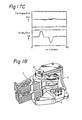
- Fig. 18 of the accompanying drawings shows a perspective view of a swing-type multi-actuator which has two actuators.
- the device comprises two actuators 1, a pivot shaft 2, a magnet housing 3 and a base support 4.
- the two actuators 1 are mechanically coupled with each other through the pivot shaft 2, the magnet housing 3 and the base support 4. Therefore, mechanical vibration of one actuator is induced in the other actuator through the mechanical coupling parts (the pivot shaft, the magnet housing, and the base support), and the transferred vibrations would cause an error in positioning of the other actuator.
- the mechanical vibration has the frequency spectrum between several hundreds Hz and several kHz. Since the cutoff frequency in a servo loop for head positioning is usually several hundreds Hz, which is less than about one seventh of the mechanical resonance frequency of the actuator 1, the servo loop circuit cannot make the actuator follow the transferred mechanical vibration and, therefore, the transferred undesired mechanical vibration directly causes a head positioning error.
- a prior proposal for solving the problem is to decrease the slewing rate (gradient) of the drive current in the actuator 1 so that the current has no spectrum close to the mechanical resonance frequency.
- This decrease in slewing rate has the advantage that the positioning servo loop is held stable, and the circuit is simple.
- the prior art proposal has the disadvantages that the drive current or the power supply voltage must be large, since the waveform of the drive current must be triangular for high-velocity operation, and that the temperature of the head disk assembly is considerably increased due to large power consumption in a voice coil motor (VCM) and in an amplifier which feeds the current to the VCM.
- VCM voice coil motor
- an actuator access control system for positioning an actuator which carries a magnetic head to a desired track during a seek stroke by feeding drive current into a motor of the actuator, characterised in that the drive current comprises a pair of trapezoidal waveform signals of opposite polarities; and in that the waveform factor, which is the ratio of the peak plateau period to the base period of the trapezoidal waveform, is dependent upon the length of the seek stroke, so that the mechanical resonance frequency of the actuator coincides with a frequency in the power spectrum of the trapezoidal waveform at which the power level is low or zero.
- equation (1) the interaction between actuators depends upon the product of mutual compliance and drive power (G12F2, G21,F1). Therefore, even if the mutual compliances G12 and G21 are large, the interaction may be small or zero if the spectra of the drive powers F1 and F2 are small or zero.
- a pair of trapezoidal drive currents for acceleration and deceleration can suppress spectra close to the mechanical resonance frequency of mutual compliances G12 and G21, and at higher frequencies.
- the trapezoidal drive current can provide accurate and stable positioning of a head, and the magnitude of the mutual interaction can be adjusted by controlling the shape of trapezoidal waveform.
- the less the mutual interaction is the more the power consumption in the drive coil of the actuator increases, and the problem of the power consumption must therefore be considered.
- Fig. 1A shows a trapezoidal waveform.
- T ACC is the time of acceleration or deceleration (base of the trapezoidal waveform)
- T CON is the time of constant acceleration or deceleration (the plateau of the trapezoidal waveform)
- T O is the time of constant velocity between acceleration and deceleration (i.e. the drive current is zero)
- Fig. 1B shows the power spectrum of the trapezoidal waveform of Fig. 1A.
- the prior devices cannot have any characteristic frequencies such as f1, f2, f3 ... so that a prior actuator must have a high mechanical resonance frequency.
- the mechanical resonance frequency of an actuator according to the present invention appears in the range where a power spectrum of the drive current exists, and it coincides with a frequency at which the power level is minimum.
- Fig. 2 shows power spectra of the drive current when an actuator 1 moves a predetermined distance in a predetermined time for a value of ( ⁇ ) between 0.0 and 0.5, where ( ⁇ ) is zero.
- the waveform factor (0,0) is the same as a triangular drive current using the prior slewing rate restriction method, and the waveform factor (1,1) is the same as a conventional "bang-bang" control which uses a rectangular waveform.
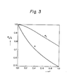
- Fig. 3 shows the dependency of the amplitude A of the drive current and the power consumption P L in the drive coil on the value ( ⁇ ).
- the larger the value ( ⁇ ) the smaller are the amplitude A and the power consumption P L . Therefore, when there is a margin in preventing mechanical interaction, it is preferably to use a trapezoidal waveform which has a value ( ⁇ ) larger than 0.2.
- Fig. 4A shows the distribution of the power spectrum of drive current when a constant velocity period in which no drive current flows is provided between the acceleration period and the deceleration period.
- Fig. 4A shows the curves of the power spectra of drive current based upon Figs 2 and 3 on the condition that the value ( ⁇ ) and the amplitude A do not change, but only the value ( ⁇ ) is changed.
- the envelopes of the power spectra of Fig. 4A are included in the envelope of Fig. 4B, which is the envelope of the power spectra of a positive trapezoidal waveform E in Fig. 4C.
- the waveform E is an isolated (positive) waveform having an amplitude twice as high as that of each of the pair of trapezoidal waveforms.
- the envelope of Fig. 4B depends upon only the value ( ⁇ ) and the acceleration time T ACC , but is independent of the value ( ⁇ ).
- the maximum magnitude of mechanical interaction is defined by the shape of the acceleration current, but is independent of the seek stroke.
- a trapezoidal waveform with a value ( ⁇ ) nearly equal to 0.2 is used so that mechanical interaction is suppressed;
- a trapezoidal waveform with a value ( ⁇ ) larger than 0.2, and a value ( ⁇ ) larger than 0 is used so that the magnitude of mechanical interaction is similar to that in a short-stroke seek, and the waveform factor ( ⁇ , ⁇ ) is determined for each seek length so that the average power consumption in the drive coil is minimized.
- Fig. 5 shows the waveform in each case.
- the acceleration time T ACC is short, and the drive current includes a large amount of high-frequency spectra.
- the power consumption is small and, therefore, the waveform factor ( ⁇ , ⁇ ) which is effective to suppress mechanical interaction does not give rise to a problem of excess heating.
- a middle-stroke seek in Fig. 5B the seek stroke is longer and the acceleration time T ACC of the actuator 1 is longer. Therefore, there is a margin for suppressing mechanical interaction.
- ( ⁇ ) is larger than 0.2, the amplitude A of the drive current may be small as shown in Fig. 4, and the power supply voltage and the power consumption in the drive amplifier are also reduced.
- the presence of the constant velocity region reduces the maximum velocity at the access time, and reduces the shock to the head positioning mechanism in a runaway.
- the effect of the present invention operates also for the transfer functions G11 and G22 of an accessed actuator 1 itself in the equation (1).
- the vibration of the accessed actuator is therefore also suppressed.
- smooth actuator operation is accomplished.
- the present invention is therefore effective not only to suppress interaction, but also to provide stable control of the actuator itself.
- Fig. 6 is a block diagram of an access control circuit according to the present invention.
- the circuit comprises a position transducer 15, a trapezoidal waveform generator 16, a deceleration velocity profile generator 17, a velocity transducer 18, a velocity control circuit 19, a drive signal switching circuit 20, a position following control circuit 21, and a power amplifier 22.
- the trapezoidal waveform generator 16 is shown in Fig. 7, and comprises a micro-processor 31, a D/A (digital to analog) converter 32 and a difference track data latch circuit 33.
- micro-processor 31 The operation of the micro-processor 31 is shown in the flow-chart in Fig. 8, in which an acceleration signal, and a deceleration signal of the same waveform as the acceleration signal and of opposite polarity, are generated according to the seek stroke, so that the actuator 1 is moved to the desired track.
- the power amplifier 22 (Fig. 6) is a current control type amplifier which is not affected by voltage fluctuations in the power supply, nor by change of resistance of a drive coil due to change of temperature, so that the feed-forward velocity control by the trapezoidal signals is stably carried out.
- the seek time which lies between track following periods (I), is divided into a feed-forward velocity control period (II), and a feed-back velocity control period (III) which is about 20-30 percent of the total of the periods (II) and (III).
- the period (III) functions to decelerate the actuator 1 to position it at the desired position and to remove the control error in the period (II).
- the trapezoidal waveform generator 16 (Fig. 6) and the velocity control circuit 19 which generates a drive signal for causing the actuator 1 to follow the deceleration reference velocity profile, operate at the same time.
- the drive signal switching circuit 20 switches the drive signal from the trapezoidal waveform from the circuit 16 to the feed-back control signal from the circuit 19.
- the actuator may be decelerated accurately by keeping the drive signal trapezoidal.
- the generator 17 may be omitted, for simplification of the circuit, since the sensitivity of the interaction suppression control by the trapezoidal signal is low as regards the change of the control parameters. If it is omitted, the position error (distance to target) is taken as the deceleration reference velocity.
- the position following control circuit 21 functions to follow the actuator 1 to the object position, after the actuator 1 reaches the object position by the feed-forward velocity control, and the switch 23 is switched to the contact (b).
- the trapezoidal waveform is divided into time durations T0 to T6, as shown in Fig. 8A, according to the points of change in the amplitude of the signal, and incremental values (or decremental values) ⁇ 1 to ⁇ 6 at respective change points are stored in the memory table of the memory of the microprocessor 31.
- the access command ACC (Fig. 7) states how many tracks the actuator should seek, that command ACC is stored in the latch circuit 33 according to the instruction by the microprocessor 31. Then, the status 101 (seek start ) changes to Y (yes). Then, in a step 102, the number of difference tracks is loaded by the microprocessor 31. In a step 111, the table data, T0 to T6 and ⁇ 0 to ⁇ 6, are loaded into the microprocessor 31. In a step 112, the timer and the output register are set to the n'th time duration (T N ) and the n'th incremental value ( ⁇ N ).
- the feed-forward control output V F is compared with the feed-back control output V B . If the output of the step 121 is N (no), and the content of the timer is not zero (step 122), the steps 113, 121 and 122 are repeated.
- step 122 If the output of the step 122 is Y (yes) because the timer becomes zero, the steps 112, 113, 121 and 122 are repeated so that the process for the next time slot T i+1 is carried out.
- step 131 sends the switch control signal so that the switch 19 is switched to the contact (b) (feed-back control). Then the control returns to the step 101.
- the microprocessor can generate any desired trapezoidal waveform, so that the optimum trapezoidal waveform depending upon the mechanical resonance frequency is obtained.
- the present invention is also applicable to a digital positioning control, in which accurate detection of location is possible.
- the invention uses a feed-forward control which is implemented by addition/subtraction for the major portion of the control, and a feed-back control when the speed of the actuator 1 reaches about one fifth of the maximum velocity. Therefore, the necessary signal processing speed for the access control circuit is considerably reduced.
- time-division multiplex control of the actuators is possible by use of the invention.
- Fig. 10 is a block diagram of a second embodiment of a control circuit according to the invention.
- the circuit includes a half distance subtractor 41, a maximum velocity signal generator 42 and an analog adder 43.
- the maximum velocity signal generator 42 is implemented by a memory which provides the maximum reference velocity of the actuator according to the seek stroke.
- the subtractor 41 provides the remaining seek stroke until the 1 ⁇ 2 seek stroke position.
- the embodiment of Fig. 10 uses the symmetrical nature of the trapezoidal waveform.
- a feedback control is used in both the acceleration step and the deceleration step of an actuator 1.
- the half distance subtractor 41 provides the remaining stroke up to the starting point of the constant velocity control.
- the embodiment of Fig. 10 has the feature that the control error of the actuator is compensated during the acceleration step, so that the influence of an external disturbance is reduced.
- Fig. 12 is a block diagram of a third embodiment of access control circuit according to the invention.
- the circuit includes a primary reference velocity profile generator 51, a secondary reference velocity profile generator 52, an offset velocity signal generator 53 and a parameter control circuit 54.
- the embodiment of Fig. 12 has the pair of reference velocity profile generators 51 and 52 which are not provided in the embodiment of Fig. 10. Those generators 51 and 52 generate the exponential function signals as shown in the reference velocity profile of Fig. 13.
- the remaining distance X′ to the 1/2 seek stroke position is replaced by the remaining distance X to the object track, and the velocity reference signal is generated in the sequence of control periods VId, Vd and IVd, in opposite steps to the acceleration period.
- the switching of the velocity reference generator, or the control period, is accomplished by the switching circuit 20, when the outputs of all of the velocity reference generators coincide with each other.
- control parameters for the above operations are provided by the parameter control circuit 54, which may be similar to that of Fig. 7.
- Fig. 12 has the feature that the circuit structure is similar to that of a conventional access control circuit, and that the trapezoidal waveform control is accomplished with stable operation, without being affected by external disturbances.
- Fig. 14 shows a fourth embodiment.
- the circuit of Fig. 14 generates a velocity reference signal which causes trapezoidal drive current to flow in the VCM.
- the circuit includes a ROM pointer 55, a track counter 56, a velocity profile generator 57, a D/A converter 58, a half seek stroke detector 59, an up/down selector 60, a time counter 61, a count limiter 62 and a smoother 63.
- Fig. 15 shows the operation and waveforms of the circuit of Fig. 14.
- the velocity profile generator 57 stores the velocity reference signal according to the seek stroke, and the storage location of each velocity reference signal is indicated by the ROM pointer 55.
- a track crossing pulse which is provided when a head crosses a track boundary, increments the track counter 56, and the velocity profile generator 57 provides the velocity reference signal in sequence.
- the count limiter 62 operates also.
- the count limiter 62 functions to detect that the velocity reference signal reaches the maximum value (V max ).
- V max maximum value
- the deceleration operation begins.
- the velocity reference signal is generated in the opposite manner to that of the acceleration period, and the time counter 61 is decremented until it reaches zero.
- the track counter 56 becomes active.
- the track counter 56 is selected to be in the count-down mode by the 1 ⁇ 2 seek stroke detector 59 and the up/down selector 60.
- the velocity reference signal is generated by decrementing the track counter 56.
- the smoother 63 integrates the drive current functions to smooth the stepwise velocity reference signal.
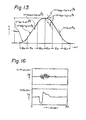
- Figs. 16 and 17 show the seek operation characteristics of the two swing-type actuators. Those show the waveform I D of the drive current, and the head positioning error ⁇ D produced by mechanical vibration interaction when another actuator is driven.
- Fig. 16 shows the conventional case in which track seeking with the maximum interaction is executed.
- Fig. 17A shows the short seek stroke operation of the present invention
- Fig. 17B shows the middle seek stroke operation of the invention
- Fig. 17C shows the long seek stroke operation of the invention.
- the head positioning error produced by the interaction is suppressed by more than 15 dB. Furthermore, the present invention provides faster and more accurate position control of the actuators.
- the waveform factor ( ⁇ ) might be between 0.1 and 0.4.
- an actuator is controlled in the seek operation by a trapezoidal waveform current, and the mechanical interaction is suppressed considerably. Furthermore, since the mechanical resonance of the actuator itself is suppressed, high-speed positioning of the actuator is also achieved. Also, by using the present invention, the track density of a magnetic disk storage can be considerably increased.
- the present invention is applicable not only to a multi-actuator system, but also a single actuator system.
Landscapes
- Moving Of Head For Track Selection And Changing (AREA)
- Moving Of The Head To Find And Align With The Track (AREA)
- Control Of Position Or Direction (AREA)
- Control Of Linear Motors (AREA)
Applications Claiming Priority (2)
| Application Number | Priority Date | Filing Date | Title |
|---|---|---|---|
| JP263699/85 | 1985-11-26 | ||
| JP60263699A JPH0833771B2 (ja) | 1985-11-26 | 1985-11-26 | アクチユエ−タのアクセス制御方法 |
Publications (3)
| Publication Number | Publication Date |
|---|---|
| EP0226355A2 true EP0226355A2 (fr) | 1987-06-24 |
| EP0226355A3 EP0226355A3 (en) | 1988-09-07 |
| EP0226355B1 EP0226355B1 (fr) | 1991-05-15 |
Family
ID=17393105
Family Applications (1)
| Application Number | Title | Priority Date | Filing Date |
|---|---|---|---|
| EP86309186A Expired - Lifetime EP0226355B1 (fr) | 1985-11-26 | 1986-11-25 | Système de commande d'actionneur |
Country Status (4)
| Country | Link |
|---|---|
| US (1) | US4796112A (fr) |
| EP (1) | EP0226355B1 (fr) |
| JP (1) | JPH0833771B2 (fr) |
| DE (1) | DE3679295D1 (fr) |
Cited By (5)
| Publication number | Priority date | Publication date | Assignee | Title |
|---|---|---|---|---|
| EP0361381A3 (fr) * | 1988-09-27 | 1990-09-05 | Nec Corporation | Système de commande de vitesse d'un actionneur pour déplacer une tête magnétique dans une unité de disques et unité de disques avec un tel système |
| EP0361786A3 (en) * | 1988-09-26 | 1990-09-05 | International Business Machines Corporation | Disk file digita servo control |
| WO1990013113A1 (fr) * | 1989-04-27 | 1990-11-01 | Siemens Aktiengesellschaft | Procede et dispositif de positionnement d'une memoire a disque magnetique |
| GB2238888A (en) * | 1989-11-15 | 1991-06-12 | Okuma Machinery Works Ltd | Index control apparatus for tool rest of an NC lathe |
| WO1991010991A1 (fr) * | 1990-01-11 | 1991-07-25 | Siemens Nixdorf Informationssysteme Aktiengesellschaft | Procede et circuit servant au reglage du bras d'acces d'un systeme de memoire a disques |
Families Citing this family (18)
| Publication number | Priority date | Publication date | Assignee | Title |
|---|---|---|---|---|
| JPH01173209A (ja) * | 1987-12-28 | 1989-07-07 | Nitto Seiko Co Ltd | 産業用ロボットの制御方法 |
| JP2768696B2 (ja) * | 1988-08-31 | 1998-06-25 | 東芝メカトロニクス株式会社 | サーボモータの制御装置 |
| JPH03164813A (ja) * | 1989-11-22 | 1991-07-16 | Honda Motor Co Ltd | ロボット等の加減速制御方法 |
| US5132855A (en) * | 1989-11-28 | 1992-07-21 | Seagate Technology, Inc. | Adaptive velocity profile selection based on torque constant measurement |
| JP2861277B2 (ja) * | 1990-06-04 | 1999-02-24 | 三菱電機株式会社 | 位置決め制御装置および位置決め制御方法 |
| JP2550446B2 (ja) * | 1991-04-30 | 1996-11-06 | 富士通株式会社 | 磁気ディスク装置のヘッド位置決め方式 |
| US5307212A (en) * | 1991-08-22 | 1994-04-26 | Rohm Co., Ltd. | Trapezoidal wave generation in a video control signal write circuit |
| JP2680260B2 (ja) * | 1994-02-14 | 1997-11-19 | インターナショナル・ビジネス・マシーンズ・コーポレイション | ディスク記憶装置及びヘッド制御装置 |
| EP1152409B1 (fr) * | 1994-06-07 | 2006-08-09 | Hitachi Global Storage Technologies Japan, Ltd. | Appareil d'emmagasinage d'informations |
| US7433144B2 (en) * | 1999-03-04 | 2008-10-07 | Convolve, Inc. | Dynamic system control method |
| JP2001086798A (ja) * | 1999-09-16 | 2001-03-30 | Fuji Photo Optical Co Ltd | モータの制御方法及び装置 |
| US6597529B1 (en) * | 1999-11-12 | 2003-07-22 | Maxtor Corporation | Method and apparatus for reducing acoustic noise in servo-controlled system |
| US6519109B1 (en) * | 2000-07-21 | 2003-02-11 | International Business Machines Corporation | Method and apparatus for providing feedforward control of two interacting actuators |
| US6865064B2 (en) * | 2001-08-29 | 2005-03-08 | Olympus Corporation | Drive apparatus and drive method for electromagnetic drive actuator |
| JP3814509B2 (ja) * | 2001-10-01 | 2006-08-30 | キヤノン株式会社 | モータの制御のための方法及び装置 |
| US7082010B1 (en) | 2001-11-09 | 2006-07-25 | Maxtor Corporation | Method and apparatus for reducing seek acoustics in a disk drive using feedback during large current transitions |
| US6870342B2 (en) * | 2002-10-03 | 2005-03-22 | Seagate Technology Llc | Cosine bang-bang seek control for a voice coil of a disc drive |
| FR2857070B1 (fr) * | 2003-07-02 | 2005-09-30 | Giat Ind Sa | Dispositif d'amortissement actif d'une arme par accord de la transmission |
Family Cites Families (5)
| Publication number | Priority date | Publication date | Assignee | Title |
|---|---|---|---|---|
| US3828236A (en) * | 1971-06-07 | 1974-08-06 | Transportation Technology | Linear motor acceleration control system |
| JPS5246356B2 (fr) * | 1972-08-12 | 1977-11-24 | ||
| US3798427A (en) * | 1973-02-27 | 1974-03-19 | Giddings & Lewis | Automatic deceleration to zero velocity in iteratively computing numerical control systems |
| US4342378A (en) * | 1979-12-27 | 1982-08-03 | Otis Elevator Company | Elevator door motion bench velocity |
| EP0103493B1 (fr) * | 1982-09-15 | 1987-12-16 | Ampex Corporation | Générateur de commande de la vitesse réglé à deux échelons |
-
1985
- 1985-11-26 JP JP60263699A patent/JPH0833771B2/ja not_active Expired - Fee Related
-
1986
- 1986-11-24 US US06/934,059 patent/US4796112A/en not_active Expired - Lifetime
- 1986-11-25 DE DE8686309186T patent/DE3679295D1/de not_active Expired - Lifetime
- 1986-11-25 EP EP86309186A patent/EP0226355B1/fr not_active Expired - Lifetime
Cited By (7)
| Publication number | Priority date | Publication date | Assignee | Title |
|---|---|---|---|---|
| EP0361786A3 (en) * | 1988-09-26 | 1990-09-05 | International Business Machines Corporation | Disk file digita servo control |
| EP0361381A3 (fr) * | 1988-09-27 | 1990-09-05 | Nec Corporation | Système de commande de vitesse d'un actionneur pour déplacer une tête magnétique dans une unité de disques et unité de disques avec un tel système |
| WO1990013113A1 (fr) * | 1989-04-27 | 1990-11-01 | Siemens Aktiengesellschaft | Procede et dispositif de positionnement d'une memoire a disque magnetique |
| GB2238888A (en) * | 1989-11-15 | 1991-06-12 | Okuma Machinery Works Ltd | Index control apparatus for tool rest of an NC lathe |
| US5121039A (en) * | 1989-11-15 | 1992-06-09 | Okuma Machinery Works | Index control apparatus for tool rest of nc lathe |
| GB2238888B (en) * | 1989-11-15 | 1994-05-04 | Okuma Machinery Works Ltd | Index control apparatus for tool rest of an NC lathe |
| WO1991010991A1 (fr) * | 1990-01-11 | 1991-07-25 | Siemens Nixdorf Informationssysteme Aktiengesellschaft | Procede et circuit servant au reglage du bras d'acces d'un systeme de memoire a disques |
Also Published As
| Publication number | Publication date |
|---|---|
| JPH0833771B2 (ja) | 1996-03-29 |
| US4796112A (en) | 1989-01-03 |
| JPS62125411A (ja) | 1987-06-06 |
| DE3679295D1 (de) | 1991-06-20 |
| EP0226355B1 (fr) | 1991-05-15 |
| EP0226355A3 (en) | 1988-09-07 |
Similar Documents
| Publication | Publication Date | Title |
|---|---|---|
| EP0226355B1 (fr) | Système de commande d'actionneur | |
| EP0000261B1 (fr) | Agencement pour la commande directe et par contre-réaction d'un dispositif de positionnement | |
| KR100413767B1 (ko) | 사인 시크 서보 하드 디스크 드라이브에서의 시크 궤적최적화 방법 및 장치 | |
| EP0064391B1 (fr) | Méthode et appareil de commande d'un moteur pas à pas | |
| US5986426A (en) | Adaptive pulse width modulated motor control | |
| CA1219070A (fr) | Dispositif et methode de positionnement a asservissement | |
| JP3377013B2 (ja) | ディスク装置のシーク制御装置及びそれを用いたシーク制御方法 | |
| EP0003070A1 (fr) | Dispositif digital de positionnement utilisant un modèle du système physique pour un système de commande à temps optimal | |
| EP0049948B1 (fr) | Système de contrôle d'un moteur pour le positionnement d'un transducteur | |
| WO1993009480A1 (fr) | Procede et dispositif de recherche de bruits acoustiques faibles | |
| US5781362A (en) | Servo control system for driving a voice coil motor with pulse width and gain control | |
| US7636605B2 (en) | Magnetic disk device and head-position control method | |
| US3436629A (en) | Balanced vertical positioning system | |
| KR100291221B1 (ko) | 방방제어기를 이용한 위치제어장치 | |
| Takaishi et al. | Seek control and settling control taming actuator resonance of hard disk drives | |
| JPH01162279A (ja) | 磁気デイスク装置の制御回路 | |
| A. áFennema | State-space intercept method for seek control of optical disk drives | |
| JP2812073B2 (ja) | ディスク装置のトラック間アクセス方式 | |
| JP3369509B2 (ja) | 2自由度制御系の制御方法及び装置、磁気ディスク装置及びその制御方法 | |
| JPH05501935A (ja) | ディスクメモリ装置のアクセスアームの調整方法および回路装置 | |
| Kobayashi et al. | Adaptive seeking control for magnetic disk drives | |
| JPS58201113A (ja) | 可動体位置決めサ−ボシステム | |
| Yen et al. | A trajectory feedback control for the computer disk file track-accessing/following servo | |
| Yen et al. | T12c= t12c1+ t12c3+ t12c5+ t12c7+ 111 (12d) | |
| JPS6238572A (ja) | 記録情報再生ヘツドの位置決め制御装置 |
Legal Events
| Date | Code | Title | Description |
|---|---|---|---|
| PUAI | Public reference made under article 153(3) epc to a published international application that has entered the european phase |
Free format text: ORIGINAL CODE: 0009012 |
|
| 17P | Request for examination filed |
Effective date: 19861210 |
|
| AK | Designated contracting states |
Kind code of ref document: A2 Designated state(s): DE FR GB |
|
| PUAL | Search report despatched |
Free format text: ORIGINAL CODE: 0009013 |
|
| AK | Designated contracting states |
Kind code of ref document: A3 Designated state(s): DE FR GB |
|
| 17Q | First examination report despatched |
Effective date: 19900119 |
|
| RAP1 | Party data changed (applicant data changed or rights of an application transferred) |
Owner name: NIPPON TELEGRAPH AND TELEPHONE CORPORATION |
|
| GRAA | (expected) grant |
Free format text: ORIGINAL CODE: 0009210 |
|
| AK | Designated contracting states |
Kind code of ref document: B1 Designated state(s): DE FR GB |
|
| REF | Corresponds to: |
Ref document number: 3679295 Country of ref document: DE Date of ref document: 19910620 |
|
| ET | Fr: translation filed | ||
| PLBE | No opposition filed within time limit |
Free format text: ORIGINAL CODE: 0009261 |
|
| STAA | Information on the status of an ep patent application or granted ep patent |
Free format text: STATUS: NO OPPOSITION FILED WITHIN TIME LIMIT |
|
| 26N | No opposition filed | ||
| REG | Reference to a national code |
Ref country code: GB Ref legal event code: IF02 |
|
| PGFP | Annual fee paid to national office [announced via postgrant information from national office to epo] |
Ref country code: DE Payment date: 20051116 Year of fee payment: 20 |
|
| PGFP | Annual fee paid to national office [announced via postgrant information from national office to epo] |
Ref country code: GB Payment date: 20051123 Year of fee payment: 20 |
|
| PGFP | Annual fee paid to national office [announced via postgrant information from national office to epo] |
Ref country code: FR Payment date: 20051128 Year of fee payment: 20 |
|
| REG | Reference to a national code |
Ref country code: GB Ref legal event code: PE20 |
|
| PG25 | Lapsed in a contracting state [announced via postgrant information from national office to epo] |
Ref country code: GB Free format text: LAPSE BECAUSE OF EXPIRATION OF PROTECTION Effective date: 20061124 |