EP0226477B1 - Gewindebolzenschneider - Google Patents
Gewindebolzenschneider Download PDFInfo
- Publication number
- EP0226477B1 EP0226477B1 EP86402191A EP86402191A EP0226477B1 EP 0226477 B1 EP0226477 B1 EP 0226477B1 EP 86402191 A EP86402191 A EP 86402191A EP 86402191 A EP86402191 A EP 86402191A EP 0226477 B1 EP0226477 B1 EP 0226477B1
- Authority
- EP
- European Patent Office
- Prior art keywords
- threaded
- cutting
- fixed
- nests
- rod
- Prior art date
- Legal status (The legal status is an assumption and is not a legal conclusion. Google has not performed a legal analysis and makes no representation as to the accuracy of the status listed.)
- Expired - Lifetime
Links
Images

Classifications
-
- B—PERFORMING OPERATIONS; TRANSPORTING
- B23—MACHINE TOOLS; METAL-WORKING NOT OTHERWISE PROVIDED FOR
- B23D—PLANING; SLOTTING; SHEARING; BROACHING; SAWING; FILING; SCRAPING; LIKE OPERATIONS FOR WORKING METAL BY REMOVING MATERIAL, NOT OTHERWISE PROVIDED FOR
- B23D17/00—Shearing machines or shearing devices cutting by blades pivoted on a single axis
- B23D17/02—Shearing machines or shearing devices cutting by blades pivoted on a single axis characterised by drives or gearings therefor
- B23D17/08—Shearing machines or shearing devices cutting by blades pivoted on a single axis characterised by drives or gearings therefor actuated by hand or foot operated lever mechanism
-
- B—PERFORMING OPERATIONS; TRANSPORTING
- B23—MACHINE TOOLS; METAL-WORKING NOT OTHERWISE PROVIDED FOR
- B23D—PLANING; SLOTTING; SHEARING; BROACHING; SAWING; FILING; SCRAPING; LIKE OPERATIONS FOR WORKING METAL BY REMOVING MATERIAL, NOT OTHERWISE PROVIDED FOR
- B23D23/00—Machines or devices for shearing or cutting profiled stock
-
- Y—GENERAL TAGGING OF NEW TECHNOLOGICAL DEVELOPMENTS; GENERAL TAGGING OF CROSS-SECTIONAL TECHNOLOGIES SPANNING OVER SEVERAL SECTIONS OF THE IPC; TECHNICAL SUBJECTS COVERED BY FORMER USPC CROSS-REFERENCE ART COLLECTIONS [XRACs] AND DIGESTS
- Y10—TECHNICAL SUBJECTS COVERED BY FORMER USPC
- Y10S—TECHNICAL SUBJECTS COVERED BY FORMER USPC CROSS-REFERENCE ART COLLECTIONS [XRACs] AND DIGESTS
- Y10S83/00—Cutting
- Y10S83/929—Particular nature of work or product
- Y10S83/953—Particular nature of work or product with work support
-
- Y—GENERAL TAGGING OF NEW TECHNOLOGICAL DEVELOPMENTS; GENERAL TAGGING OF CROSS-SECTIONAL TECHNOLOGIES SPANNING OVER SEVERAL SECTIONS OF THE IPC; TECHNICAL SUBJECTS COVERED BY FORMER USPC CROSS-REFERENCE ART COLLECTIONS [XRACs] AND DIGESTS
- Y10—TECHNICAL SUBJECTS COVERED BY FORMER USPC
- Y10T—TECHNICAL SUBJECTS COVERED BY FORMER US CLASSIFICATION
- Y10T83/00—Cutting
- Y10T83/869—Means to drive or to guide tool
- Y10T83/8798—With simple oscillating motion only
- Y10T83/8804—Tool driver movable relative to tool support
- Y10T83/8809—Fixed axis lever
-
- Y—GENERAL TAGGING OF NEW TECHNOLOGICAL DEVELOPMENTS; GENERAL TAGGING OF CROSS-SECTIONAL TECHNOLOGIES SPANNING OVER SEVERAL SECTIONS OF THE IPC; TECHNICAL SUBJECTS COVERED BY FORMER USPC CROSS-REFERENCE ART COLLECTIONS [XRACs] AND DIGESTS
- Y10—TECHNICAL SUBJECTS COVERED BY FORMER USPC
- Y10T—TECHNICAL SUBJECTS COVERED BY FORMER US CLASSIFICATION
- Y10T83/00—Cutting
- Y10T83/929—Tool or tool with support
- Y10T83/9411—Cutting couple type
- Y10T83/9447—Shear type
-
- Y—GENERAL TAGGING OF NEW TECHNOLOGICAL DEVELOPMENTS; GENERAL TAGGING OF CROSS-SECTIONAL TECHNOLOGIES SPANNING OVER SEVERAL SECTIONS OF THE IPC; TECHNICAL SUBJECTS COVERED BY FORMER USPC CROSS-REFERENCE ART COLLECTIONS [XRACs] AND DIGESTS
- Y10—TECHNICAL SUBJECTS COVERED BY FORMER USPC
- Y10T—TECHNICAL SUBJECTS COVERED BY FORMER US CLASSIFICATION
- Y10T83/00—Cutting
- Y10T83/97—Miscellaneous
Definitions
- the invention relates according to the preamble of claim 1, an apparatus for cutting threaded rods, comprising a frame and a force multiplier lever.
- This device therefore requires that the threaded rod be screwed beforehand over the entire length of the section to be obtained, before sectioning the rod, which causes a loss of time and considerable discomfort, without however eliminating the risks of deformation of the thread in the sectioning plane, which, as with the device mentioned above, causes difficulties in positioning the nuts on the rod and makes it necessary to use a key.
- the present invention aims to remedy these drawbacks.
- the invention as characterized in the claims, solves the problem of cutting a threaded rod, whatever its length, by direct transverse positioning of the cutting device, without deformation of the thread in the cutting plane .
- the apparatus for cutting threaded rods is mainly characterized in that the apparatus comprises a frame and a force multiplier lever, the fixed part is removable and its fixed and mobile parts are provided with half threaded impressions - cylinders of the same dimension but arranged in opposite directions.
- the half-cylindrical threaded impressions formed in the fixed and movable parts are made according to the same thread corresponding to that of the rod to be cut.
- the fixed part is made removable by means of a bracket fixed, by bolt, on the frame of the device.
- the semi-cylindrical threaded impressions each correspond to a different diameter of threaded rod and are arranged in ascending order of the diameters towards the axis of articulation of the movable part.
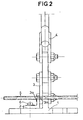
- the figures show an apparatus for cutting threaded rods comprising a frame, comprising a removable fixed part 2, fixed by a bolt 6, provided, at its upper part, with a semi-cylindrical threaded imprint 2a, and with respect to which s articulates a movable part 3, provided, at its lower part, with another semi-cylindrical threaded imprint 3a, arranged in the opposite direction to that 2a arranged in the fixed part 2.
- the mobile part 3, sliding against the fixed part 2 is actuated by a force multiplying lever 4.
- the half-cylindrical threaded impressions 2a and 3a, arranged in the fixed 2 and movable 3 parts, are produced according to the same thread corresponding to that of the rods to be cut.
- the threaded imprints 2a and 3a come to bear against the threaded rods 5, matching the shape of the thread.
- the threaded rod 5 is placed on the impression 2a by making coincide, with the thumbnail, the sectioning plane chosen with the internal edge of the threaded impression 2a, then the lever 4 is actuated to obtain the articulation of the movable part 3 and the bearing of the threaded imprint 3a which it comprises against the threaded rod 5. It is then enough to accentuate the effort exerted on the lever 4, to obtain the clean and precise sectioning of the threaded rod 5.
- the sections of rods obtained can be very easily released, since they are completely released from the sectioning.
- the fixed 2 and movable 3 parts can include several juxtaposed imprints corresponding to different diameters of threaded rods. It is simply enough, for a matter of cutting force, to have the threaded impressions in increasing order of diameters towards the axis of articulation of the movable part 3.
Landscapes
- Engineering & Computer Science (AREA)
- Mechanical Engineering (AREA)
- Shearing Machines (AREA)
- Dowels (AREA)
- Prostheses (AREA)
- Re-Forming, After-Treatment, Cutting And Transporting Of Glass Products (AREA)
- Investigation Of Foundation Soil And Reinforcement Of Foundation Soil By Compacting Or Drainage (AREA)
- Fluid-Damping Devices (AREA)
- Processing Of Stones Or Stones Resemblance Materials (AREA)
- Organic Low-Molecular-Weight Compounds And Preparation Thereof (AREA)
- Harvester Elements (AREA)
Claims (5)
Priority Applications (1)
| Application Number | Priority Date | Filing Date | Title |
|---|---|---|---|
| AT86402191T ATE54081T1 (de) | 1985-10-07 | 1986-10-03 | Gewindebolzenschneider. |
Applications Claiming Priority (2)
| Application Number | Priority Date | Filing Date | Title |
|---|---|---|---|
| FR8514908A FR2588205B1 (fr) | 1985-10-07 | 1985-10-07 | Appareil de coupe de tiges filetees |
| FR8514908 | 1985-10-07 |
Publications (2)
| Publication Number | Publication Date |
|---|---|
| EP0226477A1 EP0226477A1 (de) | 1987-06-24 |
| EP0226477B1 true EP0226477B1 (de) | 1990-06-27 |
Family
ID=9323643
Family Applications (1)
| Application Number | Title | Priority Date | Filing Date |
|---|---|---|---|
| EP86402191A Expired - Lifetime EP0226477B1 (de) | 1985-10-07 | 1986-10-03 | Gewindebolzenschneider |
Country Status (6)
| Country | Link |
|---|---|
| US (1) | US4722257A (de) |
| EP (1) | EP0226477B1 (de) |
| AT (1) | ATE54081T1 (de) |
| DE (1) | DE3672216D1 (de) |
| ES (1) | ES2016802B3 (de) |
| FR (1) | FR2588205B1 (de) |
Cited By (1)
| Publication number | Priority date | Publication date | Assignee | Title |
|---|---|---|---|---|
| RU2213648C1 (ru) * | 2002-04-05 | 2003-10-10 | Кульбацкий Евгений Борисович | Ручные ножницы |
Families Citing this family (9)
| Publication number | Priority date | Publication date | Assignee | Title |
|---|---|---|---|---|
| US5261303A (en) * | 1992-03-23 | 1993-11-16 | Strippgen Walter E | Rod cutter |
| GB2275221B (en) * | 1993-02-18 | 1995-11-22 | Ogura Kk | Anti-breakage thread configuration in apparatus for cutting threaded rods |
| JP2603806Y2 (ja) * | 1993-03-01 | 2000-03-27 | 株式会社オグラ | ねじ棒切断装置 |
| USD363865S (en) | 1994-04-25 | 1995-11-07 | Cristobal Pulido | Rebar cutting tool |
| US5840004A (en) * | 1994-07-22 | 1998-11-24 | Ranpak Corp. | Cushioning conversion machine and method |
| BR0006470A (pt) * | 2000-12-04 | 2002-07-09 | Alberto Mesquita Grandi | Sistema multi-axial de alavancas |
| JP3089659U (ja) * | 2002-04-30 | 2002-10-31 | 株式会社小林工具製作所 | 鉄筋カッター |
| US20080000091A1 (en) * | 2006-06-29 | 2008-01-03 | Toho Koki Co., Ltd. | Threaded Rod Cutter |
| EP2077932B1 (de) | 2006-10-20 | 2014-01-22 | Etablissements Pierre Grehal et Cie SA | Schneidwerkzeug zum segmentieren von festen langen elementen |
Family Cites Families (9)
| Publication number | Priority date | Publication date | Assignee | Title |
|---|---|---|---|---|
| US959035A (en) * | 1909-09-02 | 1910-05-24 | Harry Taylor | Metal-shear. |
| US1137093A (en) * | 1914-04-07 | 1915-04-27 | Niels C Simonsen | Rod-cutter. |
| US1623689A (en) * | 1924-05-12 | 1927-04-05 | Sebert A Lind | Tool |
| US2850926A (en) * | 1953-11-09 | 1958-09-09 | Tronic Tooling Corp | Vise |
| NL230530A (de) * | 1957-08-15 | |||
| US3089241A (en) * | 1960-11-21 | 1963-05-14 | Vaco Products Co | Cutoff device for threaded bolts and screws |
| FR1463766A (fr) * | 1962-12-13 | 1966-07-22 | Vaco Products Co | Dispositif pour tronçonner des boulons ou vis à filets |
| US3495331A (en) * | 1967-09-20 | 1970-02-17 | Edwin Graham Riggs | Threaded-rod cutter |
| US3757621A (en) * | 1970-02-20 | 1973-09-11 | Intermenua Pty Ltd | Guillotines and like shearing machines |
-
1985
- 1985-10-07 FR FR8514908A patent/FR2588205B1/fr not_active Expired
-
1986
- 1986-10-03 DE DE8686402191T patent/DE3672216D1/de not_active Expired - Fee Related
- 1986-10-03 ES ES86402191T patent/ES2016802B3/es not_active Expired - Lifetime
- 1986-10-03 EP EP86402191A patent/EP0226477B1/de not_active Expired - Lifetime
- 1986-10-03 AT AT86402191T patent/ATE54081T1/de not_active IP Right Cessation
- 1986-10-06 US US06/915,515 patent/US4722257A/en not_active Expired - Fee Related
Cited By (1)
| Publication number | Priority date | Publication date | Assignee | Title |
|---|---|---|---|---|
| RU2213648C1 (ru) * | 2002-04-05 | 2003-10-10 | Кульбацкий Евгений Борисович | Ручные ножницы |
Also Published As
| Publication number | Publication date |
|---|---|
| US4722257A (en) | 1988-02-02 |
| FR2588205A1 (fr) | 1987-04-10 |
| EP0226477A1 (de) | 1987-06-24 |
| DE3672216D1 (de) | 1990-08-02 |
| ATE54081T1 (de) | 1990-07-15 |
| FR2588205B1 (fr) | 1989-08-18 |
| ES2016802B3 (es) | 1990-12-01 |
Similar Documents
| Publication | Publication Date | Title |
|---|---|---|
| EP0226477A1 (de) | Gewindebolzenschneider | |
| WO2013030334A1 (fr) | Système mécanique comprenant un dispositif de liaison entre une pièce d'usure et son support, godet d'engin de travaux publics et procédé de mise en oeuvre d'un tel système | |
| EP0161168B1 (de) | Kurbelstangenvorrichtung der Art eines kreuzförmig gelenkten Vierecks, insbesondere für Scheibenwischer | |
| FR2722881A1 (fr) | Dispositif de prehension pour la realisation d'essais de traction a haute temperature sur des eprouvettes plates en materiau fragile | |
| EP0284494B1 (de) | Verbindungsvorrichtung für Bauholzteile | |
| EP2077932B1 (de) | Schneidwerkzeug zum segmentieren von festen langen elementen | |
| EP0409708A1 (de) | Plattenkokille für Metallstranggiessen | |
| CA1097051A (fr) | Dispositif de coupe, en particulier coupe-boulon | |
| EP0620057B1 (de) | Zweiteilige Matrize zum Ausrüsten einer Einzieh- und/oder Crimppresse. | |
| FR2687343A1 (fr) | Dispositif de desserrage ou de serrage d'un ecrou visse sur un organe filete. | |
| CA1127562A (fr) | Dispositif de repartition d'un melange de vapeur et de liquide dans un separateur d'axe horizontal | |
| FR2581721A1 (fr) | Bielle en plusieurs parties pour un gros moteur diesel | |
| EP1034580B1 (de) | Erdungsstange mit klemmanschluss und verfahren zur herstellung der klemme | |
| FR2930304A1 (fr) | Procede et dispositif de fixation d'un equipement sur un revetement compressible recouvrant une structure de support | |
| FR2654471A1 (fr) | Dispositif de fixation sur un poteau. | |
| WO1995033930A1 (fr) | Dispositif d'assemblage en ligne de deux elements structuraux tubulaires | |
| FR2594726A1 (fr) | Cintreuse a vis | |
| FR2848278A1 (fr) | Dispositif pour fabriquer des joints | |
| FR2597384A1 (fr) | Disposition de montage et d'articulation multipliant la poussee pour coupe boulons, coupe cables, secateur a 2 mains et pneumatique, pince coupante a main. | |
| FR2595291A1 (fr) | Dispositif hydraulique de bridage pour la fixation demontable des outils de conformation sur les presses a mouler | |
| FR3032729A1 (fr) | Pince pour vibrateur a mors transversaux et vibrateur dote d'une telle pince | |
| FR2689801A1 (fr) | Clé d'outillage universelle réglable pour tête à forme carrée et/ou hexagonale de boulons vis ou écrous. | |
| FR2490996A1 (fr) | Presse a emboutir, notamment a emboutir de plaques indicatrices telles que des plaques publicitaires | |
| EP0214054A1 (de) | Kümpelverfahren zum Herstellen steifer Metallteile zur Bildung von Wärmeschutzbekleidungen von Rohren, Ummantelungen und dergleichen | |
| FR2654026A1 (fr) | Cisaille a main pour la decoupe de fers plats, et notamment de caillebotis. |
Legal Events
| Date | Code | Title | Description |
|---|---|---|---|
| PUAI | Public reference made under article 153(3) epc to a published international application that has entered the european phase |
Free format text: ORIGINAL CODE: 0009012 |
|
| AK | Designated contracting states |
Kind code of ref document: A1 Designated state(s): AT BE CH DE ES FR GB GR IT LI LU NL SE |
|
| 17P | Request for examination filed |
Effective date: 19870706 |
|
| RAP1 | Party data changed (applicant data changed or rights of an application transferred) |
Owner name: APPLICATIONS INDUSTRIELLES DE CHAMPAGNE |
|
| RIN1 | Information on inventor provided before grant (corrected) |
Inventor name: DEON, JEAN-PIERRE Inventor name: GERARD, MICHEL |
|
| 17Q | First examination report despatched |
Effective date: 19890202 |
|
| GRAA | (expected) grant |
Free format text: ORIGINAL CODE: 0009210 |
|
| AK | Designated contracting states |
Kind code of ref document: B1 Designated state(s): AT BE CH DE ES FR GB GR IT LI LU NL SE |
|
| PG25 | Lapsed in a contracting state [announced via postgrant information from national office to epo] |
Ref country code: SE Effective date: 19900627 Ref country code: NL Effective date: 19900627 Ref country code: GR Free format text: LAPSE BECAUSE OF FAILURE TO SUBMIT A TRANSLATION OF THE DESCRIPTION OR TO PAY THE FEE WITHIN THE PRESCRIBED TIME-LIMIT Effective date: 19900627 Ref country code: AT Effective date: 19900627 |
|
| REF | Corresponds to: |
Ref document number: 54081 Country of ref document: AT Date of ref document: 19900715 Kind code of ref document: T |
|
| ITF | It: translation for a ep patent filed | ||
| REF | Corresponds to: |
Ref document number: 3672216 Country of ref document: DE Date of ref document: 19900802 |
|
| PGFP | Annual fee paid to national office [announced via postgrant information from national office to epo] |
Ref country code: GB Payment date: 19900921 Year of fee payment: 5 |
|
| PGFP | Annual fee paid to national office [announced via postgrant information from national office to epo] |
Ref country code: ES Payment date: 19901016 Year of fee payment: 5 |
|
| GBT | Gb: translation of ep patent filed (gb section 77(6)(a)/1977) | ||
| ITTA | It: last paid annual fee | ||
| PG25 | Lapsed in a contracting state [announced via postgrant information from national office to epo] |
Ref country code: LU Free format text: LAPSE BECAUSE OF NON-PAYMENT OF DUE FEES Effective date: 19901031 |
|
| PGFP | Annual fee paid to national office [announced via postgrant information from national office to epo] |
Ref country code: BE Payment date: 19901120 Year of fee payment: 5 |
|
| NLV1 | Nl: lapsed or annulled due to failure to fulfill the requirements of art. 29p and 29m of the patents act | ||
| PGFP | Annual fee paid to national office [announced via postgrant information from national office to epo] |
Ref country code: CH Payment date: 19910131 Year of fee payment: 5 |
|
| PLBE | No opposition filed within time limit |
Free format text: ORIGINAL CODE: 0009261 |
|
| STAA | Information on the status of an ep patent application or granted ep patent |
Free format text: STATUS: NO OPPOSITION FILED WITHIN TIME LIMIT |
|
| 26N | No opposition filed | ||
| PG25 | Lapsed in a contracting state [announced via postgrant information from national office to epo] |
Ref country code: GB Effective date: 19911003 |
|
| PG25 | Lapsed in a contracting state [announced via postgrant information from national office to epo] |
Ref country code: ES Free format text: LAPSE BECAUSE OF THE APPLICANT RENOUNCES Effective date: 19911004 |
|
| PG25 | Lapsed in a contracting state [announced via postgrant information from national office to epo] |
Ref country code: LI Effective date: 19911031 Ref country code: CH Effective date: 19911031 Ref country code: BE Effective date: 19911031 |
|
| BERE | Be: lapsed |
Owner name: APPLICATIONS INDUSTRIELLES DE CHAMPAGNE Effective date: 19911031 |
|
| GBPC | Gb: european patent ceased through non-payment of renewal fee | ||
| REG | Reference to a national code |
Ref country code: CH Ref legal event code: PL |
|
| PGFP | Annual fee paid to national office [announced via postgrant information from national office to epo] |
Ref country code: FR Payment date: 19940913 Year of fee payment: 9 |
|
| PGFP | Annual fee paid to national office [announced via postgrant information from national office to epo] |
Ref country code: DE Payment date: 19941216 Year of fee payment: 9 |
|
| PG25 | Lapsed in a contracting state [announced via postgrant information from national office to epo] |
Ref country code: FR Effective date: 19960628 |
|
| PG25 | Lapsed in a contracting state [announced via postgrant information from national office to epo] |
Ref country code: DE Effective date: 19960702 |
|
| REG | Reference to a national code |
Ref country code: FR Ref legal event code: ST |
|
| REG | Reference to a national code |
Ref country code: ES Ref legal event code: FD2A Effective date: 19991007 |
|
| PG25 | Lapsed in a contracting state [announced via postgrant information from national office to epo] |
Ref country code: IT Free format text: LAPSE BECAUSE OF NON-PAYMENT OF DUE FEES;WARNING: LAPSES OF ITALIAN PATENTS WITH EFFECTIVE DATE BEFORE 2007 MAY HAVE OCCURRED AT ANY TIME BEFORE 2007. THE CORRECT EFFECTIVE DATE MAY BE DIFFERENT FROM THE ONE RECORDED. Effective date: 20051003 |