EP0226525B1 - Klammerbiegezange - Google Patents
Klammerbiegezange Download PDFInfo
- Publication number
- EP0226525B1 EP0226525B1 EP86500002A EP86500002A EP0226525B1 EP 0226525 B1 EP0226525 B1 EP 0226525B1 EP 86500002 A EP86500002 A EP 86500002A EP 86500002 A EP86500002 A EP 86500002A EP 0226525 B1 EP0226525 B1 EP 0226525B1
- Authority
- EP
- European Patent Office
- Prior art keywords
- slide
- holder
- staples
- support part
- pin
- Prior art date
- Legal status (The legal status is an assumption and is not a legal conclusion. Google has not performed a legal analysis and makes no representation as to the accuracy of the status listed.)
- Expired - Lifetime
Links
- 210000000078 claw Anatomy 0.000 claims abstract description 27
- 239000000853 adhesive Substances 0.000 claims description 5
- 230000001070 adhesive effect Effects 0.000 claims description 5
- 230000000875 corresponding effect Effects 0.000 description 4
- 239000003292 glue Substances 0.000 description 2
- 238000005452 bending Methods 0.000 description 1
- 210000000080 chela (arthropods) Anatomy 0.000 description 1
- 230000000694 effects Effects 0.000 description 1
- 230000001815 facial effect Effects 0.000 description 1
- 230000003100 immobilizing effect Effects 0.000 description 1
- 238000005381 potential energy Methods 0.000 description 1
- 230000033764 rhythmic process Effects 0.000 description 1
Images


Classifications
-
- B—PERFORMING OPERATIONS; TRANSPORTING
- B25—HAND TOOLS; PORTABLE POWER-DRIVEN TOOLS; MANIPULATORS
- B25B—TOOLS OR BENCH DEVICES NOT OTHERWISE PROVIDED FOR, FOR FASTENING, CONNECTING, DISENGAGING OR HOLDING
- B25B31/00—Hand tools for applying fasteners
-
- B—PERFORMING OPERATIONS; TRANSPORTING
- B25—HAND TOOLS; PORTABLE POWER-DRIVEN TOOLS; MANIPULATORS
- B25B—TOOLS OR BENCH DEVICES NOT OTHERWISE PROVIDED FOR, FOR FASTENING, CONNECTING, DISENGAGING OR HOLDING
- B25B27/00—Hand tools, specially adapted for fitting together or separating parts or objects whether or not involving some deformation, not otherwise provided for
- B25B27/14—Hand tools, specially adapted for fitting together or separating parts or objects whether or not involving some deformation, not otherwise provided for for assembling objects other than by press fit or detaching same
- B25B27/146—Clip clamping hand tools
Definitions
- the patent deals with stapling pliers or plier-sta- piers of the same type as those described, for example, in the Spanish User's Model 263 128, which includes two arms in the form of pincers, which pick up a staple that comes from a staple holder. The ends of the arms are placed towards an opening of the support-part in which the arms turn by means of drag-links, and in which the staple holder slide accedes to the said opening. The staples that come along the said slide are presented to the opening and come into contact with a stop-part, so that when the arms are operated, their upper claws pick up the staple and apply it on the point, area or meeting place of elements which it is wished to staple.
- This type of pliers have certain inconveniences in some applications, which create difficulties of positioning of the staples, such as certain hothouses, fences railings...etc. in which, as the slide or staple holder is in a fixed position in the pliers, it prevents the mouth of the staple from entering freely, thus limiting its movements because of the position of the slide.
- the patent devel- opes describes a pliers which is equipped with a staple holder or slide which automatically supplies the staples, in which the said staple holder or slide positions itself in the opening of the pliers for the release of the first staple to the space between the claws, and in which, on starting the closing of the said claws on the staple, the staple holder or slide moves back automatically from the area of the opening, and the staple can be easily positioned and closed, without hindrance, in the exact, appropriate point.
- the staple holder or slide which includes a packet of staples in its interior, positions the first staple in the space between the claws of the pliers in such a way that this staple is already prepared to be fixed at the exact point of stapling, for example, where two wires cross in a hothouse.
- the arms of the pliers start their pressure on the said staple, in such a way that just at this instant, the staple holder retracts itself and disappears from the proximity of the opening, with which the said staple holder does not cause any problem for access to any point to be stapled, given that the head of the plier-stapler will be left completely free.
- Another aim of the patent is the fact that once that the stapling action has been carried out, the staple holder returns to its initial position, either manually or automatically, and is thus prepared for a new operation.
- Another aim of the patent is the fact that the plier-stapler can be converted into a fixed element, without any movement of the staple holder, for those applications where there is no problem of bad accessibility to the stapling area.
- a plier-stapler in accordance with the invention is made up of two arms with their lower handle areas and upper areas or claws, in which each one of them has two holes in which drag-links are connected.
- One of the arms has a wide surface in an area adjacent to that of its claw, with a specific function which will be referred to later.
- the two arms are connected to a front support part, which has a vertical slot in which the ends of the drag-links are lodged.
- the drag-links are thus secured to the support part and to the arms of the plier-stapler themselves.
- the support part has an upper hole vertically above the said vertical slot, through which passes a screw which holds a front stop-part whose upper part has an opening which coincides with the slide for the staple to enter and the later stop or control of the said staple on the stop-part.
- the screw in question extends until the rear part or face of the plier-stapler, forming an overhang towards the back.
- the support part has a small step on its upper edge, whose purpose will be explained later.
- the support part is fixed, and on it the ends of the drag-links slide and the two arms of the tool turn, specifically on the screw mentioned in the previous paragraph.
- the overhang formed penetrates a slide-holder-part through a hole in it.
- This slide-holder-part is equipped with a U shaped upper recess, to which the staples are delivered forced by the spring of the slide loader.
- the slide-holder-part also has a prolongation occupied by a hole in which is housed a small control towards the rear in the direction of the slide area.
- there is a spring which allows the slide-holder-part to turn in one direction or the other, and obviously in a vertical plane which is essentially parallel to the container plane of the support part.
- the jaws or claws of the tool are in the open position and the stop-part for the staples is in front of this space.
- the slide-holder-part is to be found with its opening and with the holder aligned with the aforementioned opening of the jaws.
- the slide-holder-part shows a determinant stepping of one portion, below it, which is not as thick as the upper portion, in such a way that the support part, on presenting a thickness approximately equal to the difference of the thicknesses of the two areas of the said slide-holder-part, remains lodged the stepping of the latter.
- the slide-holder-part has to turn, its wall on the side of the support part is suitably machined to prevent friction, as will be explained.
- the slide-holder-part In the rest position which we have been referring to, the slide-holder-part is butting up, towards a turning direction, against the upper stepping of the support part, and a staple from the slide holder is impelled towards the opening between the jaws of the arms, becoming controlled by the stop part in such a way that the arms of the tool might then close over the staple.
- the slide-holder-part is kept in this position thanks to the action on the rear control of the part, which has been made to turn to its limit with the support part overcoming the action of the spring, that is, by compressing the spring situated between its control and the rear overhang of the central screw.
- the upper portion of the slide-holder-part has turned on the wide portion adjacent to the claw area of one of the arms.
- the slide holder or loader On operating the slide holder or loader, it places a staple, the first, between the claws and over the stop-part, so that this situation is maintained by the portion itself of the staple loader.
- the claws of these take the two wings of the said first staple, and the glue or adhesive between the first and second staples is separated, with which, and on leaving the rest of the staples detached from the first, the spring of the slide-holder-part operates on this part and makes it turn, leaving free the space between the claws where the staple is held, in such a way that the jaws are free of hindrances to insert the staple in the place desired.
- the slide-holder-part butts up against the rivet where one of the drag-links is consolidated in the arm that has the wide area adjacent to its claw.
- the glue or adhesive which initially holds together the batch of staples must be carefully studied with regard to its composition and behaviour, so that on the one hand it is sufficient to keep the slide-holder-part in its preliminary position and on the other hand it has the virtue of separating with a certain ease. In any case, this will not cause unsolvable problems, as any problems will be solved by the use of a suitable adhesive.
- a device is provided inside the said control which has projecting end, which in combination with corresponding coincident holes in the support part and in the slide-holder in the raised slide position, is lodged in the said holes and fixes both parts.
- the control is made hollow and houses in its interior an axial shaft whose free end can protrude towards the outside towards the two holes mentioned.
- the said axial shaft enters pierced by an upper pin and has a circular projection near the outlet end.
- the upper face of the welded bushing is provided with four slots according to diameters, aligned two by two, of which two are pronouncedly deep. These four slots are presented in a way capable of receiving the pin, which in its turn is fixed to the control itself; if the pin is situated in the deeper slots, the end of the shaft comes down and is inserted into the two holes of the support part, and if the pin is situated in the shallower slots, the end of the shaft remains lodged inside the hollow of the control itself, and all this by taking the control from the outside and pulling it out slightly to turn it to one position or the other.
- the tool is responsible for drawing back the staple slide from the stapling point on its arms being operated to fold or bend the staple, and by means of a spring and an appropriate mechanism, once that the stapling operation has been carried out, the arms themselves return to their initial position and newly replace the staple loader to its initial position.
- the support part is elongated downwards and the slide-holder-part is also elongated downwards.
- the support part has a vertical slot through which a pin that comes from the slide-holder slides, and this pin is connected to a spring which rests on a fixed sopt of the support part. Below this stop, the support part has another pin connected with a slot of the slide-holder.
- the lower part of the slide-holder-part is equipped with the said slot and at its lowest end it receives a pin to whose ends are connected the ends of the two elbowed drag-links that come from the ends of the arms.
- This tool is, logically, more costly than the manual one and is specifically studied for its totally automatic operation.
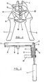
- a plier-stapler is formed by two arms (1) and (2), which include a spring (3), and drag-links fastened at (A) and (B) to each arm (1) and (2) and to the central point, which is not numbered.
- the support part (6) holds the ends of the said drag-links in its slot (15), in front of which there is the stop-part (4).
- the slide-holder-part (5) is folded back, with the control (13) raised and with its opening area in contact with the rivet (B) of the arm (2).
- the stop part (4) avoids the stapless access out once the first staple is located between the arms (1) and (2).
- the loader (7) can be seen, together with the bar (8), the spring (9) and the stop (10) for the spring, in which the staples, in the traditional way, are moved from left to right in accordance with the figure.
- the arm (1), the slide-holder-part (5), the support part (6), the stop part (4), as well as the screw (14) which holds the three parts together, can also be seen.
- the projecting portion (11) of the screw (14) is gripped by the spring (12), which in its turn is fastened to the control (13) of the part (5). It is also possible to appreciate here how the support part (4) becomes lodged in the lower area of the slide-holder-part (5).
- arm (1) in figure 3 shows the hole (18) for the pin that takes in the ends of the two drag-links to be inserted, the hole (19) through which the rivet (B) that fixes the end of its drag-link passes, and the wide rounded area, not numbered, near the portion of the claw (20).
- Arm (2) is similar to arm (1), with the difference that this does not have the said wide area.
- the support part (4) in figure 4 shows the vertical slot hole for the pin that connects with the two arms and the two drag-links, as well as the upper hole (17) which receives the screw (14), the stop-part (4), the support part (6) and the slide-holder-part (5). On the top edge, the stepping (16) can be seen.
- the slide-holder-part can be more clearly appreciated, together with the slide (7), in figures 5 and 6, with the hole (26) for the screw (14) to pass through and the lower prolongation with the hole for the control (13) to be situated.
- the groove or step (24) (and the U shaped upper recess [21] are pointed out).
- FIGS 7 and 8 the schematic behaviour of the tool is observed, in as many rear views of the tool.
- Figure 7 corresponds approximately to figure 2, in which the slide-holder-part (5) has its recess (21) facing upwards, and in which the surface (22) that provides the step (24) butts up against the upper edge (23) of the support part (6), for a staple to be inserted into the space between the jaws, with the spring (12) being compressed.
- Figure 8 refers approximately to figure 1, in which the spring (12) has performed the turning of the slide-holder-part (5), which has rotated over the wide area of arm (1) and has obtained sufficient space on the slide (7) being drawn back from the place where the staple is tightened and fixed.
- the recess (21) is shown here with number (25).
- Figure 9 shows the possibility of fitting the staple slide to a tool, in order to be able to use the tool in a stable manner when the conditions of the area to be staple so permit.
- this means fitting the support part (6) and slide-holder-part (5), for which the corresponding coincident holes are provided, in a position in both parts just as has already been shown in figures 7 and 8, positions (13), which correspond to the superimposing of the holes (13a) and (13b) of parts (5) and (6).
- These holes can be made in any position of both parts, with the only constant that they coincide with the corresponding ones in figure 7, and, therefore, the fixing mechanism can be arranged in any position.
- this positioning is carried out in the place where the control (13) is to be found, for example.
- the outer body (13) can be seen, and the inner bushing (30) welded to the support part (5) in whose interior is situated a shaft (28) pierced by a pin (29) connected to the body (13).
- the bushing (30) has a narrow place (31) and the shaft has a lower circular projection (27), between both of which there is a spring (32).
- the end of the shaft, below the projection (27) is capable of being lodged in the coincident holes in parts (5) and (6).
- the bushing (30) is equipped in its turn with slots (33) and (34) in its front face, figure 10, in which the pin (29) can be placed. These slots are cut to different depths, as has already been mentioned, so that on raising the control (13) and the pin (29) and turning it, this latter can be situated over either slots (33) or (34).
- figures 11 to 16 show a plier-stapler also included in the patent, in its front, rear and side elevations and with the staple slide (46) in the raised position, whereas figures 13 to 16 show the same except with the slide (46) in the folded back position.
- This tool is equipped with arms (39) and drag-links (45) which run in a slot of the support part (36), as well as the claw return spring (43) and the upper staple slide (46).
- arms (39) and drag-links (45) which run in a slot of the support part (36), as well as the claw return spring (43) and the upper staple slide (46).
- the arms (39) are articulated in their lower part by means of the drag-links (40) on the lower end of the slide-holder-part (48), which shows the slot (47) that slides on the pin (49) which connects (36) and (48).
- the tool is applied to staples of a general "U" shape, on which by the effect of tightening the jaws, the wings or sides of the staple take a ringed shape, triangular shape, etc., with one overlapping over the other
Landscapes
- Mechanical Engineering (AREA)
- Engineering & Computer Science (AREA)
- Portable Nailing Machines And Staplers (AREA)
- Nonmetallic Welding Materials (AREA)
- Polysaccharides And Polysaccharide Derivatives (AREA)
- Steroid Compounds (AREA)
- Glass Compositions (AREA)
- Organic Low-Molecular-Weight Compounds And Preparation Thereof (AREA)
- Pharmaceuticals Containing Other Organic And Inorganic Compounds (AREA)
- Harvesting Machines For Specific Crops (AREA)
- Harvester Elements (AREA)
- Surgical Instruments (AREA)
- Gripping Jigs, Holding Jigs, And Positioning Jigs (AREA)
- Scissors And Nippers (AREA)
Claims (6)
Priority Applications (1)
| Application Number | Priority Date | Filing Date | Title |
|---|---|---|---|
| AT86500002T ATE52956T1 (de) | 1985-10-29 | 1986-10-28 | Klammerbiegezange. |
Applications Claiming Priority (2)
| Application Number | Priority Date | Filing Date | Title |
|---|---|---|---|
| ES1985289930U ES289930Y (es) | 1985-10-29 | 1985-10-29 | Alicate grapador |
| ES289930 | 1985-10-29 |
Publications (2)
| Publication Number | Publication Date |
|---|---|
| EP0226525A1 EP0226525A1 (de) | 1987-06-24 |
| EP0226525B1 true EP0226525B1 (de) | 1990-05-23 |
Family
ID=8437999
Family Applications (1)
| Application Number | Title | Priority Date | Filing Date |
|---|---|---|---|
| EP86500002A Expired - Lifetime EP0226525B1 (de) | 1985-10-29 | 1986-10-28 | Klammerbiegezange |
Country Status (6)
| Country | Link |
|---|---|
| EP (1) | EP0226525B1 (de) |
| AT (1) | ATE52956T1 (de) |
| DE (1) | DE3671401D1 (de) |
| DK (1) | DK163484C (de) |
| ES (1) | ES289930Y (de) |
| GR (1) | GR3000650T3 (de) |
Families Citing this family (5)
| Publication number | Priority date | Publication date | Assignee | Title |
|---|---|---|---|---|
| ES2011706A6 (es) * | 1988-11-18 | 1990-02-01 | Simes Senco Sa | Dispositivo convertidor de alicate cose-grapas para funcion fija o escamoteable de la pista de grapas. |
| GB8908581D0 (en) * | 1989-04-15 | 1989-06-01 | Eadie Brian | Tool for fitting components to articles |
| GB9004806D0 (en) * | 1990-03-03 | 1990-04-25 | Eadie Brian K M | Beak bit applicator |
| FR2881922B1 (fr) * | 2005-02-17 | 2007-04-13 | Vincent Toussaint | Dispositif de pince pour la pose d'anneaux anti-picage au niveau du bec de gallinaces |
| CN108482730B (zh) * | 2018-04-28 | 2024-01-23 | 烟台梦现自动化设备有限公司 | 一种全自动水果网袋套袋系统 |
Family Cites Families (2)
| Publication number | Priority date | Publication date | Assignee | Title |
|---|---|---|---|---|
| US2689955A (en) * | 1947-08-25 | 1954-09-28 | Heller Company | Hug ring pliers |
| ES263128Y (es) * | 1982-02-11 | 1983-02-01 | Alicate cose-grapas. |
-
1985
- 1985-10-29 ES ES1985289930U patent/ES289930Y/es not_active Expired
-
1986
- 1986-10-28 DK DK516186A patent/DK163484C/da active
- 1986-10-28 DE DE8686500002T patent/DE3671401D1/de not_active Expired - Fee Related
- 1986-10-28 AT AT86500002T patent/ATE52956T1/de not_active IP Right Cessation
- 1986-10-28 EP EP86500002A patent/EP0226525B1/de not_active Expired - Lifetime
-
1990
- 1990-07-18 GR GR90400496T patent/GR3000650T3/el unknown
Also Published As
| Publication number | Publication date |
|---|---|
| DK163484C (da) | 1992-08-24 |
| GR3000650T3 (en) | 1991-09-27 |
| DE3671401D1 (de) | 1990-06-28 |
| ES289930Y (es) | 1987-06-01 |
| DK163484B (da) | 1992-03-09 |
| ES289930U (es) | 1986-10-01 |
| DK516186A (da) | 1987-04-30 |
| ATE52956T1 (de) | 1990-06-15 |
| DK516186D0 (da) | 1986-10-28 |
| EP0226525A1 (de) | 1987-06-24 |
Similar Documents
| Publication | Publication Date | Title |
|---|---|---|
| US3873016A (en) | Pliers type surgical stapler for joining disunited skin or fascia | |
| AU598920B2 (en) | An improved anvil and driver assembly for a surgical skin stapling instrument | |
| US4619391A (en) | Surgical stapling instrument | |
| US4526174A (en) | Staple and cartridge for use in a tissue stapling device and a tissue closing method | |
| US4265226A (en) | Incision closing method | |
| JPH0640879B2 (ja) | 組織結合用外科用具 | |
| DE4434864A1 (de) | Chirurgischer Klammerapplikator | |
| JP2001509088A (ja) | 手持ち式多目的器具 | |
| JP4160172B2 (ja) | 直立型締結具駆動工具への締結具供給装置 | |
| EP0790103A2 (de) | Eintreibgerät für Befestigungsmittel | |
| EP0226525B1 (de) | Klammerbiegezange | |
| EP0286921A1 (de) | Hämostatische Klammervorrichtung zum Anbringen mehrerer Klammern | |
| JPH012640A (ja) | 複数個の止血鉗子を装着するための止血鉗子アプリケータ | |
| JPS6236694B2 (de) | ||
| JPS5897350A (ja) | 圧力に応動して作用空隙が制御される外科用止め器具 | |
| EP0302093A1 (de) | Gerät zum anbringen von venenmanschetten, magazin und manschetten hierfür | |
| JPS61501825A (ja) | 可変留め具列をもつ外科用留め具付け装置 | |
| CA2222518A1 (en) | Fastener length adjustable canister-type magazine for a fastener driving tool | |
| JPH07502696A (ja) | モジュラーチューブ組立装置 | |
| EP0002619A2 (de) | Kennzeichnungsmarke und Befestigungsgerät dafür | |
| US2455557A (en) | Rod clamp tool | |
| US2267990A (en) | Stapling machine | |
| US5397045A (en) | Tape stapler | |
| WO1994011131A1 (en) | Ring fastener package and portable tool | |
| US12454041B2 (en) | Manually operable pressing tool |
Legal Events
| Date | Code | Title | Description |
|---|---|---|---|
| PUAI | Public reference made under article 153(3) epc to a published international application that has entered the european phase |
Free format text: ORIGINAL CODE: 0009012 |
|
| AK | Designated contracting states |
Kind code of ref document: A1 Designated state(s): AT BE CH DE FR GB GR IT LI LU NL SE |
|
| 17P | Request for examination filed |
Effective date: 19871130 |
|
| 17Q | First examination report despatched |
Effective date: 19890214 |
|
| GRAA | (expected) grant |
Free format text: ORIGINAL CODE: 0009210 |
|
| AK | Designated contracting states |
Kind code of ref document: B1 Designated state(s): AT BE CH DE FR GB GR IT LI LU NL SE |
|
| PG25 | Lapsed in a contracting state [announced via postgrant information from national office to epo] |
Ref country code: SE Effective date: 19900523 Ref country code: NL Effective date: 19900523 Ref country code: LI Effective date: 19900523 Ref country code: CH Effective date: 19900523 Ref country code: BE Effective date: 19900523 Ref country code: AT Effective date: 19900523 |
|
| REF | Corresponds to: |
Ref document number: 52956 Country of ref document: AT Date of ref document: 19900615 Kind code of ref document: T |
|
| ITF | It: translation for a ep patent filed | ||
| REF | Corresponds to: |
Ref document number: 3671401 Country of ref document: DE Date of ref document: 19900628 |
|
| ET | Fr: translation filed | ||
| REG | Reference to a national code |
Ref country code: CH Ref legal event code: PL |
|
| NLV1 | Nl: lapsed or annulled due to failure to fulfill the requirements of art. 29p and 29m of the patents act | ||
| PG25 | Lapsed in a contracting state [announced via postgrant information from national office to epo] |
Ref country code: GB Effective date: 19901028 |
|
| PG25 | Lapsed in a contracting state [announced via postgrant information from national office to epo] |
Ref country code: LU Free format text: LAPSE BECAUSE OF NON-PAYMENT OF DUE FEES Effective date: 19901031 |
|
| REG | Reference to a national code |
Ref country code: GR Ref legal event code: FG4A Free format text: 3000650 |
|
| PLBE | No opposition filed within time limit |
Free format text: ORIGINAL CODE: 0009261 |
|
| STAA | Information on the status of an ep patent application or granted ep patent |
Free format text: STATUS: NO OPPOSITION FILED WITHIN TIME LIMIT |
|
| 26N | No opposition filed | ||
| GBPC | Gb: european patent ceased through non-payment of renewal fee | ||
| PG25 | Lapsed in a contracting state [announced via postgrant information from national office to epo] |
Ref country code: DE Effective date: 19910702 |
|
| PGFP | Annual fee paid to national office [announced via postgrant information from national office to epo] |
Ref country code: GR Payment date: 19910925 Year of fee payment: 6 |
|
| ITTA | It: last paid annual fee | ||
| PGFP | Annual fee paid to national office [announced via postgrant information from national office to epo] |
Ref country code: FR Payment date: 19920930 Year of fee payment: 7 |
|
| PG25 | Lapsed in a contracting state [announced via postgrant information from national office to epo] |
Ref country code: GR Free format text: THE PATENT HAS BEEN ANNULLED BY A DECISION OF A NATIONAL AUTHORITY Effective date: 19930430 |
|
| PG25 | Lapsed in a contracting state [announced via postgrant information from national office to epo] |
Ref country code: FR Effective date: 19940630 |
|
| REG | Reference to a national code |
Ref country code: FR Ref legal event code: ST |
|
| REG | Reference to a national code |
Ref country code: GR Ref legal event code: MM2A Free format text: 3000650 |
|
| PG25 | Lapsed in a contracting state [announced via postgrant information from national office to epo] |
Ref country code: IT Free format text: LAPSE BECAUSE OF NON-PAYMENT OF DUE FEES;WARNING: LAPSES OF ITALIAN PATENTS WITH EFFECTIVE DATE BEFORE 2007 MAY HAVE OCCURRED AT ANY TIME BEFORE 2007. THE CORRECT EFFECTIVE DATE MAY BE DIFFERENT FROM THE ONE RECORDED. Effective date: 20051028 |