EP0226731B1 - Dispositif pour diminuer l'émission de la matière nocive dans les gaz d'échappement des installations de combustion - Google Patents
Dispositif pour diminuer l'émission de la matière nocive dans les gaz d'échappement des installations de combustion Download PDFInfo
- Publication number
- EP0226731B1 EP0226731B1 EP86113741A EP86113741A EP0226731B1 EP 0226731 B1 EP0226731 B1 EP 0226731B1 EP 86113741 A EP86113741 A EP 86113741A EP 86113741 A EP86113741 A EP 86113741A EP 0226731 B1 EP0226731 B1 EP 0226731B1
- Authority
- EP
- European Patent Office
- Prior art keywords
- media
- storage
- hood
- heat exchanger
- hoods
- Prior art date
- Legal status (The legal status is an assumption and is not a legal conclusion. Google has not performed a legal analysis and makes no representation as to the accuracy of the status listed.)
- Expired - Lifetime
Links
- 239000003546 flue gas Substances 0.000 title claims description 36
- 238000002485 combustion reaction Methods 0.000 title claims description 23
- 230000001473 noxious effect Effects 0.000 title claims 2
- 230000001172 regenerating effect Effects 0.000 claims description 48
- 238000004140 cleaning Methods 0.000 claims description 26
- UGFAIRIUMAVXCW-UHFFFAOYSA-N Carbon monoxide Chemical compound [O+]#[C-] UGFAIRIUMAVXCW-UHFFFAOYSA-N 0.000 claims description 24
- 239000007789 gas Substances 0.000 claims description 19
- 238000000034 method Methods 0.000 claims description 9
- 238000000926 separation method Methods 0.000 claims description 7
- 238000001816 cooling Methods 0.000 claims description 5
- 230000001105 regulatory effect Effects 0.000 claims description 4
- 238000003303 reheating Methods 0.000 claims description 3
- 238000011144 upstream manufacturing Methods 0.000 claims description 3
- 238000005260 corrosion Methods 0.000 claims description 2
- 230000007797 corrosion Effects 0.000 claims description 2
- 230000001276 controlling effect Effects 0.000 claims 1
- 238000006477 desulfuration reaction Methods 0.000 description 12
- 230000023556 desulfurization Effects 0.000 description 12
- MWUXSHHQAYIFBG-UHFFFAOYSA-N nitrogen oxide Inorganic materials O=[N] MWUXSHHQAYIFBG-UHFFFAOYSA-N 0.000 description 12
- 238000005406 washing Methods 0.000 description 10
- 238000005338 heat storage Methods 0.000 description 6
- 238000010438 heat treatment Methods 0.000 description 6
- 238000005192 partition Methods 0.000 description 6
- 238000006722 reduction reaction Methods 0.000 description 6
- 238000007789 sealing Methods 0.000 description 5
- BIGPRXCJEDHCLP-UHFFFAOYSA-N ammonium bisulfate Chemical compound [NH4+].OS([O-])(=O)=O BIGPRXCJEDHCLP-UHFFFAOYSA-N 0.000 description 3
- 238000013461 design Methods 0.000 description 3
- 238000012546 transfer Methods 0.000 description 3
- 238000004891 communication Methods 0.000 description 2
- 238000010276 construction Methods 0.000 description 2
- 239000000428 dust Substances 0.000 description 2
- 238000010304 firing Methods 0.000 description 2
- XLYOFNOQVPJJNP-UHFFFAOYSA-N water Substances O XLYOFNOQVPJJNP-UHFFFAOYSA-N 0.000 description 2
- 235000008733 Citrus aurantifolia Nutrition 0.000 description 1
- -1 NH 4 HS0 4 Chemical compound 0.000 description 1
- 235000011941 Tilia x europaea Nutrition 0.000 description 1
- 238000010521 absorption reaction Methods 0.000 description 1
- 230000002411 adverse Effects 0.000 description 1
- 238000010531 catalytic reduction reaction Methods 0.000 description 1
- 239000007795 chemical reaction product Substances 0.000 description 1
- 150000001875 compounds Chemical class 0.000 description 1
- 238000011161 development Methods 0.000 description 1
- 230000000694 effects Effects 0.000 description 1
- 239000003344 environmental pollutant Substances 0.000 description 1
- 229910052602 gypsum Inorganic materials 0.000 description 1
- 239000010440 gypsum Substances 0.000 description 1
- 238000009434 installation Methods 0.000 description 1
- 239000004571 lime Substances 0.000 description 1
- 231100000719 pollutant Toxicity 0.000 description 1
- 150000003112 potassium compounds Chemical class 0.000 description 1
- 230000002787 reinforcement Effects 0.000 description 1
- 239000007921 spray Substances 0.000 description 1
- XTQHKBHJIVJGKJ-UHFFFAOYSA-N sulfur monoxide Chemical class S=O XTQHKBHJIVJGKJ-UHFFFAOYSA-N 0.000 description 1
- 229910052815 sulfur oxide Inorganic materials 0.000 description 1
Images

Classifications
-
- B—PERFORMING OPERATIONS; TRANSPORTING
- B01—PHYSICAL OR CHEMICAL PROCESSES OR APPARATUS IN GENERAL
- B01D—SEPARATION
- B01D53/00—Separation of gases or vapours; Recovering vapours of volatile solvents from gases; Chemical or biological purification of waste gases, e.g. engine exhaust gases, smoke, fumes, flue gases, aerosols
- B01D53/34—Chemical or biological purification of waste gases
-
- F—MECHANICAL ENGINEERING; LIGHTING; HEATING; WEAPONS; BLASTING
- F23—COMBUSTION APPARATUS; COMBUSTION PROCESSES
- F23J—REMOVAL OR TREATMENT OF COMBUSTION PRODUCTS OR COMBUSTION RESIDUES; FLUES
- F23J15/00—Arrangements of devices for treating smoke or fumes
Definitions
- the invention is concerned with flue gas cleaning in combustion plants, that is to say with secondary measures which contribute to the reduction of S0 2 and NOx emissions in combustion plants of conventional design.
- the subject matter of the invention is a device for reducing harmful gas during the operation of combustion plants, for example for steam generation, which is useful not only for removing SO 2 but also for NOx from flue gases.
- Such a device for reducing harmful gases during the operation of combustion plants consists of wet and / or dry working reactors and associated regenerative heat exchangers, the regenerative heat exchangers serving either for cooling and reheating or for preheating and re-cooling the flue gas stream.
- So-called multi-flow regenerative heat exchangers reach the z. B. from DE-A-3 238 941 known type for use, as they are used for the separate heating of two media streams and in which the storage masses are divided so concentrically for this purpose that the heat-transferring as well as the heat-absorbing media in each case two separate, parallel streams can be passed through the storage masses.
- Regenerative heat exchangers such as those developed to achieve a separate controllability of the primary and secondary air temperatures and quantities are therefore used in devices for reducing harmful gases when operating combustion plants.
- controllable heating of the primary and secondary air is achieved in that the two air streams are guided concentrically to one another through separate spaces of the storage masses and their temperatures and pressures are regulated independently of one another.
- washing processes e.g. with the end product gypsum, or the so-called spray absorption process are used to remove S0 2 from the flue gases from combustion plants
- catalytic reduction with NH 3 has so far been used for NOx removal from the flue gases from combustion plants so-called SCR reactors are used.
- SCR reactors are installed in the firing systems of steam generators on the one hand between the economizer and the air preheater, i.e. before the flue gas desulfurization or S0 2 removal, or behind the flue gas desulfurization or S0 2 removal, i.e. in front of the chimney.
- the flue gas is cooled as raw gas before washing and then reheated as clean gas.
- Regenerative heat exchangers are used for this purpose. Such regenerative heat exchangers are endangered on the one hand by clogging their heat storage masses with deposits which, when arranged with flue gas desulphurization, consist of lime compounds and flying dust, while additionally containing ammonium bisulfate, i.e. NH 4 HS0 4 , when arranged with the SCR reactor.
- flue gas desulphurization consist of lime compounds and flying dust
- ammonium bisulfate i.e. NH 4 HS0 4
- the flue gas desulfurization also has the disadvantage of temperature changes which occur during part-load operation of the furnace, because the water balance is adversely affected by the lowering of the raw gas inlet temperature in the scrubber.
- the object of the invention is to enable loading of the storage masses in a constant alternation on the one hand with both parallel flows of the heat-transferring medium and on the other hand with both parallel flows of the heat-absorbing medium and to ensure that each individual flow of media is influenced independently of all other media flows leaves.
- the subdivision of the heating surfaces or storage mass can take place in such a way that for each of the two parallel flows of the heat-transfer medium and the heat-absorbing medium half the capacity of the same is available, so that one area is regeneratively closed and completely washed -Heat exchanger in the other area of the same an operation with 60 to 65% of the nominal load is made possible.
- the design of the device according to the invention can be chosen such that only that part of the storage masses which is shut off against media supply can be subjected to a wet or thermal cleaning process.
- the wet cleaning takes place in such a way that the corresponding area is first separated from the hot medium of cooling and is then washed with water after being shut off from the cold medium. This area is then brought back up to operating temperature by opening the corresponding butterfly valves.
- the thermal cleaning takes place in that the storage masses are overheated or supercooled compared to their normal operating state. In both cases, this leads to a change in the state of matter of the covering, for example as ammonium bisulfate (NH4 HS04), so that the heating surfaces can consequently be cleaned well.
- NH4 HS04 ammonium bisulfate
- a nominal value control of the gas temperature can also be brought about with the device according to the invention during part-load operation of the furnace.
- the flows of both the heat-transferring medium and the heat-absorbing medium are conducted separately in parallel at least on one side of the regenerative heat exchanger outside the storage masses, because only in this way does one optimal throughput control of the media can be achieved through the storage masses of the regenerative heat exchanger.
- all of the current separations for both media located outside the storage masses are arranged on the same side of the heat exchanger and thereby enable the device to be produced with a relatively small amount of construction.
- the current separations consist of channels and / or hoods, in each of which, at a distance from the storage mass, throttle and / or shut-off valves are seated, each of which can be actuated independently of one another. If a larger number of throttle and / or butterfly valves is provided in each of the channels and / or in each of the hoods, which can be actuated individually and independently of one another, optimum regulation of the gas temperatures to nominal values within each sub-range of the storage masses of the regenerative Heat exchanger possible.
- the effectiveness of a device according to the invention can also be increased in that, according to claim 6, the cleaning devices are assigned to the upper side of the storage masses in the vertically arranged regenerative heat exchanger.
- the current separations for the media flows are assigned to the side of the regenerative heat exchanger which are not burdened by corrosion or high temperatures.
- the rotationally symmetrical temperature profile in the storage masses of the regenerative heat exchanger also allows easy adjustment of the sealing system.
- FIG. 1 of the drawing the structure of a so-called multi-flow regenerative heat exchanger 1 is shown, which contains the storage masses 3 with their heating surfaces in a vertical arrangement in a stationary housing 2.
- the storage masses of the regenerative heat exchanger are concentrically divided into two storage mass areas 3a and 3b by an installed partition 4, each of which comprises 50% of the heating surfaces.
- An outer ring area of the storage masses 3 contains the storage mass area 3a, while an inner ring area thereof contains the storage mass area 3b.
- two media supply hoods 5 and 6 as well as two media discharge hoods 7 and 8 are connected.
- the media supply hoods 5 and 6 are in constant communication with two separate feed channels 9 and 10, while two separate channels 11 and 12 are connected to the media discharge hoods 7 and 8.
- a media feed hood 13 and a media discharge hood 14 are in turn assigned to the other end of the stationary housing 2, the former connecting to a channel 15, while the second is connected to a channel 16.
- the two media supply hoods 5 and 6 and the media discharge hood 14 are each designed as ring sector-shaped rotary hoods which are connected to one another by a shaft 17 in rotary drive connection.
- the feed hood 5 covers the inner storage mass ring area 3b of the stationary storage masses 3, while the media feed hood 6 rotates along the outer storage mass area 3a thereof.
- the sections 8a of the media discharge hood 8 associated with the stationary storage masses 3 in the region of the concentric partition 4 are the two Media feed hoods 5 and 6 connected so that it can perform a rotational movement together with these.
- a rotatable section 8a of the media discharge hood 8 is followed by a stationary section 8b thereof.
- the media supply hood 13 comprises the entire, upward-facing end face of the storage masses 3, that is to say the storage mass regions 3a and 3b
- the media discharge hood 7 is only assigned to the lower end face of the storage mass region 3a
- the media discharge hood 8 comprises the downward end face of the storage mass area 3b.
- the media feed hoods 5 and 6 and the section 8a of the media discharge hood 8 are rotatably accommodated within the stationary media discharge hood 7, while the media discharge hood 14 rotates within the stationary media feed hood 13.
- the two stationary media feed channels 9 and 10 are connected to the rotatable media feed hoods 5 and 6, these sitting concentrically one inside the other.
- throttle and / or shut-off flaps 21 and 22 are installed in each of the media supply channels 9 and 10 and can be actuated independently of one another.
- the media feed channel 9 can be selectively released and shut off and its passage cross section can also be varied.
- the throttle and / or shut-off flaps 22 can also be used to selectively shut off or open the media feed channel 10, and also vary its effective passage cross section.
- the rotatable media discharge hood 14 also adjoins the stationary media discharge channel 16 by means of coaxially overlapping sealing aprons.
- the media discharge channels 11 and 12, which are in flow communication with the two media discharge hoods 7 and 8, are also equipped with shut-off and / or throttle valves 24 and 25 downstream of the media discharge hoods 7 and 8, with the aid of which their passage cross-section can optionally be released and can shut off, but can also be varied in its effective dimensions.
- the above described reinforcement of the regenerative heat exchanger means that two parallel flows of both the heat transfer medium and the heat absorbing medium can be conducted separately from one another through the heat storage masses 3, namely on the one hand through the storage mass area 3 a and on the other hand through the storage mass area 3 b.
- the flow of the heat-transferring medium passed through the media feed channel 9 and the media-feed hood 5 acts on the storage mass area 3b of the stationary storage masses 3, while the flow of the heat-transferring medium passed through the media feed channel 10 and the media feed hood 6 Storage mass area 3a applied.
- Both heat-transferring media streams are then taken up together at the upper end of the stationary storage masses 3 by the rotatable media discharge hood 14 and guided by this into the media discharge channel 16.
- the other medium passes through the media feed channel 15 into the stationary media feed hood 13 to the upper end of the heat storage masses 3 and is divided there by the concentric partition 4 as it passes through the heat storage masses 3 into two separate media streams, one through the storage mass area 3a and the other goes through the storage mass area 3b.
- the two separate media streams are each in heat exchange with the storage mass area 3a or the storage mass area 3b, before they are separated from one another in the annular space of the media discharge hood 7 and in the media -Leave hood 8 and enter the media discharge channels 11 and 12 from there.
- the flow of the heat-transmitting medium through the storage mass area 2b can optionally be released and blocked, but its throughput can also be varied.
- the throttle and / or shut-off flaps 22 on the other hand, the flow of the heat-transferring medium through the storage mass area 3 a can be shut off and released, as well as throttled in terms of quantity.
- shut-off flaps 25 By actuating the shut-off flaps 25, it is possible to selectively block and release the passage of the heat-absorbing medium through the storage mass area 3 a, and also to throttle the quantity.
- the throttle and / or shut-off flaps 24 can also be used to selectively block or release the passage of the heat-absorbing medium through the storage mass area 3b, as well as to reduce the quantity, although the current separation of the heat-absorbing medium only within the storage masses 3, namely by the partition 4 between the storage mass areas 3a and 3b takes place.
- Cleaning or washing devices 28a and 28b are arranged and designed on the upper side of the regenerative heat exchanger 1 in such a way that they can act separately on the two storage mass regions 3a and 3b of the heat storage masses 3 with the washing or cleaning medium which the Undesired deposits formed in the storage masses are removed, which - depending on the arrangement of the regenerative heat exchanger 1 in the system of the gas cleaning system - can either consist only of potassium compounds and flying dust or additionally of ammonium bisulfate.
- the washing and / or cleaning devices 28a, 28b are advantageously arranged outside the rotatable media discharge hood 14, but inside the media feed hood 13, in such a way that they rotate together with the media discharge hood 14 within the media feed hood 13 and thereby coat the entire end face of the heat storage masses 3 during their movement. It is advantageous that in each case in the installation area of the washing and / or cleaning devices 28a, 28b a partition or a shield 29 is provided which connects to the concentric partition 4 in the housing 1 and thereby the effective areas of the washing and / or cleaning devices 28a and 28b shields each other.
- washing and / or cleaning device 28a or 28b is put into operation, which is the storage mass area 3a or 3b which has just stopped, ie is still acted upon by two currents moving in opposite directions.
- each individual storage mass area 3a and 3b of the regenerative heat exchanger 1 is in contact with both the heat-transferring and the heat-absorbing media wide limits, a regulation of the media temperatures to nominal values can be achieved, the most varied part-load operating conditions of the furnace are optimally adapted.
- the storage masses 3 can subdivide the storage masses 3 into more than two concentrically nested storage mass areas, preferably into three storage mass areas, and then to assign them a corresponding number of media supply and discharge hoods, at least on the hot side .
- the media feed and discharge hoods assigned to the middle storage mass area can then be designed such that with their help this middle storage mass area can be optionally connected to the inner or the outer storage mass area. While in each case one area of the storage masses 3 is subjected to a washing or cleaning process, the other storage mass areas can then remain in operation, it then also being possible to apply them with more than 65% of the nominal load of the gas cleaning system in question. In this case, the cleaning process in the medium-switchable storage mass area can always be carried out when the large combustion system is running in a part-load operation, which is at most 50% of the nominal load.
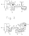
- FIGS. 2 and 3 of the drawing show purely schematically two differently constructed combustion plants, in each of which an apparatus according to the invention for reducing harmful gases is integrated.
- the economizer 31 is connected to the boiler 30.
- the so-called SCR reactor 32 for nitrogen oxide or NO x removal from the flue gases is installed after the economizer 31.
- the air preheater 33 for the combustion air of the boiler 30 Behind the air preheater 33 there is the dedusting system 34 and a flue gas blower 35 connected downstream of it.
- the regenerative heat exchanger 1 designed and operable according to the invention is installed in the combustion system according to FIG. 2, which is acted upon by the flue gases and cools them down, before they enter the flue gas desulfurization system 36 for S0 2 removal.
- the regenerative heat exchanger 1 is still acted upon by the flue gases emerging from the flue gas desulfurization system 36 for reheating.
- the large combustion plant according to FIG. 3 differs from that according to FIG. 2 on the one hand in that the SCR reactor 32 for nitrogen oxide or NOx reduction is installed behind the flue gas desulfurization plant 36, while on the other hand the regenerative heat exchanger 1 according to the invention is also located there is located behind the flue gas desulfurization system 36.
- the regenerative heat exchanger 1 is acted on the one hand by the flue gases coming from the desulfurization system 36 for preheating, which then enter the SCR reactor 32.
- the flue gas coming from the SCR reactor 32 is fed to the regenerative heat exchanger 1 there for cooling before it reaches the chimney of the furnace.
- a regenerative heat exchanger 37 can also be installed upstream of the flue gas desulfurization system 36, which may have the same design and mode of operation as the regenerative heat exchanger 1.
- This regenerative heat exchanger 37 is acted upon by the flue gases on the one hand before they enter the flue gas desulfurization system 36. On the other hand, it can be charged with the flue gases that have previously flowed through the SCR reactor 32 from the regenerative heat exchanger 1.
Landscapes
- Engineering & Computer Science (AREA)
- Chemical & Material Sciences (AREA)
- General Chemical & Material Sciences (AREA)
- Environmental & Geological Engineering (AREA)
- Biomedical Technology (AREA)
- Analytical Chemistry (AREA)
- Health & Medical Sciences (AREA)
- Oil, Petroleum & Natural Gas (AREA)
- Chemical Kinetics & Catalysis (AREA)
- Mechanical Engineering (AREA)
- General Engineering & Computer Science (AREA)
- Treating Waste Gases (AREA)
- Air Supply (AREA)
- Chimneys And Flues (AREA)
Claims (8)
Applications Claiming Priority (2)
| Application Number | Priority Date | Filing Date | Title |
|---|---|---|---|
| DE3537478 | 1985-10-22 | ||
| DE19853537478 DE3537478A1 (de) | 1985-10-22 | 1985-10-22 | Vorrichtung zur schadgasminderung beim betrieb von feuerungsanlagen |
Publications (2)
| Publication Number | Publication Date |
|---|---|
| EP0226731A1 EP0226731A1 (fr) | 1987-07-01 |
| EP0226731B1 true EP0226731B1 (fr) | 1990-02-07 |
Family
ID=6284124
Family Applications (1)
| Application Number | Title | Priority Date | Filing Date |
|---|---|---|---|
| EP86113741A Expired - Lifetime EP0226731B1 (fr) | 1985-10-22 | 1986-10-03 | Dispositif pour diminuer l'émission de la matière nocive dans les gaz d'échappement des installations de combustion |
Country Status (5)
| Country | Link |
|---|---|
| EP (1) | EP0226731B1 (fr) |
| JP (1) | JPS6295120A (fr) |
| AU (1) | AU597910B2 (fr) |
| DE (2) | DE3537478A1 (fr) |
| ES (1) | ES2012752B3 (fr) |
Families Citing this family (2)
| Publication number | Priority date | Publication date | Assignee | Title |
|---|---|---|---|---|
| DE4313861A1 (de) * | 1993-04-28 | 1994-11-03 | Rothemuehle Brandt Kritzler | Anlage zur Stickoxidminderung bei Feuerungsabgasen |
| US5509461A (en) * | 1993-12-02 | 1996-04-23 | The Babcock & Wilcox Company | Gas-gas heater protection system and method |
Family Cites Families (7)
| Publication number | Priority date | Publication date | Assignee | Title |
|---|---|---|---|---|
| US2429880A (en) * | 1945-01-05 | 1947-10-28 | Carnegie Illinois Steel Corp | Method for operating sectionable heat exchangers |
| FR1451038A (fr) * | 1965-10-22 | 1966-06-24 | Appbau Rothemuehle Brandt | Perfectionnements à des échangeurs récupérateurs de chaleur |
| US3997294A (en) * | 1973-11-24 | 1976-12-14 | Apparatebau Rothemuhle Brandt & Kritzler | Device for treating gases |
| US4114680A (en) * | 1977-04-25 | 1978-09-19 | Apparatebau Rothemuhle Brandt & Kritzler | Regenerative air preheater for separate preheating of two or more air-or gas streams |
| DE3227553C2 (de) * | 1982-07-23 | 1986-04-24 | Thyssen Industrie Ag, 4300 Essen | Vorrichtung zur trockenen Rauchgasreinigung |
| DE3238941C2 (de) * | 1982-10-21 | 1984-11-22 | Apparatebau Rothemühle Brandt + Kritzler GmbH, 5963 Wenden | Verfahren zur Wiederaufwärmung bzw. Vortrocknung von durch eine Rauchgaswäsche aus Rohgas einer Dampfkesselanlage gewonnenem Reingas sowie Regenerativ-Wärmeaustauscher zur Ausübung des Verfahrens |
| DE3341021A1 (de) * | 1983-11-12 | 1985-05-23 | Kraftanlagen Ag, 6900 Heidelberg | Verfahren und einrichtung zur wiederaufheizung der reingase im anschluss an die nassreinigung von rohgasen |
-
1985
- 1985-10-22 DE DE19853537478 patent/DE3537478A1/de not_active Withdrawn
-
1986
- 1986-10-03 ES ES86113741T patent/ES2012752B3/es not_active Expired - Lifetime
- 1986-10-03 EP EP86113741A patent/EP0226731B1/fr not_active Expired - Lifetime
- 1986-10-03 DE DE8686113741T patent/DE3668981D1/de not_active Expired - Fee Related
- 1986-10-08 AU AU63669/86A patent/AU597910B2/en not_active Ceased
- 1986-10-21 JP JP61248559A patent/JPS6295120A/ja active Pending
Also Published As
| Publication number | Publication date |
|---|---|
| AU6366986A (en) | 1987-04-30 |
| AU597910B2 (en) | 1990-06-14 |
| JPS6295120A (ja) | 1987-05-01 |
| DE3668981D1 (de) | 1990-03-15 |
| DE3537478A1 (de) | 1987-04-23 |
| ES2012752B3 (es) | 1990-04-16 |
| EP0226731A1 (fr) | 1987-07-01 |
Similar Documents
| Publication | Publication Date | Title |
|---|---|---|
| DE3517987C2 (fr) | ||
| DE2733408B2 (de) | Rauchgaszug einer Kesselanlage | |
| DE4014415C2 (de) | Vorrichtung zur katalytischen Oxidation der schädlichen Bestandteile in einem abgekühlten Trägergas eines verfahrenstechnischen Prozesses | |
| DE3238941C2 (de) | Verfahren zur Wiederaufwärmung bzw. Vortrocknung von durch eine Rauchgaswäsche aus Rohgas einer Dampfkesselanlage gewonnenem Reingas sowie Regenerativ-Wärmeaustauscher zur Ausübung des Verfahrens | |
| DE3140406A1 (de) | Regenerativ-waermeaustauscher zur getrennten aufwaermung zweier parallel gefuehrter stroeme eines waermeaufnehmenden mediums durch ein waermeabgebendes medium | |
| DD218661A5 (de) | Verfahren und vorrichtung zum wiederaufheizen entschwefelter rauchgase | |
| EP0226731B1 (fr) | Dispositif pour diminuer l'émission de la matière nocive dans les gaz d'échappement des installations de combustion | |
| DE2844521A1 (de) | Rekuperator | |
| EP2023070B1 (fr) | Echangeur thermique régénératif, joint radial destiné à l'utilisation pour celui-ci et procédé destiné à la séparation de milieux gazeux dans un échangeur thermique régénératif | |
| DE19905733A1 (de) | Verfahren und Anlage zur Reinigung von mit Stickoxiden beladenen Abgasen | |
| DE3782391T2 (de) | Verfahren bei der wirbelschichtverbrennung. | |
| DE4013484C2 (de) | Verfahren und Anlage zur Minderung von Schadgasemissionen bei Wärmekraftwerken | |
| DE3304455A1 (de) | Heizkessel | |
| EP0233998B1 (fr) | Dispositif de réglage à une valeur donnée de la température des fumées | |
| DE102012206704B4 (de) | Abreinigung von mit mindestens einem Prozessfluid durchströmten Kanälen | |
| DE102010012006A1 (de) | Wärmetauscher für eine thermische Abluftreinigungsanlage und Verfahren zum Reinigen eines Abluftstroms | |
| DE4207667A1 (de) | Waermekraftmaschine mit abgaswaermetauscher | |
| DE19926405C2 (de) | Verfahren zur thermischen Regeneration des Wärmetauschermaterials einer regenerativen Nachverbrennungsvorrichtung | |
| EP0191441A1 (fr) | Procédé pour éliminer des composants indésirables d'un gaz de fumée | |
| DE2537951C3 (de) | Vorrichtung zum Vorwärmen und Calcinieren körniger und stückiger Materialien | |
| DE19707340C2 (de) | Verfahren und Anordnung zum Warten von Anlagenteilen in Rauchgassträngen eines Kohlkraftwerkes | |
| DE19644914C2 (de) | Mühlenluftvorwärmer | |
| EP0055798B1 (fr) | Refroidisseur pour le refroidissement à sec de coke | |
| DD242965A5 (de) | Vorrichtung und verfahren zur entfernung unerwuenschter gasfoermiger bestandteile aus einem rauchgas | |
| AT233029B (de) | Verfahren und Einrichtung zur Rationalisierung des Betriebes von Industrieöfen |
Legal Events
| Date | Code | Title | Description |
|---|---|---|---|
| PUAI | Public reference made under article 153(3) epc to a published international application that has entered the european phase |
Free format text: ORIGINAL CODE: 0009012 |
|
| 17P | Request for examination filed |
Effective date: 19861024 |
|
| AK | Designated contracting states |
Kind code of ref document: A1 Designated state(s): DE ES GB NL |
|
| 17Q | First examination report despatched |
Effective date: 19880323 |
|
| RAP3 | Party data changed (applicant data changed or rights of an application transferred) |
Owner name: APPARATEBAU ROTHEMUEHLE BRANDT & KRITZLER GESELLSC |
|
| GRAA | (expected) grant |
Free format text: ORIGINAL CODE: 0009210 |
|
| AK | Designated contracting states |
Kind code of ref document: B1 Designated state(s): DE ES GB NL |
|
| REF | Corresponds to: |
Ref document number: 3668981 Country of ref document: DE Date of ref document: 19900315 |
|
| GBT | Gb: translation of ep patent filed (gb section 77(6)(a)/1977) | ||
| PLBE | No opposition filed within time limit |
Free format text: ORIGINAL CODE: 0009261 |
|
| STAA | Information on the status of an ep patent application or granted ep patent |
Free format text: STATUS: NO OPPOSITION FILED WITHIN TIME LIMIT |
|
| 26N | No opposition filed | ||
| PGFP | Annual fee paid to national office [announced via postgrant information from national office to epo] |
Ref country code: GB Payment date: 19990923 Year of fee payment: 14 |
|
| PGFP | Annual fee paid to national office [announced via postgrant information from national office to epo] |
Ref country code: ES Payment date: 19991014 Year of fee payment: 14 |
|
| PGFP | Annual fee paid to national office [announced via postgrant information from national office to epo] |
Ref country code: NL Payment date: 19991029 Year of fee payment: 14 |
|
| PGFP | Annual fee paid to national office [announced via postgrant information from national office to epo] |
Ref country code: DE Payment date: 19991221 Year of fee payment: 14 |
|
| PG25 | Lapsed in a contracting state [announced via postgrant information from national office to epo] |
Ref country code: GB Free format text: LAPSE BECAUSE OF NON-PAYMENT OF DUE FEES Effective date: 20001003 |
|
| PG25 | Lapsed in a contracting state [announced via postgrant information from national office to epo] |
Ref country code: ES Free format text: LAPSE BECAUSE OF NON-PAYMENT OF DUE FEES Effective date: 20001004 |
|
| PG25 | Lapsed in a contracting state [announced via postgrant information from national office to epo] |
Ref country code: NL Free format text: LAPSE BECAUSE OF NON-PAYMENT OF DUE FEES Effective date: 20010501 |
|
| GBPC | Gb: european patent ceased through non-payment of renewal fee |
Effective date: 20001003 |
|
| NLV4 | Nl: lapsed or anulled due to non-payment of the annual fee |
Effective date: 20010501 |
|
| PG25 | Lapsed in a contracting state [announced via postgrant information from national office to epo] |
Ref country code: DE Free format text: LAPSE BECAUSE OF NON-PAYMENT OF DUE FEES Effective date: 20010703 |
|
| REG | Reference to a national code |
Ref country code: ES Ref legal event code: FD2A Effective date: 20011113 |