EP0227231A1 - Changeur d'outils pour robots - Google Patents
Changeur d'outils pour robots Download PDFInfo
- Publication number
- EP0227231A1 EP0227231A1 EP86307956A EP86307956A EP0227231A1 EP 0227231 A1 EP0227231 A1 EP 0227231A1 EP 86307956 A EP86307956 A EP 86307956A EP 86307956 A EP86307956 A EP 86307956A EP 0227231 A1 EP0227231 A1 EP 0227231A1
- Authority
- EP
- European Patent Office
- Prior art keywords
- tool
- bracket
- holder
- pin
- tools
- Prior art date
- Legal status (The legal status is an assumption and is not a legal conclusion. Google has not performed a legal analysis and makes no representation as to the accuracy of the status listed.)
- Granted
Links
- 230000033001 locomotion Effects 0.000 claims abstract description 29
- 230000000694 effects Effects 0.000 abstract description 2
- 230000002146 bilateral effect Effects 0.000 description 1
- 229910052729 chemical element Inorganic materials 0.000 description 1
- 238000010276 construction Methods 0.000 description 1
Images

Classifications
-
- B—PERFORMING OPERATIONS; TRANSPORTING
- B23—MACHINE TOOLS; METAL-WORKING NOT OTHERWISE PROVIDED FOR
- B23Q—DETAILS, COMPONENTS, OR ACCESSORIES FOR MACHINE TOOLS, e.g. ARRANGEMENTS FOR COPYING OR CONTROLLING; MACHINE TOOLS IN GENERAL CHARACTERISED BY THE CONSTRUCTION OF PARTICULAR DETAILS OR COMPONENTS; COMBINATIONS OR ASSOCIATIONS OF METAL-WORKING MACHINES, NOT DIRECTED TO A PARTICULAR RESULT
- B23Q3/00—Devices holding, supporting, or positioning work or tools, of a kind normally removable from the machine
- B23Q3/155—Arrangements for automatic insertion or removal of tools, e.g. combined with manual handling
- B23Q3/15506—Arrangements for automatic insertion or removal of tools, e.g. combined with manual handling the tool being inserted in a tool holder directly from a storage device (without transfer device)
-
- B—PERFORMING OPERATIONS; TRANSPORTING
- B25—HAND TOOLS; PORTABLE POWER-DRIVEN TOOLS; MANIPULATORS
- B25J—MANIPULATORS; CHAMBERS PROVIDED WITH MANIPULATION DEVICES
- B25J15/00—Gripping heads and other end effectors
- B25J15/04—Gripping heads and other end effectors with provision for the remote detachment or exchange of the head or parts thereof
- B25J15/0475—Exchangeable fingers
-
- Y—GENERAL TAGGING OF NEW TECHNOLOGICAL DEVELOPMENTS; GENERAL TAGGING OF CROSS-SECTIONAL TECHNOLOGIES SPANNING OVER SEVERAL SECTIONS OF THE IPC; TECHNICAL SUBJECTS COVERED BY FORMER USPC CROSS-REFERENCE ART COLLECTIONS [XRACs] AND DIGESTS
- Y10—TECHNICAL SUBJECTS COVERED BY FORMER USPC
- Y10S—TECHNICAL SUBJECTS COVERED BY FORMER USPC CROSS-REFERENCE ART COLLECTIONS [XRACs] AND DIGESTS
- Y10S294/00—Handling: hand and hoist-line implements
- Y10S294/902—Gripping element
-
- Y—GENERAL TAGGING OF NEW TECHNOLOGICAL DEVELOPMENTS; GENERAL TAGGING OF CROSS-SECTIONAL TECHNOLOGIES SPANNING OVER SEVERAL SECTIONS OF THE IPC; TECHNICAL SUBJECTS COVERED BY FORMER USPC CROSS-REFERENCE ART COLLECTIONS [XRACs] AND DIGESTS
- Y10—TECHNICAL SUBJECTS COVERED BY FORMER USPC
- Y10S—TECHNICAL SUBJECTS COVERED BY FORMER USPC CROSS-REFERENCE ART COLLECTIONS [XRACs] AND DIGESTS
- Y10S294/00—Handling: hand and hoist-line implements
- Y10S294/907—Sensor controlled device
-
- Y—GENERAL TAGGING OF NEW TECHNOLOGICAL DEVELOPMENTS; GENERAL TAGGING OF CROSS-SECTIONAL TECHNOLOGIES SPANNING OVER SEVERAL SECTIONS OF THE IPC; TECHNICAL SUBJECTS COVERED BY FORMER USPC CROSS-REFERENCE ART COLLECTIONS [XRACs] AND DIGESTS
- Y10—TECHNICAL SUBJECTS COVERED BY FORMER USPC
- Y10S—TECHNICAL SUBJECTS COVERED BY FORMER USPC CROSS-REFERENCE ART COLLECTIONS [XRACs] AND DIGESTS
- Y10S483/00—Tool changing
- Y10S483/901—Robot end effectors
-
- Y—GENERAL TAGGING OF NEW TECHNOLOGICAL DEVELOPMENTS; GENERAL TAGGING OF CROSS-SECTIONAL TECHNOLOGIES SPANNING OVER SEVERAL SECTIONS OF THE IPC; TECHNICAL SUBJECTS COVERED BY FORMER USPC CROSS-REFERENCE ART COLLECTIONS [XRACs] AND DIGESTS
- Y10—TECHNICAL SUBJECTS COVERED BY FORMER USPC
- Y10T—TECHNICAL SUBJECTS COVERED BY FORMER US CLASSIFICATION
- Y10T483/00—Tool changing
- Y10T483/13—Tool changing with control means energized in response to activator stimulated by condition sensor
Definitions
- This invention relates to robotic devices, and more specifically relates to a tool changing apparatus that permits rapid interchange of tools between tool holders and tool supporting hands or similar components of a robot.
- the performance of certain tasks by an industrial robot may require the robot's sequential use of a plurality of tools of differing types.
- the tool changing operations should be performable rapidly and automatically, without manual intervention.
- the tool changing apparatus it is also highly desirable for the tool changing apparatus to be of a purely "passive" type that is free from relatively expensive and maintenance-requiring switches, motors and similar "active" components.
- the robot it is also highly desirable for the robot to be able to simultaneously interchange a plurality of tools during each tool changing operation.
- the present invention provides an apparatus permitting rapid automated change of tools by a robot.
- the apparatus is of a purely "passive" type, and may if desired be employed to effect simultaneous interchange of a plurality of tools during each tool-changing operation.
- the tool changing apparatus of the invention includes a tool holder, at least one bracket means upon the "hand" or similar component of a robot, at least one tool adapted to be transferred between and selectively connected to the tool holder and the bracket means, first engageable and disengageable connecting means upon the bracket means and upon the tool for connecting the tool at desired times to the bracket, and second engageable and disengageable connecting means upon the tool holder and the tool for at other desired times connecting the tool to the holder.
- the aforesaid two connecting means include pin elements upon the bracket means and upon the tool holder, which pin elements are respectively receivable during tool interchange within opposite end portions of an opening extending through the shank portion of the tool.
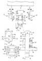
- Fig. 1 of the drawings generally include a pair of bracket means 10, 10' connected by arms 12, 12' to a moveable robot "hand" 14 forming part of a robotic machine conventionally having driven supporting structure (not shown) by which hand 14 is supported and moved as desired in differing directions.
- Arms 12, 12' mount brackets 10, 10' for movement in unison with the hand and for movement relative to it in the direction of the double-headed arrows under the impetus of suitable drive means (not shown) associated with the hand and with the upper ends of arms 12, 12'.
- suitable drive means not shown
- 1 apparatus further includes a tool holder 16 fixedly mounted in any suitable manner upon a base 18 and supporting a pair of tool elements 20, 20' that are connectable at desired times to brackets 10, 10' for use in the performance of a task by the robot of which hand 14 forms a part.
- a tool holder 16 fixedly mounted in any suitable manner upon a base 18 and supporting a pair of tool elements 20, 20' that are connectable at desired times to brackets 10, 10' for use in the performance of a task by the robot of which hand 14 forms a part.
- the illustrated tools 20, 20' are simple rectangularly-shaped "finger" elements such as might be used to cooperatively grasp or clamp an object (not shown) located therebetween.
- a bore 22 extends through the upper shank portion of tool 20.
- Upper and lower pairs of aligned stud element 24 and 26 project outwardly from opposite sides of the shank portion of tool 20 in vertically spaced parallel relationship to each other.
- Bore 22 comprises part of engageable and disengageable connecting means by which tool 20 is releasably connected to holder 16.
- the aforesaid connecting means further includes a cylindrical pin element 28 projecting horizontally outwardly from one side of the upper portion of holder 16, and a pair of spring-loaded ball-type detents 30 projecting from one side of a slot 32 extending vertically through the lower portion of holder 16.
- holder pin 28 projects into bore 22 and the outer surfaces of the pin and of tool 20 are substantially coplanar.
- Tool 20 is received by holder slot 32 and projects vertically beyond it.
- Detents 30 engage the adjacent side face of tool 20 and bias the opposite side of the tool into engagement with the opposite side of holder slot 32.
- the outer edge 34 of the aforesaid opposite side of holder slot 32 preferably and illustratively is beveled, as shown in Fig. 3, to facilitate introduction of tool 20 within slot 32.
- the biasing force of detents 30 is sufficient to prevent inadvertent disengagement of tool 20 from holder 16 by vibration and the like, while allowing positive removal of the tool from the open side of holder slot 32, in a manner subsequently decribed when desired.
- Tool 20' is identical to tool 20, and is mounted in the same manner upon the opposite side of holder 16 by holder components identical to those associated with tool 20.
- Bore 22 of tool 20 also comprises part of engageable and disengageable connecting means for releasably connecting the tool at desired times to bracket 10 of robot hand 14.
- Such connecting means additionally includes upper and lower pairs of aligned arm elements 36 and 38 that project horizontally outwardly from side face 40 of bracket 10 and have undersurface grooves or openings 42 adapted to captively receive stud elements 24, 26 of tool 20.
- the aforesaid connecting means further includes a pin element 44 slidably mounted within a bore 46 extending horizontally through bracket 10 and opening from face 40 thereof.
- a spring 48 within bore 46 biases pin 44 to the right, as viewed in Figs.
- bracket 10' may be and illustratively is identical to that of bracket 10.
- bracket 10 transfer of tool 20 from holder 16 to bracket 10 is initiated by movement of the bracket to a position such as illustrated in Fig. 5 and wherein bracket face 40 is in overlying engagement with the left surface of tool 20, and bracket arms 36, 38 respectively overlie stud elements 24, 26 of tool 20.
- Movement of bracket 10 to its aforesaid illustrated position may be effected by vertical movement of hand 14 (Fig. 1) and by horizontal movement of the hand and/or of the arm 12 supporting bracket 10 for movement relative to hand 14. In any event, during horizontal movement of bracket 10 to its Fig. 5 position, engagement between pin element 44 and the surface of tool 20 occurs.
- bracket 10 begins axial movement of the pin element from its Fig. 1 extended position to a retracted position such as shown in Fig. 5 and wherein the tapered outer end of the pin element does not project significantly beyond bracket face 40.
- Bracket 10 next is moved vertically downwardly, by vertical movement of robot hand 14 (Fig. 1), to a position such as illustrated in Fig. 6. This causes stud elements 24 and 26 upon tool 20 to be captively received within undersurface openings 40, 42 of bracket arms 36 and 38, respectively.
- the vertical movement of bracket 10 also axially aligns pin element 44 of bracket 10 and tool bore 22. However, pin 44 is prevented from entering bore 22 by its abutment with the outer end of the holder pin 28 then still with the bore.
- bracket 10 next undergoes outward horizontal movement away from tool holder 16.
- tool 20 slides outwardly along holder pin 28 due to the engagement of bracket arms 36, 38 with the tool stud elements 24, 26.
- This allows the tapered outer end portion of spring-biased bracket pin 44 to pass into the chamferred outer end portion of tool bore 22.
- the biasing force exerted by spring 48 (Fig. 5) upon pin 44 then causes the latter to maintain engagement between tool studs 24, 26 and bracket arms 36, 38.
- Tool 20 thus remains connected to bracket 10 following the tool's complete disengagement from pin 28 and detents 30 (Fig. 3) of holder 16.
- tool 20 The slightly undersize/oversize relationship between tool studs 24, 26 and the undersurface openings of bracket arms 36, 38 causes tool 20 to normally be biased by spring 48 (Fig. 5) to a forwardly (rightwardly, as viewed in the drawings) position shown in Fig. 7 and wherein the tool is spaced forwardly from bracket face 40.
- Tool 20 therefore is capable of limited translatory rearward (leftward) movement relative to bracket 10, and also of limited pivotal movement in a clockwise (as viewed in Fig. 7) direction about the axis of upper tool studs 24.
- the aforesaid movements of tool 20 are resiliently opposed by the biasing force of spring 48, which force may be varied by rotation of set screw 50 (Fig. 5).
- the maximum extent of the aforesaid movements of tool 20 may be varied by changing the extent of the projection of set screw 52 (Figs. 2 and 5) beyond bracket face 40.
- the tool's capability for restricted rearward movements may if desired be advantageously employed to limit the force initially imposed by the tool on an engaged object (not shown) clamped between tools 20, 20'.
- a suitable motion sensor such as the limit switch 56 shown by phantom lines in Fig. 7, the rearward movement of tool 20 may also be utilized to detect the tool's engagement with and/or disengagement from an object.
- the tool Upon completion of use of tool 20 by the robot, the tool is returned from the bracket 20 to holder 16 by causing the bracket to undergo in reverse sequence the movements described above and illustrated in Figs. 5-7.
- tools 20, 20' may be simultaneously transferred between brackets 10, 10' and tool holder 16.
Landscapes
- Engineering & Computer Science (AREA)
- Mechanical Engineering (AREA)
- Robotics (AREA)
- Manipulator (AREA)
- Automatic Assembly (AREA)
Applications Claiming Priority (2)
| Application Number | Priority Date | Filing Date | Title |
|---|---|---|---|
| US802893 | 1985-11-29 | ||
| US06/802,893 US4660274A (en) | 1985-11-29 | 1985-11-29 | Robot tool changing apparatus |
Publications (2)
| Publication Number | Publication Date |
|---|---|
| EP0227231A1 true EP0227231A1 (fr) | 1987-07-01 |
| EP0227231B1 EP0227231B1 (fr) | 1989-08-30 |
Family
ID=25185012
Family Applications (1)
| Application Number | Title | Priority Date | Filing Date |
|---|---|---|---|
| EP86307956A Expired EP0227231B1 (fr) | 1985-11-29 | 1986-10-15 | Changeur d'outils pour robots |
Country Status (5)
| Country | Link |
|---|---|
| US (1) | US4660274A (fr) |
| EP (1) | EP0227231B1 (fr) |
| JP (1) | JPS62130189A (fr) |
| CA (1) | CA1252490A (fr) |
| DE (1) | DE3665276D1 (fr) |
Cited By (1)
| Publication number | Priority date | Publication date | Assignee | Title |
|---|---|---|---|---|
| US7207611B2 (en) | 2003-10-09 | 2007-04-24 | Deckel Maho Pfronten Gmbh | Tool handling device |
Families Citing this family (35)
| Publication number | Priority date | Publication date | Assignee | Title |
|---|---|---|---|---|
| US5938258A (en) * | 1986-02-15 | 1999-08-17 | Master Appliance Corp. | Power actuated tweezer |
| US4784421A (en) * | 1986-04-18 | 1988-11-15 | Mecanotron Corporation | Interchangeable tool mounting mechanism for robots |
| US4852242A (en) * | 1988-03-24 | 1989-08-01 | Hewlett-Packard Company | Tool coupling apparatus and method |
| US4883939A (en) * | 1988-06-21 | 1989-11-28 | Automatic Tool Control And Management Systems, Inc. | Automatic tool changer for workpiece processing machines |
| US4941577A (en) * | 1988-07-21 | 1990-07-17 | Space Industries Partnership, L.P. | Portable robotic tool rack |
| US4996753A (en) * | 1988-09-30 | 1991-03-05 | The Boeing Company | Robot end effector exchange system |
| FR2652530A1 (fr) * | 1989-10-04 | 1991-04-05 | Snecma | Tete de fraisage, notamment pour robot d'usinage. |
| US5201617A (en) * | 1989-10-04 | 1993-04-13 | Societe Nationale D'etude Et De Construction De Moteurs D'aviation S.N.E.C.M.A. | Apparatus for supporting a machine tool on a robot arm |
| US5256128A (en) * | 1990-01-17 | 1993-10-26 | Hewlett-Packard Company | Gripper exchange mechanism for small robots |
| US4993139A (en) * | 1990-04-02 | 1991-02-19 | The United States Of America As Represented By The United States Department Of Energy | System for exchanging tools and end effectors on a robot |
| US5044063A (en) * | 1990-11-02 | 1991-09-03 | The United States Of America As Represented By The Administrator Of The National Aeronautics And Space Administration | Robotic tool change mechanism |
| JPH0532004A (ja) * | 1991-06-07 | 1993-02-09 | Tokyo Electric Co Ltd | レジスタ用プリンタ |
| US6019409A (en) * | 1997-09-23 | 2000-02-01 | Phd, Inc. | Adjustable positioning target assembly |
| US5947880A (en) * | 1998-04-29 | 1999-09-07 | Eastman Kodak Company | Self-aligning tool holder for use with robotic arms |
| CH698240B1 (de) * | 1998-11-17 | 2009-06-30 | Tecan Trading Ag | Verfahren zum Wägen von Proberöhren, Zuführeinrichtung sowie Arbeitsstation. |
| US6073512A (en) * | 1998-12-14 | 2000-06-13 | Delaware Capital Formation, Inc. | Manual quick change tool changer |
| FR2819210B1 (fr) * | 2001-01-11 | 2003-03-28 | Japp Inventeurs | Machine automatique a poser des pointes flexibles sur un cadre |
| US6569070B1 (en) * | 2002-01-09 | 2003-05-27 | Dallas Design And Technology, Inc. | System for changing the tooling carried by a robot |
| US6870481B2 (en) * | 2002-06-03 | 2005-03-22 | Syron Engineering & Manufacturing, L.L.C. | System and method for monitoring connections in a rail assembly |
| CN100436046C (zh) * | 2006-02-11 | 2008-11-26 | 鸿富锦精密工业(深圳)有限公司 | 夹具更换装置 |
| US8500132B2 (en) * | 2006-04-04 | 2013-08-06 | Ati Industrial Automation, Inc. | Rotating coupling for robotic tool changer with one-way clutch and dual-button handle mechanism |
| US20080182738A1 (en) * | 2007-01-31 | 2008-07-31 | Terry Grunke | Robotic end-of-arm tool quick-change device |
| GB0717969D0 (en) * | 2007-09-14 | 2007-10-24 | Renishaw Plc | Module changing for modular probe |
| US8056949B1 (en) * | 2008-09-11 | 2011-11-15 | The United States Of America As Represented By The Secretary Of The Navy | Universal gripper block for a robotic arm |
| US20140007731A1 (en) | 2012-07-06 | 2014-01-09 | Persimmon Technologies Corporation | High capacity robot arm |
| JP6195333B2 (ja) * | 2012-08-08 | 2017-09-13 | キヤノン株式会社 | ロボット装置 |
| US9207657B2 (en) | 2012-09-28 | 2015-12-08 | Clover Technologies Group, Llc | Manufacturing system with interchangeable tooling heads and tooling nests |
| JP6502956B2 (ja) | 2014-03-17 | 2019-04-17 | エフアンドピー ロボテックス アクチェンゲゼルシャフト | ロボット・システム用グリッパ・フィンガのグリッパ・チップを置き換えるためのアセンブリ・デバイス |
| EP3119564A1 (fr) | 2014-03-17 | 2017-01-25 | F&P Robotics AG | Doigt de préhension, pointe de préhension et mâchoire de préhension, ainsi que système robotique |
| US10384357B2 (en) * | 2015-09-08 | 2019-08-20 | The Johns Hopkins University | Rigid temporary attachment device for a robotic gripper |
| DE102016004087A1 (de) * | 2016-02-15 | 2017-08-17 | Kastanienbaum GmbH | Effektoreinheit für einen Roboter, Arbeitsvorrichtung mit einem Roboter und Verfahren zum Wechseln eines Effektors bei Robotern |
| JP6502878B2 (ja) * | 2016-03-01 | 2019-04-17 | 株式会社スギノマシン | ハンドストッカおよびハンド |
| DE102016107167A1 (de) * | 2016-04-18 | 2017-10-19 | Krones Ag | Verschließerkopf zum Verschließen eines Behälters mit einem Behälterverschluss |
| DE102023109305A1 (de) | 2023-04-13 | 2024-10-17 | Goldfuß engineering GmbH | Kopplungssystem und Magazinanordnung |
| DE102023001583A1 (de) * | 2023-04-21 | 2024-10-24 | HYDAC PTK Produktionstechnik GmbH | Haltevorrichtung |
Citations (4)
| Publication number | Priority date | Publication date | Assignee | Title |
|---|---|---|---|---|
| GB2130550A (en) * | 1982-11-27 | 1984-06-06 | Cleveland Guest | Robot hand |
| EP0151819A2 (fr) * | 1984-02-13 | 1985-08-21 | BISIACH & CARRU' S.p.A. | Mécanisme automatique pour changement d'outils pour les robots industriels |
| DD226826A1 (de) * | 1984-09-07 | 1985-09-04 | Smab Forsch Entw Rat | Auswechselbare greiferfinger |
| EP0155362A1 (fr) * | 1984-03-16 | 1985-09-25 | International Business Machines Corporation | Appareil de changement d'outil pour pince de manipulateur |
Family Cites Families (8)
| Publication number | Priority date | Publication date | Assignee | Title |
|---|---|---|---|---|
| US4141133A (en) * | 1975-09-02 | 1979-02-27 | The Bullard Company | Tool changer for vertical boring machine |
| US4281447A (en) * | 1979-03-01 | 1981-08-04 | Mcdonnell Douglas Corporation | Detachable tool interface system for a robot |
| US4486928A (en) * | 1981-07-09 | 1984-12-11 | Magnavox Government And Industrial Electronics Company | Apparatus for tool storage and selection |
| US4510684A (en) * | 1981-12-08 | 1985-04-16 | Zymark Corporation | Robot tool system |
| JPS58137592A (ja) * | 1982-02-08 | 1983-08-16 | トヨタ自動車株式会社 | 工具交換装置付き産業用ロボツトおよびそのロボツトを用いた溶接方法 |
| US4543032A (en) * | 1983-03-02 | 1985-09-24 | International Business Machines Corporation | Robot manipulator with automatically changeable finger tools |
| US4520550A (en) * | 1983-05-27 | 1985-06-04 | Automated Robotic Systems, Inc. | Robot tool changer |
| US4512709A (en) * | 1983-07-25 | 1985-04-23 | Cincinnati Milacron Inc. | Robot toolchanger system |
-
1985
- 1985-11-29 US US06/802,893 patent/US4660274A/en not_active Expired - Fee Related
-
1986
- 1986-10-15 EP EP86307956A patent/EP0227231B1/fr not_active Expired
- 1986-10-15 DE DE8686307956T patent/DE3665276D1/de not_active Expired
- 1986-11-18 CA CA000523253A patent/CA1252490A/fr not_active Expired
- 1986-11-28 JP JP61282241A patent/JPS62130189A/ja active Pending
Patent Citations (4)
| Publication number | Priority date | Publication date | Assignee | Title |
|---|---|---|---|---|
| GB2130550A (en) * | 1982-11-27 | 1984-06-06 | Cleveland Guest | Robot hand |
| EP0151819A2 (fr) * | 1984-02-13 | 1985-08-21 | BISIACH & CARRU' S.p.A. | Mécanisme automatique pour changement d'outils pour les robots industriels |
| EP0155362A1 (fr) * | 1984-03-16 | 1985-09-25 | International Business Machines Corporation | Appareil de changement d'outil pour pince de manipulateur |
| DD226826A1 (de) * | 1984-09-07 | 1985-09-04 | Smab Forsch Entw Rat | Auswechselbare greiferfinger |
Cited By (1)
| Publication number | Priority date | Publication date | Assignee | Title |
|---|---|---|---|---|
| US7207611B2 (en) | 2003-10-09 | 2007-04-24 | Deckel Maho Pfronten Gmbh | Tool handling device |
Also Published As
| Publication number | Publication date |
|---|---|
| DE3665276D1 (en) | 1989-10-05 |
| EP0227231B1 (fr) | 1989-08-30 |
| CA1252490A (fr) | 1989-04-11 |
| US4660274A (en) | 1987-04-28 |
| JPS62130189A (ja) | 1987-06-12 |
Similar Documents
| Publication | Publication Date | Title |
|---|---|---|
| EP0227231A1 (fr) | Changeur d'outils pour robots | |
| EP0234677B1 (fr) | Dispositif de serrage | |
| US4299529A (en) | Automated device | |
| US4518307A (en) | Compliant robot arm adapter assembly | |
| US4647028A (en) | Versatile clamping assembly for workbench or the like | |
| US6105949A (en) | Workpiece indexing and clamping system | |
| US4543032A (en) | Robot manipulator with automatically changeable finger tools | |
| US6099058A (en) | Gripping device | |
| US8172234B2 (en) | Collet tool holder having adjustable axis | |
| US5718422A (en) | Workpiece clamping system | |
| EP0163065A1 (fr) | Manipulateur robotisé autopivotant | |
| WO1996020810A1 (fr) | Ensemble de positionnement reglable d'une piece a usiner | |
| US5653038A (en) | Versatile workpiece holding system utilizing connectors selectively positional on work table | |
| US5497980A (en) | Assembly for use in precision machining | |
| US4941577A (en) | Portable robotic tool rack | |
| JPH05285766A (ja) | 工作機械の自動工具交換装置 | |
| US4736934A (en) | Double-acting vise | |
| EP0479740B1 (fr) | Dispositif pour suspendre un robot à une poutre de support | |
| US5816986A (en) | Universal chuck and automated machining system | |
| US4919574A (en) | Tool holder retention system | |
| KR200320307Y1 (ko) | 공작물의 고정장치 | |
| US5358228A (en) | Vise having an invertible V-block | |
| CA1261899A (fr) | Pince de manipulateur | |
| JPH06190616A (ja) | ターニングセンタの爪交換装置とロボットハンド | |
| CN223199041U (zh) | 搬运机器人的自适应抓取装置 |
Legal Events
| Date | Code | Title | Description |
|---|---|---|---|
| PUAI | Public reference made under article 153(3) epc to a published international application that has entered the european phase |
Free format text: ORIGINAL CODE: 0009012 |
|
| AK | Designated contracting states |
Kind code of ref document: A1 Designated state(s): DE GB IT SE |
|
| 17P | Request for examination filed |
Effective date: 19870617 |
|
| 17Q | First examination report despatched |
Effective date: 19880510 |
|
| GRAA | (expected) grant |
Free format text: ORIGINAL CODE: 0009210 |
|
| AK | Designated contracting states |
Kind code of ref document: B1 Designated state(s): DE GB IT SE |
|
| PG25 | Lapsed in a contracting state [announced via postgrant information from national office to epo] |
Ref country code: IT Free format text: LAPSE BECAUSE OF FAILURE TO SUBMIT A TRANSLATION OF THE DESCRIPTION OR TO PAY THE FEE WITHIN THE PRESCRIBED TIME-LIMIT;WARNING: LAPSES OF ITALIAN PATENTS WITH EFFECTIVE DATE BEFORE 2007 MAY HAVE OCCURRED AT ANY TIME BEFORE 2007. THE CORRECT EFFECTIVE DATE MAY BE DIFFERENT FROM THE ONE RECORDED. Effective date: 19890830 Ref country code: SE Effective date: 19890830 |
|
| REF | Corresponds to: |
Ref document number: 3665276 Country of ref document: DE Date of ref document: 19891005 |
|
| PLBE | No opposition filed within time limit |
Free format text: ORIGINAL CODE: 0009261 |
|
| STAA | Information on the status of an ep patent application or granted ep patent |
Free format text: STATUS: NO OPPOSITION FILED WITHIN TIME LIMIT |
|
| PG25 | Lapsed in a contracting state [announced via postgrant information from national office to epo] |
Ref country code: DE Effective date: 19900703 |
|
| 26N | No opposition filed | ||
| PG25 | Lapsed in a contracting state [announced via postgrant information from national office to epo] |
Ref country code: GB Effective date: 19901015 |
|
| GBPC | Gb: european patent ceased through non-payment of renewal fee |