EP0227333A2 - Appareil de détection de direction de rotation - Google Patents
Appareil de détection de direction de rotation Download PDFInfo
- Publication number
- EP0227333A2 EP0227333A2 EP86309343A EP86309343A EP0227333A2 EP 0227333 A2 EP0227333 A2 EP 0227333A2 EP 86309343 A EP86309343 A EP 86309343A EP 86309343 A EP86309343 A EP 86309343A EP 0227333 A2 EP0227333 A2 EP 0227333A2
- Authority
- EP
- European Patent Office
- Prior art keywords
- signals
- detectors
- rotation
- voltage
- detector
- Prior art date
- Legal status (The legal status is an assumption and is not a legal conclusion. Google has not performed a legal analysis and makes no representation as to the accuracy of the status listed.)
- Granted
Links
Images



Classifications
-
- H—ELECTRICITY
- H03—ELECTRONIC CIRCUITRY
- H03M—CODING; DECODING; CODE CONVERSION IN GENERAL
- H03M1/00—Analogue/digital conversion; Digital/analogue conversion
- H03M1/12—Analogue/digital converters
- H03M1/22—Analogue/digital converters pattern-reading type
- H03M1/24—Analogue/digital converters pattern-reading type using relatively movable reader and disc or strip
- H03M1/28—Analogue/digital converters pattern-reading type using relatively movable reader and disc or strip with non-weighted coding
- H03M1/30—Analogue/digital converters pattern-reading type using relatively movable reader and disc or strip with non-weighted coding incremental
- H03M1/303—Circuits or methods for processing the quadrature signals
- H03M1/305—Circuits or methods for processing the quadrature signals for detecting the direction of movement
Definitions
- This invention relates to apparatus for sensing direction of rotation, in particular of rotation of a shaft of a permanent magnet electric motor, which may be a brushless motor.
- an apparatus for sensing the direction of rotation of a device comprising a rotor for rotation with said device, first and second detectors mounted on a relatively fixed part of said apparatus, at least one pair of magnets mounted on said rotor so as respectively to present opposite magnetic poles to said first detector, said first detector device being responsive to the flux from said magnets for providing a first voltage signal whose polarity is dependent on the polarity and direction of rotation of an adjacent one of said magnetic poles, and said second detector providing a second voltage signal substantially coincident with one polarity of said first signal, means for comparing the voltage signals from said first and second detectors and means for providing first or second indicating signals dependent on correspondence or otherwise of said voltage signals.
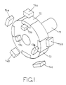
- a rotor 10 is mounted on a shaft 11 which in the present example is the shaft of a brushless d.c. motor.
- a shaft 11 which in the present example is the shaft of a brushless d.c. motor.
- four equi-angularly spaced permanent magnets 12 which are arranged so that effective poles of adjacent magnets are dissimilar.
- Mounted on a relatively fixed part (not shown) of the apparatus are three Hall sensors 13a-13c which are spaced 120° apart and located relative to the rotor 10 so as to respectively generate positive-going rectangular wave signals A, C, B on correspondingly designated lines ( Figure 2) in response to the presence of a north pole only.
- each of the sensors 13, 14 reacts with the magnets 12 to provide positive-going output signals of 90° duration.
- Figure 2 shows more clearly the relative angular positions of the sensors 13, 14. It is to be understood that Figures 1 and 2 are diagrammatic only, the relative radial positions of the sensors being distorted somewhat for clarity.
- the sensors 13 include, as is well known in the art, pulse-shaping circuits and, as shown in Figure 6, for clockwise rotation provide rectangular wave output signals in the sequence A, B, C.
- the sensors 14 provide sinusoidal outputs whose positive-going zero crossing points occur in the sequence D, G, E, H, F.
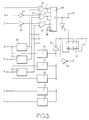
- the signal A is applied to one input of an exclusive OR gate 20 and the signals B, C are applied to one input of respective exclusive OR gates 21, 22 by way of respective inverters 23, 24.
- the signals D, G, F are applied to respective identical pulse shaping circuits 25, one of which is shown in Figure 4 and includes a comparator 26 and a resistor network 27.
- the resulting rectangular output signals D1, G1, F1 are applied to the second inputs of the respective gates 20, 21, 22.
- the time relationships of the signals A, B, C, E, H, D1, G1, F1 are shown in Figure 6 as are the output signals J, K, L from the respective gates 20, 21, 22.
- direction of rotation is indicated by the exclusive OR (or inequality) gate 20, which is arranged to provide a low level signal in the presence of equality, indicating clockwise rotation.
- Inversion of the signals B and C has the effect that the gates 21, 22 respectively provide low level signals in the presence of inequality between signals B and G1 and between signals C and F1.
- Selection of the appropriate two of the signals E to H is made on the basis that the one of the signals E to H which is most nearly opposite in phase with the signal B or C is compared with the latter, and also on the basis that the positive-going parts of the signals K and L, and their associated zones of uncertainty, do not overlap in time with each other or with the uncertainty zones of signal J.
- Selection of signals for comparison is extended by the fact that it is only the relative time relationships of the zero crossing points of the signals A-H which need to be taken into account since positive-going signals may be compared with negative-going signals if an inversion of one of these signals is made before comparison.
- the signals K and L are also low level signals having positive-going pulses at 90° intervals of rotation of the rotor 10, these positive-going pulses also being accompanied by zones of uncertainty.
- the signals J, K, L are applied to a majority logic gate 28 of a type commercially available under the designation 4530 which provide a high level output signal if three or more of its input signals are at a low level.
- the output signal from the gate 28 is detectable at a terminal 29, a low level signal indicating clockwise rotation of the rotor 10, as viewed in Figures 1 and 2.
- the output signal from the gate 28 is applied to a control terminal of a semi-conductor switch device 30 of a type commercially available under the designation HI 200.
- the output of the gate 28 is also applied through an inverter 31 to a further control terminal of the switch device 30.
- Input signals D-H are applied to respective ones of identical precision half-wave rectifier circuits 32 one of which is shown in Figure 5.
- the circuit of Figure 5 overcomes inaccuracies which arise from the direct rectification of small a.c. signals as a result of non-linearity of the forward characteristics of diodes.
- the half-wave rectified outputs are summed by an amplifier 33, the phase difference between them resulting in a substantially constant d.c. level whose magnitude is proportional to the speed of the rotor 10.
- This d.c. level is applied to an input 5 of the switch device 30 which is responsive to a low level signal at the terminal 29 to connect the input 5 to an output terminal 34.
- the d.c. level at 33 is also applied through an inverter 35 to a further input 10 of the switch device 30 which is connected to the output terminal 34 by a low level signal from the inverter 31.
- a low level signal at the terminal 29 indicates clockwise rotation of the rotor 10 and this signal also applies the d.c. level at 33 to the terminal 34.
- a high level signal at terminal 29 is converted to a low level by the inverter 31 and causes the inverted level at 33 to be applied to the terminal 34.
- the signal at the terminal 34 thus provides, by its magnitude and polarity, an indication of the speed and direction of rotation of the rotor 10.
- the gate 28 by its response to correspondence between any two of the signals J, K, L has the effect that the pulses and/or zones of ambiguity therein do not affect the output signal from the gate 28 since these pulses and zones do not coincide in time.
- the rotor 10 may comprise, or form part of, the rotor of a brushless d.c. motor, in which case the Hall sensors 13 may also be those used for timing the commutation of the motor.
- phase outputs D, F and G out of a total of five such phase outputs, are compared with the respective outputs of the sensors 13, so that two out of three of the compared results J, K, L will always correspond, it will be understood that for other total numbers of phase outputs other number of comparisons are possible such that the majority logic gate 28 always provides an uninterrupted output signal.
- the sensors 13a, 14a need not be angularly aligned about the axis of the rotor 10, as shown in Figure 1, nor be responsive to the same one of the magnets 12 on each occasion. It is necessary only that the sensor 13a shall provide an output signal A which is substantially coincident with one polarity of the alternating output signal from the sensor 14a, to enable the signals A and D1 to be compared. In such an embodiment the sensors 13a, 14a may be mutually angularly and axially spaced, and be responsive to separate magnets on different parts of a rotor, without affecting the relationship of the signals A, D1 and J shown in Figure 6.
- the sensors 13a, 13b, 13c comprise the stator windings of a three phase rotary electric machine, the rotor 10 being secured to the rotor of the machine for rotation therewith.
Landscapes
- Engineering & Computer Science (AREA)
- Signal Processing (AREA)
- Theoretical Computer Science (AREA)
- Indicating Or Recording The Presence, Absence, Or Direction Of Movement (AREA)
- Control Of Motors That Do Not Use Commutators (AREA)
Applications Claiming Priority (2)
| Application Number | Priority Date | Filing Date | Title |
|---|---|---|---|
| GB858531235A GB8531235D0 (en) | 1985-12-19 | 1985-12-19 | Sensing direction of rotation |
| GB8531235 | 1985-12-19 |
Publications (3)
| Publication Number | Publication Date |
|---|---|
| EP0227333A2 true EP0227333A2 (fr) | 1987-07-01 |
| EP0227333A3 EP0227333A3 (en) | 1988-11-02 |
| EP0227333B1 EP0227333B1 (fr) | 1991-04-17 |
Family
ID=10589978
Family Applications (1)
| Application Number | Title | Priority Date | Filing Date |
|---|---|---|---|
| EP86309343A Expired - Lifetime EP0227333B1 (fr) | 1985-12-19 | 1986-12-01 | Appareil de détection de direction de rotation |
Country Status (5)
| Country | Link |
|---|---|
| US (1) | US4758769A (fr) |
| EP (1) | EP0227333B1 (fr) |
| JP (1) | JPH0648275B2 (fr) |
| DE (1) | DE3678807D1 (fr) |
| GB (1) | GB8531235D0 (fr) |
Cited By (2)
| Publication number | Priority date | Publication date | Assignee | Title |
|---|---|---|---|---|
| DE19820014A1 (de) * | 1998-05-06 | 1999-11-11 | Heidenhain Gmbh Dr Johannes | Multiturn-Codedrehgeber |
| CN111799954A (zh) * | 2019-04-04 | 2020-10-20 | 日本电产株式会社 | 电动机 |
Families Citing this family (7)
| Publication number | Priority date | Publication date | Assignee | Title |
|---|---|---|---|---|
| US4851752A (en) * | 1987-03-26 | 1989-07-25 | Yamaha Corporation | Magnetic encoder and a method for producing the same |
| DE4113201A1 (de) * | 1991-04-23 | 1992-10-29 | Oplaender Wilo Werk Gmbh | Verfahren zur beruehrungslosen kontrolle der drehrichtung elektrischer maschinen |
| KR100296393B1 (ko) * | 1997-04-07 | 2001-10-24 | 이상윤 | 무단변속교류모터 |
| SG71047A1 (en) * | 1997-09-27 | 2000-03-21 | Majeel Lab Pte Ltd | Amplifier circuit employing floating error cancellation |
| KR100604894B1 (ko) * | 2004-08-21 | 2006-07-28 | 삼성전자주식회사 | 반도체 제조설비의 회전운동장치 |
| US7893570B2 (en) * | 2007-06-14 | 2011-02-22 | Richard Redinbo | Clean engine |
| US10821591B2 (en) | 2012-11-13 | 2020-11-03 | Milwaukee Electric Tool Corporation | High-power cordless, hand-held power tool including a brushless direct current motor |
Family Cites Families (6)
| Publication number | Priority date | Publication date | Assignee | Title |
|---|---|---|---|---|
| US3678358A (en) * | 1970-07-14 | 1972-07-18 | Gen Electric | Brushless dc adjustable speed drive with static regenerative dc motor control |
| US4072881A (en) * | 1975-11-06 | 1978-02-07 | Itsuki Ban | Axial-air-gap type semiconductor electric motor |
| JPS6035911B2 (ja) * | 1978-02-01 | 1985-08-17 | ソニー株式会社 | 回転体の回転制御装置 |
| DE2817169C2 (de) * | 1978-04-20 | 1986-10-23 | Robert Bosch Gmbh, 7000 Stuttgart | Einrichtung zur Abgabe von Impulsen |
| GB2050627B (en) * | 1979-05-16 | 1983-09-21 | Ransome Hoffmann Pollard | Mechanical assemblies employing sensing means for sensing motion or position |
| DE3112709C2 (de) * | 1981-03-31 | 1986-11-27 | Doduco KG Dr. Eugen Dürrwächter, 7530 Pforzheim | Induktiver Drehgeber |
-
1985
- 1985-12-19 GB GB858531235A patent/GB8531235D0/en active Pending
-
1986
- 1986-12-01 EP EP86309343A patent/EP0227333B1/fr not_active Expired - Lifetime
- 1986-12-01 DE DE8686309343T patent/DE3678807D1/de not_active Expired - Lifetime
- 1986-12-02 US US06/936,793 patent/US4758769A/en not_active Expired - Fee Related
- 1986-12-19 JP JP61301841A patent/JPH0648275B2/ja not_active Expired - Lifetime
Cited By (3)
| Publication number | Priority date | Publication date | Assignee | Title |
|---|---|---|---|---|
| DE19820014A1 (de) * | 1998-05-06 | 1999-11-11 | Heidenhain Gmbh Dr Johannes | Multiturn-Codedrehgeber |
| US6542088B1 (en) | 1998-05-06 | 2003-04-01 | Dr. Johannes Heidenheim Gmbh | Multiturn rotary encoder with multiple code carriers coupled by a reduction gear |
| CN111799954A (zh) * | 2019-04-04 | 2020-10-20 | 日本电产株式会社 | 电动机 |
Also Published As
| Publication number | Publication date |
|---|---|
| US4758769A (en) | 1988-07-19 |
| DE3678807D1 (de) | 1991-05-23 |
| JPS62184362A (ja) | 1987-08-12 |
| EP0227333B1 (fr) | 1991-04-17 |
| JPH0648275B2 (ja) | 1994-06-22 |
| GB8531235D0 (en) | 1986-01-29 |
| EP0227333A3 (en) | 1988-11-02 |
Similar Documents
| Publication | Publication Date | Title |
|---|---|---|
| EP0316077B1 (fr) | Moteur sans balais | |
| US4758769A (en) | Apparatus for sensing direction of rotation | |
| US20080143323A1 (en) | Method of detecting rotational position by using hall element and hall element resolver | |
| US4495464A (en) | Non-contacting, speed-detecting device of a direct-current generator type | |
| US3614616A (en) | Bidirectional ac tachometer | |
| US6906494B2 (en) | Motor controller | |
| JP4375638B2 (ja) | モータ回転軸の絶対位置検出方法 | |
| KR20110016573A (ko) | 회전자 위치 센서 | |
| US8892395B2 (en) | Detecting angular position of a rotating device | |
| USH939H (en) | Commutator pulse tachometer | |
| US3439243A (en) | Brushless torquer | |
| JPH0342325Y2 (fr) | ||
| KR910000100B1 (ko) | 회전수 제어방법 | |
| JPH0125287Y2 (fr) | ||
| KR100203505B1 (ko) | 제트 펄스를 이용한 자극위치 보정방법 | |
| SU790006A1 (ru) | Устройство дл определени количества оборотов и направлени вращени ротора сельсина | |
| JPS6235356B2 (fr) | ||
| JP2772440B2 (ja) | ブラシレスモータ | |
| JPH0311987A (ja) | 電動機の回転位置検出方法 | |
| JPH02284067A (ja) | モータの回転速度検出回路 | |
| JPS60320A (ja) | Acサ−ボモ−タ用エンコ−ダ | |
| JPS6235354B2 (fr) | ||
| JPH0583869B2 (fr) | ||
| JPS5897619A (ja) | 回転パルス検出装置 | |
| JPS6348178A (ja) | デイジタル式電動機制御方法 |
Legal Events
| Date | Code | Title | Description |
|---|---|---|---|
| PUAI | Public reference made under article 153(3) epc to a published international application that has entered the european phase |
Free format text: ORIGINAL CODE: 0009012 |
|
| AK | Designated contracting states |
Kind code of ref document: A2 Designated state(s): DE FR GB IT |
|
| PUAL | Search report despatched |
Free format text: ORIGINAL CODE: 0009013 |
|
| AK | Designated contracting states |
Kind code of ref document: A3 Designated state(s): DE FR GB IT |
|
| 17P | Request for examination filed |
Effective date: 19890421 |
|
| 17Q | First examination report despatched |
Effective date: 19900403 |
|
| GRAA | (expected) grant |
Free format text: ORIGINAL CODE: 0009210 |
|
| AK | Designated contracting states |
Kind code of ref document: B1 Designated state(s): DE FR GB IT |
|
| REF | Corresponds to: |
Ref document number: 3678807 Country of ref document: DE Date of ref document: 19910523 |
|
| ET | Fr: translation filed | ||
| ITF | It: translation for a ep patent filed | ||
| PLBE | No opposition filed within time limit |
Free format text: ORIGINAL CODE: 0009261 |
|
| STAA | Information on the status of an ep patent application or granted ep patent |
Free format text: STATUS: NO OPPOSITION FILED WITHIN TIME LIMIT |
|
| 26N | No opposition filed | ||
| PGFP | Annual fee paid to national office [announced via postgrant information from national office to epo] |
Ref country code: GB Payment date: 19941122 Year of fee payment: 9 |
|
| PGFP | Annual fee paid to national office [announced via postgrant information from national office to epo] |
Ref country code: DE Payment date: 19941123 Year of fee payment: 9 |
|
| PGFP | Annual fee paid to national office [announced via postgrant information from national office to epo] |
Ref country code: FR Payment date: 19941209 Year of fee payment: 9 |
|
| PG25 | Lapsed in a contracting state [announced via postgrant information from national office to epo] |
Ref country code: GB Effective date: 19951201 |
|
| GBPC | Gb: european patent ceased through non-payment of renewal fee |
Effective date: 19951201 |
|
| PG25 | Lapsed in a contracting state [announced via postgrant information from national office to epo] |
Ref country code: FR Effective date: 19960830 |
|
| PG25 | Lapsed in a contracting state [announced via postgrant information from national office to epo] |
Ref country code: DE Effective date: 19960903 |
|
| REG | Reference to a national code |
Ref country code: FR Ref legal event code: ST |
|
| PG25 | Lapsed in a contracting state [announced via postgrant information from national office to epo] |
Ref country code: IT Free format text: LAPSE BECAUSE OF NON-PAYMENT OF DUE FEES;WARNING: LAPSES OF ITALIAN PATENTS WITH EFFECTIVE DATE BEFORE 2007 MAY HAVE OCCURRED AT ANY TIME BEFORE 2007. THE CORRECT EFFECTIVE DATE MAY BE DIFFERENT FROM THE ONE RECORDED. Effective date: 20051201 |