EP0227525A1 - Récipients composites métalloplastiques assemblés par soudure - Google Patents
Récipients composites métalloplastiques assemblés par soudure Download PDFInfo
- Publication number
- EP0227525A1 EP0227525A1 EP86402579A EP86402579A EP0227525A1 EP 0227525 A1 EP0227525 A1 EP 0227525A1 EP 86402579 A EP86402579 A EP 86402579A EP 86402579 A EP86402579 A EP 86402579A EP 0227525 A1 EP0227525 A1 EP 0227525A1
- Authority
- EP
- European Patent Office
- Prior art keywords
- shells
- flaps
- metal layer
- container
- stainless
- Prior art date
- Legal status (The legal status is an assumption and is not a legal conclusion. Google has not performed a legal analysis and makes no representation as to the accuracy of the status listed.)
- Granted
Links
- 238000003466 welding Methods 0.000 title claims abstract description 14
- 239000002131 composite material Substances 0.000 title claims abstract description 7
- 229910052751 metal Inorganic materials 0.000 claims abstract description 27
- 239000002184 metal Substances 0.000 claims abstract description 27
- 229920005989 resin Polymers 0.000 claims abstract description 10
- 239000011347 resin Substances 0.000 claims abstract description 10
- 229920005992 thermoplastic resin Polymers 0.000 claims abstract description 7
- 229920001187 thermosetting polymer Polymers 0.000 claims abstract description 6
- 239000011324 bead Substances 0.000 claims abstract description 5
- 229910045601 alloy Inorganic materials 0.000 claims abstract description 4
- 239000000956 alloy Substances 0.000 claims abstract description 4
- 230000002093 peripheral effect Effects 0.000 claims abstract description 3
- 238000000576 coating method Methods 0.000 claims description 19
- 239000011248 coating agent Substances 0.000 claims description 15
- PXHVJJICTQNCMI-UHFFFAOYSA-N Nickel Chemical compound [Ni] PXHVJJICTQNCMI-UHFFFAOYSA-N 0.000 claims description 4
- 229920000647 polyepoxide Polymers 0.000 claims description 4
- 239000004952 Polyamide Substances 0.000 claims description 3
- 239000004698 Polyethylene Substances 0.000 claims description 3
- 150000002739 metals Chemical class 0.000 claims description 3
- 229920002647 polyamide Polymers 0.000 claims description 3
- 229920000573 polyethylene Polymers 0.000 claims description 3
- -1 polyethylenes Polymers 0.000 claims description 3
- VYZAMTAEIAYCRO-UHFFFAOYSA-N Chromium Chemical compound [Cr] VYZAMTAEIAYCRO-UHFFFAOYSA-N 0.000 claims description 2
- 239000004593 Epoxy Substances 0.000 claims description 2
- 229910052804 chromium Inorganic materials 0.000 claims description 2
- 239000011651 chromium Substances 0.000 claims description 2
- 229910017052 cobalt Inorganic materials 0.000 claims description 2
- 239000010941 cobalt Substances 0.000 claims description 2
- GUTLYIVDDKVIGB-UHFFFAOYSA-N cobalt atom Chemical compound [Co] GUTLYIVDDKVIGB-UHFFFAOYSA-N 0.000 claims description 2
- 229910052759 nickel Inorganic materials 0.000 claims description 2
- 229920005749 polyurethane resin Polymers 0.000 claims description 2
- 229920000915 polyvinyl chloride Polymers 0.000 claims description 2
- HBMJWWWQQXIZIP-UHFFFAOYSA-N silicon carbide Chemical compound [Si+]#[C-] HBMJWWWQQXIZIP-UHFFFAOYSA-N 0.000 claims description 2
- 229910010271 silicon carbide Inorganic materials 0.000 claims description 2
- 229910000640 Fe alloy Inorganic materials 0.000 claims 1
- 239000004800 polyvinyl chloride Substances 0.000 claims 1
- 229910000679 solder Inorganic materials 0.000 abstract 1
- 239000010410 layer Substances 0.000 description 9
- 238000000034 method Methods 0.000 description 7
- 238000005260 corrosion Methods 0.000 description 4
- 229910001092 metal group alloy Inorganic materials 0.000 description 4
- 229910000831 Steel Inorganic materials 0.000 description 3
- 238000004519 manufacturing process Methods 0.000 description 3
- 238000001465 metallisation Methods 0.000 description 3
- 239000000203 mixture Substances 0.000 description 3
- 239000010959 steel Substances 0.000 description 3
- XEEYBQQBJWHFJM-UHFFFAOYSA-N Iron Chemical compound [Fe] XEEYBQQBJWHFJM-UHFFFAOYSA-N 0.000 description 2
- 239000000470 constituent Substances 0.000 description 2
- 238000000354 decomposition reaction Methods 0.000 description 2
- 239000003822 epoxy resin Substances 0.000 description 2
- LNEPOXFFQSENCJ-UHFFFAOYSA-N haloperidol Chemical compound C1CC(O)(C=2C=CC(Cl)=CC=2)CCN1CCCC(=O)C1=CC=C(F)C=C1 LNEPOXFFQSENCJ-UHFFFAOYSA-N 0.000 description 2
- 238000002844 melting Methods 0.000 description 2
- 230000008018 melting Effects 0.000 description 2
- 229920002635 polyurethane Polymers 0.000 description 2
- 239000004814 polyurethane Substances 0.000 description 2
- 239000000843 powder Substances 0.000 description 2
- 239000010935 stainless steel Substances 0.000 description 2
- 229910001220 stainless steel Inorganic materials 0.000 description 2
- 239000000126 substance Substances 0.000 description 2
- 239000002966 varnish Substances 0.000 description 2
- 239000003905 agrochemical Substances 0.000 description 1
- 239000004568 cement Substances 0.000 description 1
- 239000011247 coating layer Substances 0.000 description 1
- 210000003298 dental enamel Anatomy 0.000 description 1
- 238000000151 deposition Methods 0.000 description 1
- 239000003599 detergent Substances 0.000 description 1
- 238000009503 electrostatic coating Methods 0.000 description 1
- 239000000839 emulsion Substances 0.000 description 1
- 238000005516 engineering process Methods 0.000 description 1
- QFXZANXYUCUTQH-UHFFFAOYSA-N ethynol Chemical group OC#C QFXZANXYUCUTQH-UHFFFAOYSA-N 0.000 description 1
- 239000012530 fluid Substances 0.000 description 1
- 239000002828 fuel tank Substances 0.000 description 1
- 239000011521 glass Substances 0.000 description 1
- 229910052742 iron Inorganic materials 0.000 description 1
- 239000002245 particle Substances 0.000 description 1
- 239000011253 protective coating Substances 0.000 description 1
- 238000002791 soaking Methods 0.000 description 1
- 238000005507 spraying Methods 0.000 description 1
- 239000000725 suspension Substances 0.000 description 1
- 229920001169 thermoplastic Polymers 0.000 description 1
- 239000004416 thermosoftening plastic Substances 0.000 description 1
Images

Classifications
-
- B—PERFORMING OPERATIONS; TRANSPORTING
- B65—CONVEYING; PACKING; STORING; HANDLING THIN OR FILAMENTARY MATERIAL
- B65D—CONTAINERS FOR STORAGE OR TRANSPORT OF ARTICLES OR MATERIALS, e.g. BAGS, BARRELS, BOTTLES, BOXES, CANS, CARTONS, CRATES, DRUMS, JARS, TANKS, HOPPERS, FORWARDING CONTAINERS; ACCESSORIES, CLOSURES, OR FITTINGS THEREFOR; PACKAGING ELEMENTS; PACKAGES
- B65D7/00—Containers having bodies formed by interconnecting or uniting two or more rigid, or substantially rigid, components made wholly or mainly of metal
- B65D7/12—Containers having bodies formed by interconnecting or uniting two or more rigid, or substantially rigid, components made wholly or mainly of metal characterised by wall construction or by connections between walls
- B65D7/34—Containers having bodies formed by interconnecting or uniting two or more rigid, or substantially rigid, components made wholly or mainly of metal characterised by wall construction or by connections between walls with permanent connections between walls
- B65D7/38—Containers having bodies formed by interconnecting or uniting two or more rigid, or substantially rigid, components made wholly or mainly of metal characterised by wall construction or by connections between walls with permanent connections between walls formed by soldering, welding, or otherwise uniting opposed surfaces
-
- B—PERFORMING OPERATIONS; TRANSPORTING
- B23—MACHINE TOOLS; METAL-WORKING NOT OTHERWISE PROVIDED FOR
- B23K—SOLDERING OR UNSOLDERING; WELDING; CLADDING OR PLATING BY SOLDERING OR WELDING; CUTTING BY APPLYING HEAT LOCALLY, e.g. FLAME CUTTING; WORKING BY LASER BEAM
- B23K5/00—Gas flame welding
- B23K5/12—Gas flame welding taking account of the properties of the material to be welded
- B23K5/16—Gas flame welding taking account of the properties of the material to be welded of different metals
-
- Y—GENERAL TAGGING OF NEW TECHNOLOGICAL DEVELOPMENTS; GENERAL TAGGING OF CROSS-SECTIONAL TECHNOLOGIES SPANNING OVER SEVERAL SECTIONS OF THE IPC; TECHNICAL SUBJECTS COVERED BY FORMER USPC CROSS-REFERENCE ART COLLECTIONS [XRACs] AND DIGESTS
- Y10—TECHNICAL SUBJECTS COVERED BY FORMER USPC
- Y10S—TECHNICAL SUBJECTS COVERED BY FORMER USPC CROSS-REFERENCE ART COLLECTIONS [XRACs] AND DIGESTS
- Y10S220/00—Receptacles
- Y10S220/29—Welded seam
-
- Y—GENERAL TAGGING OF NEW TECHNOLOGICAL DEVELOPMENTS; GENERAL TAGGING OF CROSS-SECTIONAL TECHNOLOGIES SPANNING OVER SEVERAL SECTIONS OF THE IPC; TECHNICAL SUBJECTS COVERED BY FORMER USPC CROSS-REFERENCE ART COLLECTIONS [XRACs] AND DIGESTS
- Y10—TECHNICAL SUBJECTS COVERED BY FORMER USPC
- Y10S—TECHNICAL SUBJECTS COVERED BY FORMER USPC CROSS-REFERENCE ART COLLECTIONS [XRACs] AND DIGESTS
- Y10S220/00—Receptacles
- Y10S220/917—Corrosion resistant container
Definitions
- the present invention is in the field of assembly by autogenous welding of containers made up of at least two parts of the type of tanks or reactors used by the chemical, agrochemical, pharmaceutical, etc. industries.
- the fluids transported or treated in these containers are understood in the most general way such as: aqueous, organic solutions, chemical detergents, suspensions or emulsions etc ...
- the containers suitable for this transport or treatment are generally made of steel and usually receive protective coatings such as glass cement, enamels or varnishes baked in the oven such as varnishes based on epoxy resins or polyurethanes etc ... They can also be made of steel stainless steel and are therefore without coating.
- the containers in question are limited in their shape since the thermal susceptibility of the coatings mentioned above prohibits them from being produced in several parts and assembled by autogenous welding of the constituent steel parts. Furthermore, the containers obtained by boilermaking from stainless steel sheets are very expensive.
- the object of the present invention is to remedy these drawbacks and limitations in a simple manner.
- the invention relates firstly to composite metal containers consisting of two shells assembled by welding, characterized in that the two shells can bear one on the other along planar peripheral flaps whose edge is chamfered, these flaps and their chamfered edges being provided with a stainless metal layer extending towards the interior of the finished container up to beyond the connection leave of the flat part and of the container body, which container also carrying an anticorrosion coating made of thermoplastic resins or thermosetting resins, the anticorrosion layer being such that it stops at a distance of at least 15 mm from the area where performed the autogenous welding and that it overlaps the metal layer over a length of at least 10 mm and the autogenous welding being carried out by a bead of stainless alloy of the same kind as the layer deposited on the flaps of the two shells.
- the invention also relates to a technique for manufacturing these containers.
- This technique comprises a first phase which consists in depositing, in particular by schooping, the name by which we mean in technology the application to the oxyacetylene torch of a metal introduced in the form of continuous wire into the torch, on the flat or flat surfaces of the elements of container to be assembled, of a stainless metal alloy consisting of iron and one of the metals of the group chromium, nickel, cobalt.
- the stainless metal alloy is injected into the torch in the form of powder and contains, in addition to the metals mentioned, silicon carbide.
- the thickness of the alloy deposited varies according to the applications from 200 to 600 microns.
- the outer edge of the flaps to be assembled is advantageously chamfered at an angle between 45 and 60 ° relative to the assembly plane.
- an anti-corrosion coating is deposited on the inner wall of the container element to be assembled, which may be made of thermoplastic resins chosen from the group of polyamides, fluorinated resins, polyethylenes, preferably of high molecular weight or PVC.
- This coating can also consist of thermosetting resins chosen from the group of epoxy or polyurethane resins.
- thermoplastic resins are advantageously used from fine powders with a particle size between 10 and 400 microns and by known methods such as electrostatic coating, soaking or spraying. Depending on the case, the thickness of this coating can vary from 200 microns to 5 mm.
- a reserve is observed on the flat part of the elements to be assembled in which the stainless metal alloy deposited during the first phase remains bare.
- the anticorrosion coating applied in the second phase is such that it must always cover the stainless metal deposit so as to ensure the continuity of the protection of the interior of the container obtained.
- the principle of covering the stainless metal coating with the anti-corrosion thermoplastic coating will be respected each time.
- the overlap area (where the two coatings overlap) must not be less than 10 mm.
- a container according to the invention consists of two shells (11) and (12) bearing one on the other by flaps along the joint plane (19). These flaps receive by schooping a metallization based on a stainless composition on all surfaces (13), (14) comprising, in addition to the flap itself, a rounded surface connecting the flap to the interior cavity of the shell (11) or ( 12).
- the object of the present invention is to subtract the thermosensitive anticorrosion coating from decomposition, stopping it at least 15 mm from the zone where the edges of the shells to be assembled will be autogenously welded.
- This autogenous welding will be obtained by melting a bead (10) of stainless metal alloy of the same composition as the layers (13) and (14) deposited on the flaps of the shells to be assembled.
- the edges of the sheet metal of these shells are advantageously chamfered towards the inside of the finished container at an angle between 45 and 60 ° on the horizontal of the joint plane, thus forming a groove for receiving the metal from the weld bead.
- the finished container having to serve as a reservoir it is necessary to provide various tubes such as (17), (18).
- the metal of these pipes will be metallized with a stainless composition on its inner face and its edge and will also receive an anti-corrosion coating according to the same principle as that stated above, namely that the heat-sensitive anti-corrosion coating is interrupted at least 15 mm from the wafer to be assembled by autogenous welding, and that this coating overlaps the stainless metal layer over a length of at least 10 mm.
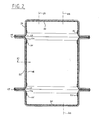
- FIG. 2 represents a variant of the type of containers capable of being produced by the same process.
- the container has three components: - Two shells (21) similar to the shells of the previous example, assembled on the two open ends provided with flaps of a ferrule (22) by autogenous welding using stainless metal cords (27).
- the metallized surfaces of the various constituent elements are (23) and (24).
- the heat-sensitive anticorrosion coatings are applied in layers (25), (26) overlapping the metallized layers (23), (24).
- Connection pipes (28) to (31) can be placed at different points of the finished container by applying the same technique as previously.
- the containers corresponding to FIG. 1 can be all types of flat tanks such as, for example, fuel tanks for automobiles.
- the vessels corresponding to FIG. 2 may be vessels of the type of reactors used in chemistry, or in pharmaceutical manufacturing processes or in the food industries.
Landscapes
- Engineering & Computer Science (AREA)
- Mechanical Engineering (AREA)
- Laminated Bodies (AREA)
- Details Of Rigid Or Semi-Rigid Containers (AREA)
- Rigid Containers With Two Or More Constituent Elements (AREA)
- Table Devices Or Equipment (AREA)
- Lining Or Joining Of Plastics Or The Like (AREA)
- Arc Welding In General (AREA)
- Compositions Of Macromolecular Compounds (AREA)
- Butt Welding And Welding Of Specific Article (AREA)
- Containers Having Bodies Formed In One Piece (AREA)
Abstract
Description
- La présente invention se situe dans le domaine de l'assemblage par soudure autogène de récipients constitués d'au moins deux pièces du type des réservoirs ou des réacteurs utilisés par les industries chimiques, alimentaires agrochimiques, pharmaceutiques etc...
- Les fluides transportés ou traités dans ces récipients s'entendent de la façon la plus générale tels que : solutions aqueuses, organiques, lessives chimiques, suspensions ou émulsions etc...
- Les récipients adaptés à ces transports ou traitement sont généralement en acier et reçoivent habituellement des revêtements protecteurs tels que ciment verré, émaux ou vernis cuits au four tels que vernis à base de résines époxy ou polyuréthannes etc... Ils peuvent également être réalisés en acier inox et sont alors dépourvus de revêtement.
- Les récipients en question sont limités dans leur forme étant donné que la susceptibilité thermique des revêtements cités plus haut interdit qu'ils soient fabriqués en plusieurs pièces et assemblés par soudure autogène des pièces constituants en acier. Par ailleurs les récipients obtenus par chaudronnerie à partir de feuilles d'acier inox sont trés onéreux.
- Le but de la présente invention est de remédier à ces inconvénients et limitations de façon simple.
- L'invention concerne en premier lieu des récipients métalliques composites constitués de deux coquilles assemblés par soudure, caractérisés en ce que les deux coquilles peuvent prendre appui l'une sur l'autre le long de replats périphériques plans dont la tranche est chanfreinée, ces replats et leurs tranches chanfreinées étant munis d'une couche métallique inoxydable se prolongeant vers l'intérieur du récipient terminé jusqu'au delà du congé de raccordement du replat et du corps du récipient, lequel récipient portant par ailleurs un revêtement anticorrosion constituée de résines thermoplastique ou de résines thermodurcissables, la couche anticorrosion étant telle qu'elle s'arrête à une distance d'au moins 15 mm de la zone où sera effectuée la soudure autogène et qu'elle chevauche la couche métallique sur une longueur d'au moins 10 mm et la soudure autogène étant réalisée par un cordon d'alliage inoxydable de même nature que la couche déposée sur les replats des deux coquilles.
- L'invention concerne également une technique de fabrication de ces récipients. Cette technique comporte une première phase qui consiste à déposer, notamment par schoopage, nom par lequel on entend en technologie l'application au chalumeau oxyacétylénique d'un métal introduit sous forme de fil continu dans le chalumeau, sur les portées planes ou replats des éléments de récipient à assembler, d'un alliage métallique inoxydable constitué de fer et de l'un des métaux du groupe chrome, nickel, cobalt.
- Dans une variante du procédé, l'alliage métallique inoxydable est injecté dans le chalumeau sous forme de poudre et contient, outre les métaux cités, du carbure de silicium.
- L'épaisseur d'alliage déposé varie suivant les applications de 200 à 600 microns.
- Le bord extérieur des replats à assembler est avantageusement chanfreiné suivant un angle compris entre 45 et 60° par rapport au plan d'assemblage.
- Non seulement les replats à assembler, mais aussi la tranche chanfreinée de la tôle de l'élément de récipient reçoivent ainsi une métallisation telle que décrite ci-dessus.
- Il a été trouvé avantageux de prolonger cette métallisation vers l'intérieur du récipient, au delà du rayon de raccordement du replat et du corps du récipient.
- Au cours d'une seconde phase du procédé on dépose sur la paroi intérieure de l'élément de récipient à assembler un revêtement anticorrosion qui peut être constitué de résines thermoplastiques choisies dans le groupe des polyamides, des résines fluorées, des polyéthylènes, de préférence de haut poids moléculaire ou du PVC. Ce revêtement peut également être constitué de résines thermodurcissables choisies dans le groupe des résines époxy ou polyuréthannes.
- Ces diverses résines thermoplastiques sont avantageusement mises en oeuvre à partir de poudres fines d'une granulométrie comprise entre 10 et 400 microns et par des procédés connus tels que le pou drage électrostatique, le trempage ou le pistolage. Suivant les cas l'épaisseur de ce revêtement peut varier de 200 microns à 5 mm.
- Une réserve est respectée sur le replat des éléments à assembler dans lequel l'alliage métallique inoxydable déposé lors de la première phase reste à nu.
- Le revêtement anticorrosion appliqué dans la deuxième phase est tel qu'il doit toujours recouvrir le dépôt métallique inoxydable de façon à assurer la continuité de la protection de l'intérieur du récipient obtenu.
- La création de tubulures éventuelles par assemblage de tronçons de cylindre au corps du récipient s'obtient de la même façon, en ayant prévu les ouvertures correspondantes sur le corps du récipient à obtenir.
- On respectera chaque fois le principe du recouvrement du revêtement métallique inoxydable par le revêtement thermoplastique anticorrosion. Pour des raisons de sécurité et de tolérances de fabrication industrielle, la zone de recouvrement (où les deux revêtements se chevauchent) ne doit pas être inférieure à 10 mm.
- On compendra mieux la disposition relative des couches des deux revêtements à l'aide des figures jointes à la présente description.
- La figure 1 représente en coupe un récipient formé de deux coquilles assemblées le long d'un plan de joint plan.
- La figure 2 représente une coupe d'un autre type de récipient formé de trois éléments assemblés le long de deux plans de joint distincts.
- Sur la figure 1, un récipient selon l'invention est constitué de deux coquilles (11) et (12) portant l'une sur l'autre par des replats le long du plan de joint (19). Ces replats reçoivent par schoopage une métallisation à base d'une composition inoxydable sur toutes les surfaces (13), (14) comprenant outre le replat proprement dit, une surface arrondie raccordant le replat à la cavité intérieure de la coquille (11) ou (12).
- Une couche de revêtement anticorrosion (11) et (12), à base de résines thermoplastiques choisies dans le groupe des polyamides, des résines fluorées des polyéthylènes ou du PVC, ou de résines thermodurcissables, telles que les résines époxy ou polyuréthannes.
- Ces deux familles de résines sont thermosensibles, les premières parce qu'elles fondent à leur température de fusion avant de se décomposer, les secondes parce qu'elles subissent une décomposition.
- L'objet de la présente invention est de soustraire le revêtement anticorrosion thermosensible à la décomposition, en l'arrêtant au moins à 15 mm de la zone où l'on procèdera à la soudure autogène des bords des coquilles à assembler.
- Cette soudure autogène sera obtenue par fusion d'un cordon (10) en alliage métallique inoxydable de même composition que les couches (13) et (14) déposées sur les replats des coquilles à assembler. Les tranches de la tôle de ces coquilles sont avantageusement chanfreinées vers l'intérieur du récipient terminé d'un angle comprise entre 45 et 60° sur l'horizontale du plan de joint, formant ainsi une gorge pour recevoir le métal du cordon de soudure.
- Le récipient terminé devant servir de réservoir il est nécessaire de prévoir des tubulures diverses telles que (17), (18). Le métal de ces tubulures sera métallisé par une composition inoxydable sur sa face intérieure et sa tranche et recevra en outre un revêtement anticorrosion suivant le même principe que celui énoncé plus haut, à savoir que le revêtement anticorrosion thermosensible est interrompu à au moins 15 mm de la tranche à assembler par soudure autogène, et que ce revêtement chevauche la couche métallique inoxydable sur une longueur d'au moins 10 mm.
- La figure 2 représente une variante du type de récipients susceptibles d'être produits par le même procédé. Le récipient comporte trois éléments constitutifs :
- Deux coquilles (21) semblables aux coquilles de l'exemple précédent, assemblées sur les deux extrémités ouvertes munies de replats d'une virole (22) par soudure autogène à l'aide de cordons métalliques inoxydables (27). Les portées métallisées des divers éléments constitutifs sont (23) et (24). - Les revêtements anticorrosion thermosensibles sont appliqués en couches (25), (26) chevauchant les couches métallisées (23), (24).
- Des tubulures de raccordement (28) à (31) peuvent être placés en différents points du récipient terminé en appliquant la même technique que précèdemment.
- Les récipients correspondant à la figure 1 peuvent être tous types de réservoirs plats tels que par exemple réservoirs de carburant pour automobiles.
- Les récipients correspondant à la figure 2 peuvent être des récipients du type des réacteurs employés en chimie, ou dans les procédés de fabrication pharmaceutiques ou dans les industries alimentaires.
Claims (4)
Priority Applications (1)
| Application Number | Priority Date | Filing Date | Title |
|---|---|---|---|
| AT86402579T ATE44007T1 (de) | 1985-11-26 | 1986-11-20 | Durch schweissung zusammengesetzter behaelter aus metall-plastikverbundwerkstoff. |
Applications Claiming Priority (2)
| Application Number | Priority Date | Filing Date | Title |
|---|---|---|---|
| FR8517475 | 1985-11-26 | ||
| FR8517475A FR2590550B1 (fr) | 1985-11-26 | 1985-11-26 | Recipients composites metalloplastiques assembles par soudure et leur procede de fabrication |
Publications (2)
| Publication Number | Publication Date |
|---|---|
| EP0227525A1 true EP0227525A1 (fr) | 1987-07-01 |
| EP0227525B1 EP0227525B1 (fr) | 1989-06-14 |
Family
ID=9325167
Family Applications (1)
| Application Number | Title | Priority Date | Filing Date |
|---|---|---|---|
| EP86402579A Expired EP0227525B1 (fr) | 1985-11-26 | 1986-11-20 | Récipients composites métalloplastiques assemblés par soudure |
Country Status (11)
| Country | Link |
|---|---|
| US (1) | US4753368A (fr) |
| EP (1) | EP0227525B1 (fr) |
| JP (1) | JPS62144944A (fr) |
| AT (1) | ATE44007T1 (fr) |
| CA (1) | CA1268433A (fr) |
| DE (1) | DE3663924D1 (fr) |
| DK (1) | DK166955B1 (fr) |
| ES (1) | ES2008856B3 (fr) |
| FR (1) | FR2590550B1 (fr) |
| GR (1) | GR3000100T3 (fr) |
| NO (1) | NO173132C (fr) |
Cited By (1)
| Publication number | Priority date | Publication date | Assignee | Title |
|---|---|---|---|---|
| EP0548750A1 (fr) * | 1991-12-24 | 1993-06-30 | FIAT AUTO S.p.A. | Réservoir de combustible pour voitures et procédé pour sa fabrication |
Families Citing this family (22)
| Publication number | Priority date | Publication date | Assignee | Title |
|---|---|---|---|---|
| NO160164C (no) * | 1986-06-13 | 1989-03-15 | Norsk Hydro As | Transportbeholder for vaeske/gass-proever. |
| DE8630024U1 (de) * | 1986-11-10 | 1987-03-19 | Remaplan GmbH, 8000 München | Profiliertes Kastenelement |
| JPH01293979A (ja) * | 1988-05-21 | 1989-11-27 | Eidai Co Ltd | 流し台等の天板製造方法 |
| US4982856A (en) * | 1989-06-23 | 1991-01-08 | General Electric Company | High temperature, high pressure continuous random glass fiber reinforced thermoplastic fluid vessel and method of making |
| US5129544A (en) * | 1990-11-08 | 1992-07-14 | Jacobson Wendell L | Laminated fuel tank structure |
| US5234286A (en) * | 1992-01-08 | 1993-08-10 | Kenneth Wagner | Underground water reservoir |
| DE4242370C1 (de) * | 1992-12-16 | 1994-05-11 | Schuetz Werke Gmbh Co Kg | Mehrwegfaß aus Kunststoff und Verfahren zu dessen Herstellung |
| US5547096A (en) * | 1994-12-21 | 1996-08-20 | Kleyn Die Engravers, Inc. | Plated polymeric fuel tank |
| DE59803789D1 (de) * | 1997-12-11 | 2002-05-16 | Verdichter Oe Ges M B H | Kältemittelverdichter mit verbesserter druckkammer |
| US6365115B1 (en) * | 1999-05-14 | 2002-04-02 | Poly Vac, Inc. | Sterilization and storage container tray |
| BE1012708A3 (fr) * | 1999-06-07 | 2001-02-06 | Solvay | Systeme a carburant pour vehicule. |
| DE19946530B4 (de) * | 1999-09-28 | 2007-01-25 | Ti Automotive Technology Center Gmbh | Doppelwandiger Kraftstoffbehälter |
| US6860398B2 (en) | 2000-11-30 | 2005-03-01 | Visteon Global Technologies, Inc. | Low permeation fittings, low permeation containers utilizing same, and methods for forming same |
| WO2002070399A1 (fr) * | 2001-03-06 | 2002-09-12 | Texas Research International, Inc. | Systeme d'hydratation chimiquement et biologiquement resistant |
| DE10138365A1 (de) * | 2001-08-04 | 2003-02-20 | Niro Plan Ag Zug | Einweg-Keg |
| US6722521B2 (en) | 2002-05-07 | 2004-04-20 | Visteon Global Technologies, Inc. | Low permeation pinchoff connection for bridging a barrier layer and method of making same |
| DE102006054208B4 (de) * | 2006-01-10 | 2016-04-07 | Erhard & Söhne GmbH | Behälter für Betriebsstoffe von Kraftfahrzeugen |
| US20070235458A1 (en) * | 2006-04-10 | 2007-10-11 | Mann & Hummel Gmbh | Modular liquid reservoir |
| FR2905268B1 (fr) * | 2006-09-01 | 2009-01-23 | Unither Dev Soc Par Actions Si | Substitut salivaire |
| KR20100015732A (ko) * | 2007-04-17 | 2010-02-12 | 슐저메트코(유에스)아이엔씨 | 보호 코팅 및 그것의 형성 방법 |
| CN102947781B (zh) | 2010-06-22 | 2016-03-09 | 日本写真印刷株式会社 | 具有防锈性的窄边框触摸输入薄片及其制造方法 |
| DE102018101884A1 (de) * | 2018-01-29 | 2019-08-01 | Bayerische Motoren Werke Aktiengesellschaft | Modular aufgebauter Kunststoffbehälter |
Citations (7)
| Publication number | Priority date | Publication date | Assignee | Title |
|---|---|---|---|---|
| CH217555A (de) * | 1939-06-29 | 1941-10-31 | Sauter Ag | Verfahren zur Herstellung von Boilern. |
| FR869239A (fr) * | 1940-01-15 | 1942-01-27 | Deutsche Rohrenwerke Ag | Joint de soudure autogène |
| DE723747C (de) * | 1936-10-07 | 1942-08-10 | Mannesmann Ag | Verfahren zum Stumpfschweissen von plattierten Blechen und Rohren |
| US2343315A (en) * | 1939-04-06 | 1944-03-07 | Willard L Morrison | Tank |
| FR1118100A (fr) * | 1953-12-09 | 1956-05-31 | Munk & Schmitz K G | Procédé pour produire des revêtements exempts de retrait pour réservoirs de toutes sortes au moment de matériaux métalliques résistant à la corrosion |
| DE1102707B (de) * | 1956-11-15 | 1961-03-23 | Hubert Salmen | Hohlkoerper, wie Behaelter, Rohrleitungen od. dgl., fuer korrodierend wirkende Stoffe |
| US3115987A (en) * | 1962-10-05 | 1963-12-31 | Gen Electric | Welded container with thermoplastic lining and method of making same |
Family Cites Families (7)
| Publication number | Priority date | Publication date | Assignee | Title |
|---|---|---|---|---|
| US1748138A (en) * | 1927-02-10 | 1930-02-25 | American Car & Foundry Co | Container for liquids or gases under pressure and method of making the same |
| US2145937A (en) * | 1935-02-12 | 1939-02-07 | Lockwood Isabel Tyte | Welding and welded joint |
| US2263021A (en) * | 1938-06-24 | 1941-11-18 | Smith Corp A O | Domestic hot water tank |
| US2302563A (en) * | 1940-09-25 | 1942-11-17 | Koch Butchers Supply Company | Porcelained metal structure and method of making the same |
| US2592419A (en) * | 1948-01-20 | 1952-04-08 | Sun Oil Co | Lead lined vessel |
| US2993617A (en) * | 1959-06-01 | 1961-07-25 | Rheem Mfg Co | Lined tank and method of making |
| US3268344A (en) * | 1965-01-19 | 1966-08-23 | American Can Co | Container and package utilizing the same |
-
1985
- 1985-11-26 FR FR8517475A patent/FR2590550B1/fr not_active Expired
-
1986
- 1986-11-20 DE DE8686402579T patent/DE3663924D1/de not_active Expired
- 1986-11-20 ES ES86402579T patent/ES2008856B3/es not_active Expired
- 1986-11-20 EP EP86402579A patent/EP0227525B1/fr not_active Expired
- 1986-11-20 AT AT86402579T patent/ATE44007T1/de not_active IP Right Cessation
- 1986-11-24 US US06/934,163 patent/US4753368A/en not_active Expired - Fee Related
- 1986-11-25 DK DK564586A patent/DK166955B1/da not_active IP Right Cessation
- 1986-11-25 CA CA000523759A patent/CA1268433A/fr not_active Expired - Lifetime
- 1986-11-25 NO NO864706A patent/NO173132C/no unknown
- 1986-11-26 JP JP61281607A patent/JPS62144944A/ja active Granted
-
1989
- 1989-07-08 GR GR89400113T patent/GR3000100T3/el unknown
Patent Citations (7)
| Publication number | Priority date | Publication date | Assignee | Title |
|---|---|---|---|---|
| DE723747C (de) * | 1936-10-07 | 1942-08-10 | Mannesmann Ag | Verfahren zum Stumpfschweissen von plattierten Blechen und Rohren |
| US2343315A (en) * | 1939-04-06 | 1944-03-07 | Willard L Morrison | Tank |
| CH217555A (de) * | 1939-06-29 | 1941-10-31 | Sauter Ag | Verfahren zur Herstellung von Boilern. |
| FR869239A (fr) * | 1940-01-15 | 1942-01-27 | Deutsche Rohrenwerke Ag | Joint de soudure autogène |
| FR1118100A (fr) * | 1953-12-09 | 1956-05-31 | Munk & Schmitz K G | Procédé pour produire des revêtements exempts de retrait pour réservoirs de toutes sortes au moment de matériaux métalliques résistant à la corrosion |
| DE1102707B (de) * | 1956-11-15 | 1961-03-23 | Hubert Salmen | Hohlkoerper, wie Behaelter, Rohrleitungen od. dgl., fuer korrodierend wirkende Stoffe |
| US3115987A (en) * | 1962-10-05 | 1963-12-31 | Gen Electric | Welded container with thermoplastic lining and method of making same |
Cited By (1)
| Publication number | Priority date | Publication date | Assignee | Title |
|---|---|---|---|---|
| EP0548750A1 (fr) * | 1991-12-24 | 1993-06-30 | FIAT AUTO S.p.A. | Réservoir de combustible pour voitures et procédé pour sa fabrication |
Also Published As
| Publication number | Publication date |
|---|---|
| JPH049632B2 (fr) | 1992-02-20 |
| NO173132C (no) | 1993-11-03 |
| DK564586D0 (da) | 1986-11-25 |
| FR2590550B1 (fr) | 1988-01-15 |
| DE3663924D1 (en) | 1989-07-20 |
| DK564586A (da) | 1987-05-27 |
| NO173132B (no) | 1993-07-26 |
| NO864706D0 (no) | 1986-11-25 |
| US4753368A (en) | 1988-06-28 |
| GR3000100T3 (en) | 1990-11-29 |
| FR2590550A1 (fr) | 1987-05-29 |
| CA1268433A (fr) | 1990-05-01 |
| DK166955B1 (da) | 1993-08-09 |
| EP0227525B1 (fr) | 1989-06-14 |
| ATE44007T1 (de) | 1989-06-15 |
| ES2008856B3 (es) | 1989-08-16 |
| JPS62144944A (ja) | 1987-06-29 |
Similar Documents
| Publication | Publication Date | Title |
|---|---|---|
| EP0227525B1 (fr) | Récipients composites métalloplastiques assemblés par soudure | |
| US5376410A (en) | Material surface modification | |
| JP5256257B2 (ja) | 自動車車軸成分と自動車車軸成分を製造する方法 | |
| FR2915450A1 (fr) | Procede de fabrication d'un cadre auxiliaire de vehicule automobile, et cadre auxiliaire ainsi obtenu | |
| FR2774352A1 (fr) | Element de renfort composite tridimensionnel pour vehicule automobile | |
| CA2701989C (fr) | Procede de fabrication d'un dispositif isolant tubulaire et dispositif correspondant | |
| FR2508860A1 (fr) | Axe de direction pour dispositif de direction destine a des vehicules automobiles | |
| CN86106439A (zh) | 自行车和类似装置的车架连接结构 | |
| GB1588834A (en) | Shell formed of plastics material for a sporting cartridge | |
| FR2550978A1 (fr) | Procede d'application de revetements de surface sur des articles | |
| JP4541588B2 (ja) | 容器蓋のための金属薄板からなるリング部材を形成する方法。 | |
| EP0726408B1 (fr) | Manchon antivibratoire hydraulique et son procédé de fabrication | |
| CA1295957C (fr) | Capacites composites metalloplastiques assemblees par soudure et leur procede de fabrication | |
| FR3128152A1 (fr) | Assemblage de multi-matériaux | |
| EP0340094A2 (fr) | Procédé d'assemblage par rivetage d'une première pièce en matière plastique et d'une seconde pièce. | |
| WO2008096060A2 (fr) | Procede de raccordement par soudage par friction d ' un tube | |
| EP0195474A2 (fr) | Palier à douille bridée et procédé pour sa fabrication | |
| FR2575320A1 (fr) | Emballage protecteur de longue duree contre la corrosion pour des colis fermes hermetiquement dont le contenu est hautement radioactif | |
| US4813590A (en) | Method for joining plastic components | |
| FR2918910A1 (fr) | Procede de fabrication d'un element de genie chimique | |
| EP3697548B1 (fr) | Couvercle pour boîte de conserve métallique, comprenant un anneau métallique et membrane pelable thermoscellée | |
| FR2781450A1 (fr) | Procede de fabrication d'un volant de direction | |
| FR2811386A1 (fr) | Procede de fabrication d'un manchon destine a accoupler deux arbres canneles et manchon d'accouplement obtenu par le procede | |
| EP0547982B1 (fr) | Procédé de fabrication d'un corps de distributeur à poche en métal, corps de distributeur et distributeur correspondant | |
| FR2572331A1 (fr) | Article embouti composite et procede pour sa fabrication |
Legal Events
| Date | Code | Title | Description |
|---|---|---|---|
| PUAI | Public reference made under article 153(3) epc to a published international application that has entered the european phase |
Free format text: ORIGINAL CODE: 0009012 |
|
| 17P | Request for examination filed |
Effective date: 19861125 |
|
| AK | Designated contracting states |
Kind code of ref document: A1 Designated state(s): AT BE CH DE ES FR GB GR IT LI LU NL SE |
|
| 17Q | First examination report despatched |
Effective date: 19880304 |
|
| GRAA | (expected) grant |
Free format text: ORIGINAL CODE: 0009210 |
|
| AK | Designated contracting states |
Kind code of ref document: B1 Designated state(s): AT BE CH DE ES FR GB GR IT LI LU NL SE |
|
| REF | Corresponds to: |
Ref document number: 44007 Country of ref document: AT Date of ref document: 19890615 Kind code of ref document: T |
|
| REF | Corresponds to: |
Ref document number: 3663924 Country of ref document: DE Date of ref document: 19890720 |
|
| GBT | Gb: translation of ep patent filed (gb section 77(6)(a)/1977) | ||
| ITF | It: translation for a ep patent filed | ||
| PLBE | No opposition filed within time limit |
Free format text: ORIGINAL CODE: 0009261 |
|
| STAA | Information on the status of an ep patent application or granted ep patent |
Free format text: STATUS: NO OPPOSITION FILED WITHIN TIME LIMIT |
|
| 26N | No opposition filed | ||
| REG | Reference to a national code |
Ref country code: GR Ref legal event code: FG4A Free format text: 3000100 |
|
| ITTA | It: last paid annual fee | ||
| PGFP | Annual fee paid to national office [announced via postgrant information from national office to epo] |
Ref country code: GB Payment date: 19931110 Year of fee payment: 8 Ref country code: FR Payment date: 19931110 Year of fee payment: 8 |
|
| PGFP | Annual fee paid to national office [announced via postgrant information from national office to epo] |
Ref country code: AT Payment date: 19931112 Year of fee payment: 8 |
|
| PGFP | Annual fee paid to national office [announced via postgrant information from national office to epo] |
Ref country code: CH Payment date: 19931115 Year of fee payment: 8 |
|
| PGFP | Annual fee paid to national office [announced via postgrant information from national office to epo] |
Ref country code: SE Payment date: 19931117 Year of fee payment: 8 |
|
| PGFP | Annual fee paid to national office [announced via postgrant information from national office to epo] |
Ref country code: DE Payment date: 19931123 Year of fee payment: 8 |
|
| PGFP | Annual fee paid to national office [announced via postgrant information from national office to epo] |
Ref country code: NL Payment date: 19931130 Year of fee payment: 8 Ref country code: GR Payment date: 19931130 Year of fee payment: 8 Ref country code: ES Payment date: 19931130 Year of fee payment: 8 |
|
| PGFP | Annual fee paid to national office [announced via postgrant information from national office to epo] |
Ref country code: LU Payment date: 19931201 Year of fee payment: 8 |
|
| PGFP | Annual fee paid to national office [announced via postgrant information from national office to epo] |
Ref country code: BE Payment date: 19940105 Year of fee payment: 8 |
|
| EPTA | Lu: last paid annual fee | ||
| PG25 | Lapsed in a contracting state [announced via postgrant information from national office to epo] |
Ref country code: LU Free format text: LAPSE BECAUSE OF NON-PAYMENT OF DUE FEES Effective date: 19941120 Ref country code: GB Effective date: 19941120 Ref country code: AT Effective date: 19941120 |
|
| PG25 | Lapsed in a contracting state [announced via postgrant information from national office to epo] |
Ref country code: SE Effective date: 19941121 Ref country code: ES Free format text: LAPSE BECAUSE OF EXPIRATION OF PROTECTION Effective date: 19941121 |
|
| PG25 | Lapsed in a contracting state [announced via postgrant information from national office to epo] |
Ref country code: LI Effective date: 19941130 Ref country code: CH Effective date: 19941130 Ref country code: BE Effective date: 19941130 |
|
| EAL | Se: european patent in force in sweden |
Ref document number: 86402579.6 |
|
| BERE | Be: lapsed |
Owner name: ATOCHEM Effective date: 19941130 |
|
| PG25 | Lapsed in a contracting state [announced via postgrant information from national office to epo] |
Ref country code: GR Free format text: THE PATENT HAS BEEN ANNULLED BY A DECISION OF A NATIONAL AUTHORITY Effective date: 19950531 |
|
| PG25 | Lapsed in a contracting state [announced via postgrant information from national office to epo] |
Ref country code: NL Effective date: 19950601 |
|
| NLV4 | Nl: lapsed or anulled due to non-payment of the annual fee | ||
| GBPC | Gb: european patent ceased through non-payment of renewal fee |
Effective date: 19941120 |
|
| PG25 | Lapsed in a contracting state [announced via postgrant information from national office to epo] |
Ref country code: FR Effective date: 19950731 |
|
| REG | Reference to a national code |
Ref country code: CH Ref legal event code: PL Ref country code: GR Ref legal event code: MM2A Free format text: 3000100 |
|
| PG25 | Lapsed in a contracting state [announced via postgrant information from national office to epo] |
Ref country code: DE Effective date: 19950801 |
|
| EUG | Se: european patent has lapsed |
Ref document number: 86402579.6 |
|
| REG | Reference to a national code |
Ref country code: FR Ref legal event code: ST |
|
| REG | Reference to a national code |
Ref country code: ES Ref legal event code: FD2A Effective date: 20010301 |
|
| PG25 | Lapsed in a contracting state [announced via postgrant information from national office to epo] |
Ref country code: IT Free format text: LAPSE BECAUSE OF NON-PAYMENT OF DUE FEES;WARNING: LAPSES OF ITALIAN PATENTS WITH EFFECTIVE DATE BEFORE 2007 MAY HAVE OCCURRED AT ANY TIME BEFORE 2007. THE CORRECT EFFECTIVE DATE MAY BE DIFFERENT FROM THE ONE RECORDED. Effective date: 20051120 |