EP0229182A1 - Anordnung zur einstellung einer optischen faser - Google Patents
Anordnung zur einstellung einer optischen faser Download PDFInfo
- Publication number
- EP0229182A1 EP0229182A1 EP86903568A EP86903568A EP0229182A1 EP 0229182 A1 EP0229182 A1 EP 0229182A1 EP 86903568 A EP86903568 A EP 86903568A EP 86903568 A EP86903568 A EP 86903568A EP 0229182 A1 EP0229182 A1 EP 0229182A1
- Authority
- EP
- European Patent Office
- Prior art keywords
- envelope
- creasing
- creasing lines
- lines
- pair
- Prior art date
- Legal status (The legal status is an assumption and is not a legal conclusion. Google has not performed a legal analysis and makes no representation as to the accuracy of the status listed.)
- Withdrawn
Links
- 239000011111 cardboard Substances 0.000 claims abstract description 52
- 239000010410 layer Substances 0.000 description 13
- QNRATNLHPGXHMA-XZHTYLCXSA-N (r)-(6-ethoxyquinolin-4-yl)-[(2s,4s,5r)-5-ethyl-1-azabicyclo[2.2.2]octan-2-yl]methanol;hydrochloride Chemical compound Cl.C([C@H]([C@H](C1)CC)C2)CN1[C@@H]2[C@H](O)C1=CC=NC2=CC=C(OCC)C=C21 QNRATNLHPGXHMA-XZHTYLCXSA-N 0.000 description 7
- 238000010276 construction Methods 0.000 description 7
- 239000000463 material Substances 0.000 description 4
- 230000004048 modification Effects 0.000 description 4
- 238000012986 modification Methods 0.000 description 4
- 230000001154 acute effect Effects 0.000 description 2
- 238000007789 sealing Methods 0.000 description 2
- 239000002344 surface layer Substances 0.000 description 2
- 239000000853 adhesive Substances 0.000 description 1
- 230000001070 adhesive effect Effects 0.000 description 1
- 239000000919 ceramic Substances 0.000 description 1
- 230000008878 coupling Effects 0.000 description 1
- 238000010168 coupling process Methods 0.000 description 1
- 238000005859 coupling reaction Methods 0.000 description 1
- 239000011521 glass Substances 0.000 description 1
- 239000011796 hollow space material Substances 0.000 description 1
- 239000004745 nonwoven fabric Substances 0.000 description 1
- 238000012856 packing Methods 0.000 description 1
- 230000001737 promoting effect Effects 0.000 description 1
- 230000000717 retained effect Effects 0.000 description 1
- 229920003002 synthetic resin Polymers 0.000 description 1
- 239000000057 synthetic resin Substances 0.000 description 1
Images







Classifications
-
- B—PERFORMING OPERATIONS; TRANSPORTING
- B65—CONVEYING; PACKING; STORING; HANDLING THIN OR FILAMENTARY MATERIAL
- B65D—CONTAINERS FOR STORAGE OR TRANSPORT OF ARTICLES OR MATERIALS, e.g. BAGS, BARRELS, BOTTLES, BOXES, CANS, CARTONS, CRATES, DRUMS, JARS, TANKS, HOPPERS, FORWARDING CONTAINERS; ACCESSORIES, CLOSURES, OR FITTINGS THEREFOR; PACKAGING ELEMENTS; PACKAGES
- B65D5/00—Rigid or semi-rigid containers of polygonal cross-section, e.g. boxes, cartons or trays, formed by folding or erecting one or more blanks made of paper
- B65D5/42—Details of containers or of foldable or erectable container blanks
- B65D5/44—Integral, inserted or attached portions forming internal or external fittings
- B65D5/50—Internal supporting or protecting elements for contents
- B65D5/5023—Integral elements for containers of other type, e.g. formed by folding a blank to U-shape
-
- B—PERFORMING OPERATIONS; TRANSPORTING
- B65—CONVEYING; PACKING; STORING; HANDLING THIN OR FILAMENTARY MATERIAL
- B65D—CONTAINERS FOR STORAGE OR TRANSPORT OF ARTICLES OR MATERIALS, e.g. BAGS, BARRELS, BOTTLES, BOXES, CANS, CARTONS, CRATES, DRUMS, JARS, TANKS, HOPPERS, FORWARDING CONTAINERS; ACCESSORIES, CLOSURES, OR FITTINGS THEREFOR; PACKAGING ELEMENTS; PACKAGES
- B65D5/00—Rigid or semi-rigid containers of polygonal cross-section, e.g. boxes, cartons or trays, formed by folding or erecting one or more blanks made of paper
- B65D5/18—Rigid or semi-rigid containers of polygonal cross-section, e.g. boxes, cartons or trays, formed by folding or erecting one or more blanks made of paper by folding a single blank to U-shape to form the base of the container and opposite sides of the body portion, the remaining sides being formed primarily by extensions of one or more of these opposite sides, e.g. flaps hinged thereto
-
- B—PERFORMING OPERATIONS; TRANSPORTING
- B65—CONVEYING; PACKING; STORING; HANDLING THIN OR FILAMENTARY MATERIAL
- B65D—CONTAINERS FOR STORAGE OR TRANSPORT OF ARTICLES OR MATERIALS, e.g. BAGS, BARRELS, BOTTLES, BOXES, CANS, CARTONS, CRATES, DRUMS, JARS, TANKS, HOPPERS, FORWARDING CONTAINERS; ACCESSORIES, CLOSURES, OR FITTINGS THEREFOR; PACKAGING ELEMENTS; PACKAGES
- B65D5/00—Rigid or semi-rigid containers of polygonal cross-section, e.g. boxes, cartons or trays, formed by folding or erecting one or more blanks made of paper
- B65D5/42—Details of containers or of foldable or erectable container blanks
- B65D5/44—Integral, inserted or attached portions forming internal or external fittings
- B65D5/50—Internal supporting or protecting elements for contents
- B65D5/5028—Elements formed separately from the container body
- B65D5/5035—Paper elements
-
- B—PERFORMING OPERATIONS; TRANSPORTING
- B65—CONVEYING; PACKING; STORING; HANDLING THIN OR FILAMENTARY MATERIAL
- B65D—CONTAINERS FOR STORAGE OR TRANSPORT OF ARTICLES OR MATERIALS, e.g. BAGS, BARRELS, BOTTLES, BOXES, CANS, CARTONS, CRATES, DRUMS, JARS, TANKS, HOPPERS, FORWARDING CONTAINERS; ACCESSORIES, CLOSURES, OR FITTINGS THEREFOR; PACKAGING ELEMENTS; PACKAGES
- B65D81/00—Containers, packaging elements, or packages, for contents presenting particular transport or storage problems, or adapted to be used for non-packaging purposes after removal of contents
- B65D81/02—Containers, packaging elements, or packages, for contents presenting particular transport or storage problems, or adapted to be used for non-packaging purposes after removal of contents specially adapted to protect contents from mechanical damage
Definitions
- the present invention relates to an envelope and an envelope element which are capable of protecting an article contained therein against an impact imparted thereto from the outside and an envelope which can readily extend it's internal shape in conformity with the shape of an article and, more particularly, to an envelope and an envelope element which are formed by using a laminated cardboard.
- An object of the present invention is to provide an envelope and an envelope element which are capable of both readily containing an article regardless of its nature and form, and carrying and storing the article without any damage.
- an internal space thereof in conformity with a shape of an article to be contained is readily obtained and the contained article is held so it does not move while pressing the article, the article can be contained, carried and stored under quite stable conditions, and, since the envelope and the envelope element possess sufficient buffer capability to guard against an impact imparted thereto from the outside, the article contained therein can be effectively protected.
- an envelope element consists of a cardboard including a relief portion having relief means.
- the relief means comprises a plurality of creasing lines, a cutout and a weak portion.
- an envelope blank and an envelope formed from the envelope blank comprise a front section and a back section integrally connected thereto at its one end edge via a creasing line, and include a relief portion having relief means in a portion near the creasing line.
- the envelope blank consists of a laminated cardboard of at least three layers consisting of a pair of cardboards and a corrugated cardboard inserted therebetween.
- the front or the back section is formed with an end flap for sealing the envelope.
- the front or the back section is formed with a side flap for sealing the side portion of the envelope.
- the relief means comprises a creasing line having a line cut or a score line and a cutout.
- the envelope blank consists of a cardboard in the preferred embodiments of the present invention
- the envelope blank may consists of a nonwoven fabric or a synthetic resin material.
- the creasing lines may be simply pressed to form fold lines without making the score lines.
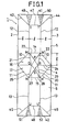
- a first relief portion having relief means including lines cut or score lines is formed. That is, pairs of first slant creasing lines 10, 10 and 11, 11 for forming an inside space of the envelope are arranged and extend from both ends of the creasing line 4 along the border between the front section 5 and the back section 6, and a pair of parallel creasing lines 14 and 15, substantially parallel with the creasing line 4, connect the other ends M, M' and N, N' of the slant creasing lines 10, 10 and 11, 11, respectively.
- pairs of second creasing lines 12, 12 and 13, 13 for forming the body of the envelope extend from the ends M, M' and N, N' of the first creasing lines 10, 10 and 11, 11 substantially in parallel with the side edges 2 and 3 of the envelope.
- first creasing lines 10, 10 and 11, 11 are readily folded due to the presence of the second creasing lines 12, 12 and 13, 13.
- a pair of reliefs 16 and 17 are formed via the creasing line 4 defining the border between the front section 5 and the back section 6. That is, one relief 16 is surrounded by the first slant creasing lines 10, 10, the horizontal creasing line 14 and the creasing line 4, and the other relief 17 is surrounded by the first slant creasing lines 11, 11, the horizontal creasing line 15 and the creasing line 4.
- Each relief 16 or 17 comprises a plurality of creasing lines formed on the inner surface of the assembled envelope and a rhombic cutout 30 formed in the central portion of the creasing line 4.
- the creasing lines formed on the inner surface of the front section 5 are four creasing lines 21, 22 23 and 24 connecting the ends M and M' of the first slant creasing lines 10, 10 and the vertices P, Q and R of the rhombic cutout 30. That is, the creasing line 21 is a creasing line having a segment MQ, the creasing line 22 is a line cut or score line having a segment MP in the cardboard B as shown in Fig. 3, the creasing line 23 is a score line having a segment M'P in the cardboard B, and the creasing line 24 is a creasing line having a segment M'R.
- the back section 6 is formed with four creasing lines 26, 27, 28 and 29 in a manner similar to those of the front section 5; that is, the two creasing lines 26 and 29 and the two score lines 27 and 28.
- the envelope is folded in two around the central creasing line 4 and the assembled envelope 1 is put into another envelope.
- an article is put in an inside hollow space composed of the front section 5 and the back section 6 while the inside of the envelope 1 is extended so as to open it by folding the first creasing lines 10 and 11 and the second creasing lines 12 and 13 and the triangular areas MM'P and SNN' arranged in the bottom portion of the envelope 1 are projected towards a top opening portion 40 of the envelope 1, as shown in Fig. 2. Accordingly, an article such as a bottle contained within the inside of the envelope 1, the bottom of the bottle being supported by the projected triangular areas, will, in the event it is dropped, be effectively protected from any damage.
- third slant creasing lines 43, 44, 45 and 46 connecting the ends T, T' and U, U' of the respective second creasing lines 12, 12 and 13, 13 and the opposite edges of the opposite free ends 41 and 42 of the front section 5 and the back section 6, and a pair of horizontal creasing lines 47 and 48 connecting the ends T, T' and U, U' of the second creasing lines 12, 12 and 13, 13, respectively, are formed.
- the envelope 1 when the article is put into the envelope 1 which is then put into another conventional envelope and a cover is closed, a package having a fixed form can be readily obtained and such packages can be effectively and stably stored in a stack. Further, when the envelope 1 is designed as a right hexagonal cylinder having a side with a length 1, as shown in Fig. 3, the inside containing space of the envelope can be effectively used.
- FIG. 4 there is shown another embodiment of the present invention.
- the embodiment of Fig. 4 differs from the embodiment of Fig. 1 in that a pair of side flaps 61a and 62a are provided on a front section 60 via side creasing lines 61 and 62, and an end flap 63a is provided on the front section 60 via a creasing line 63 on its front end side opposite to a central creasing line 65 of an envelope 70.
- the envelope 70 is sealed on its sides. Then, after putting an article into the envelope 70, the folded end flap 63a is stuck to the outer surface of the back section 66, and thus the envelope 70 is sealed.
- the side flaps 61a and 62a and the end flap 63a may be provided on the back section 66.
- the side flaps 61a and 62a may be provided on the back section 66 and the end flap 63a may be provided on the front section 60.
- the opening portion 40 of the envelope assembled as shown in Fig. 2 may be closed by using another means (the embodiment of Fig. 1) or the end flap 63a (the embodiment of Fig. 4).
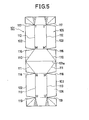
- an envelope 101 comprising a front section 105 and a back section 106 is symmetrically provided with first slant creasing lines 110, 110 and 111, 111 and second creasing lines 112, 112 and 113, 113 on the inner surfaces of the front and the back sections 105 and 106 via a central creasing line 101a in the same manner as the previous embodiments, except that reliefs contributing to the easy folding of the first creasing lines and the second creasing lines when an article containing space 150 is formed, and reliefs for enabling an cover to close are formed in the front section 105 and the back section 106.
- pairs of reliefs 116, 117, 118 and 119 having substantially the same acute vertical angle cutouts are formed, and the reliefs 116 and 117 of the front section 105 are symmetrical to the reliefs 118 and 119 of the back section 106 with respect to the central creasing line 101a.
- the reliefs 116 are triangular cutouts having vertices M and M' of the intersections of the first slant creasing lines 110, 110 and the second creasing lines 112, 112, and base parts of side end edges 102 and 103 of the envelope 101, and the reliefs 117 positioned in a higher position than the reliefs 116 are triangular cutouts of substantially the same form thereof, having vertices T and T' of the ends of the second creasing lines 112, 112, and the base parts of the side end edges 102 and 103.
- the back section 106 is formed with pairs of the reliefs 118, 118 and 119, 119 having the vertices N, N' and U, U' of the opposite ends of the second creasing lines 113, 113 in the same manner as the front section 105.
- the article is put in in the article containing space 150 of the envelope 101 and the envelope 101 is put into another envelope having a little larger size than the envelope 101.
- the first creasing lines and the second creasing lines are readily folded to form the article containing space.
- the cutouts are closed, and hence, even when an impact is imparted to the envelope from the outside, the article contained therein can be effectively protected.
- Figs. 7 - 9 there are shown modifications of the embodiment of Fig. 5.
- the front section 130 is formed with side flaps 131a, 132a, 135a, 136a, 140a and 141a via creasing lines 131, 132, 135, 136, 140 and 141, and an end flap 133a via a creasing line 133.
- the front section 144 and the back section 145 are each formed with pairs of reliefs of triangular cutouts 142, 142 and 143, 143, respectively, in the central portions in the longitudinal direction of the front and the back sections, and the other portions are the same as those of the embodiment of Fig. 5.
- a front section 146 is formed with side flaps 147a, 148a, l49a and 151a via creasing lines 147, 148, 149 and 151, and an end flap 152a via a creasing line 152.
- first and the second creasing lines are formed on the inner surfaces of the envelope, they may be formed on the outer surfaces of the envelope, or be formed on both the inner and the outer surfaces of the envelope.
- the assembling of the envelopes may be readily and quickly carried out.
- the front section and the back section are symmetrically connected to each other with reference to the central creasing line of the lower end of the front section
- the back section may be connected to the side edge of the front section or upper end edge thereof via a side or upper end creasing line.
- the weak portions described in connection with the embodiment of Fig. 1 may be formed in the cutout portions, and it is confirmed that the same function as the relief means may be obtained.
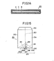
- an envelope 201 consists of the three-layer laminated cardboard consisting of a pair of cardboards A and B and a corrugated cardboard C interposed therebetween, in the same manner as the aforementioned embodiments (refer Fig. 14).
- the laminated cardboard is used so that the convex and the concave stripes of the corrugated cardboard C may extend substantially parallel with both the sides of the envelope 201, the laminated cardboard may be so used that the stripes may extend perpendicular to both the sides of the envelope 201.
- the envelope 201 formed from such a cardboard is provided with a front section 203, a back section 204 integrally connected thereto via a central creasing line 202, a pair of side flaps 205a and 206a integrally connected to both sides of the front section 203 via side creasing lines 205 and 206, and an end flap 207a integrally connected to the free end of the front section 203 via an end creasing line 207.
- pairs of first slant creasing lines 210, 210 and 211, 211 which extend from the ends of the central creasing line 202 are formed for extending the inside bottom portion of the envelope 201 when using the assembled envelope 201
- a pair of second creasing lines 212 and 213 which extend from the intersections M and N of the first slant creasing lines 210, 210 and 211, 211 to the free ends of the front section 203 and the back section 204 substantially parallel with the sides of the envelope 201 are formed for widening the inside body portion of the envelope 201 when using the assembled envelope 201.
- the first slant creasing lines 210 and 211 can be readily folded due to the presence of the second creasing lines 212 and 213.
- reliefs 215 defined by the first slant creasing lines 210, 210 and 211, 211 and the central creasing lines 202 for promoting the folding of the first creasing lines 210 and 211 and the second creasing lines 212 and 213 are provided on the front section 203 and the back section 204.
- the reliefs 215 comprise creasing lines 216 formed on the inner surfaces of the front section 203 and the back section 204, and creasing lines 217 formed on the outer surfaces thereof.
- each creasing line 216 consists of a central score line 216B and a pair of creasing lines 216A and 216C arranged in both the sides thereof, these three lines 216A, 216B and 216C extending from the central creasing line 202 to the first creasing lines 210, 210 or 211, 211 substantially in parallel with both the side ends of the front section 203 and the back section 204.
- Each creasing line 217 formed on the outer surface of the envelope 201 is inclined at an acute angle 0 and extends from a point P positioned on the other side of the intersection M or N of the first creasing lines, i.e., the outer surface of the front section 203 or the back section 204, to the central creasing line 202.
- a score line is a line cut as exemplified in Fig. 22A, Fig. 22B and Fig. 22C
- a creasing line is a line with a pressed concave portion as illustrated in Fig. 22D, Fig. 22E and Fig. 22F.
- the upper figures are elevational views of the score line or the creasing line and the lower figures are longitudinal cross sectional views of the upper figures.
- the inner lower end portions of the front and the back sections of the assembled envelope 201 are projected in inversed V-shaped forms towards the opposed inner surfaces, as shown in Fig. 13. Accordingly, when an article such as a bottle is contained within the assembled envelope 201, the bottom of the bottle is supported by the projected lower end portions of the envelope 201, thereby protecting the bottle from impact damage.
- the small isosceles triangular areas having the vertex point P shown in Fig. 11 and the base part of the central creasing line 202 may be formed with many random perforations or dash cuts passing through the laminated cardboard, as shown in the embodiment of Fig. 1, so as to form the weak portions of the relief portion.
- FIG. 15, 16A and 16B there is shown another embodiment of the present invention.
- an envelope 251 is formed with pairs of first slant creasing lines 261, 261 and a pair of second creasing lines 263 on its inner surface (creasing lines formed on an inner surface of a front section are not shown) in the same manner as the embodiment of Fig.
- a relief 265 for assisting the folding of the first and the second creasing lines comprises three score lines 266A, 266B and 266C formed on the inner surfaces of the front section 253 and the back section 254 substantially in parallel with both the sides of the envelope 251, two creasing lines 267 and 268 defining a small triangle QRS with a vertex point Q on the outer surface of the back section 254, a creasing line 269 extending from the point Q to the point T on the outer surface of the back section 254, and another creasing line 270 extending from a point U positioned on the other side of the front section 253 in a symmetrical position of the point T to a central creasing line 250.
- an envelope 301 has the same construction as the above described embodiment, except that pairs of first creasing lines 310, 310 and 311, 311 are formed for assisting the widening of a body portion of the envelope when using the assembled envelope 301, as shown in the figures, and a relief means 315 comprises parallel creasing lines 316A, 316C, score lines 316B and a rhombic cutout 319 formed substantially in a central portion of a central creasing line 318.
- the small rhombic cutout 319 of the assembled envelope 301 is usually closed by pressure due to the thickness of the material of the envelope 301, but the small rhombic cutout 319 effectively contributes to the extension of the inside space of the assembled envelope.
- the small rhombic cutout 319 is completely closed.
- the parallel creasing lines 316A and 316C may be replaced by the slant creasing lines 326A and 326C shown in Fig. 19.
- two cutouts 369A and 369B having a little larger size than the cutout 319 may be formed, as shown in Fig. 20.
- an envelope 352 is preferably provided with pairs of second creasing lines on the inner surfaces of front and back sections thereof, as shown in Fig. 20.
- the cutouts may be completely closed after putting the article into the envelope. Modifications of a combination of the cutout and the first creasing lines are illustrated in Fig. 21A - Fig. 21C. In addition, depending on the selection of the cardboard material, the cutout or cutouts may be omitted.
- first creasing lines and the second creasing lines are formed on the inner surface of the envelope in these embodiments, in a manner similar to the previously described embodiments, the first and the second creasing lines may be formed only on the outer surface of the envelope or on both the inner and the outer surfaces of the envelope, as shown in Figs. 23A and 23B.
- a multi-layer laminated cardboard such as a five-layer laminated cardboard obtained by adding a further corrugated cardboard and a flat cardboard to the three-layer laminated cardboard may also be used for an envelope, depending on its uses.
- FIGs. 24 - 31 there are shown embodiments of an envelope element and an envelope having the envelope elements according to the present invention.
- an envelope element 400 is formed from the same three-layer laminated cardboard as that of the above described embodiments, and the convex and the concave stripes of the corrugated cardboard of the laminated cardboard extend substantially parallel with both side edges 402 and 403 of the envelope element 400.
- the envelope element 400 thus formed from such a laminated cardboard is formed with a relief portion including relief means having score lines and creasing lines and so forth. That is, the envelope element 400 is formed with a pair of first slant creasing lines 410, 410 extending from opposite ends of a lower end 404, and a horizontal creasing line 414 connecting the ends M and M' of the first creasing lines 410, 410 substantially in parallel with the lower end 404.
- a pair of second creasing lines 412, 412 extend upwards from the ends M and M' of the first creasing lines 410, 410 substantially parallel with both the side end edges 402 and 403 of the envelope element 400.
- the envelope element 400 is provided with a relief portion 416 defined by the first creasing lines 410, 410, the horizontal creasing line 414 and the lower end 404.
- the relief portion 416 comprises a plurality of creasing lines and score lines formed on the outer surface layer of the three-layer laminated cardboard, and a triangular cutout 430 formed in the central portion of the lower end 404. That is, the creasing lines of the envelope element 400 are four creasing lines 421, 422, 423 and 424 which extend from the ends M and M' of the first creasing lines 410, 410 to the vertices PQR of the triangular cutout 430, and the two creasing lines 422 and 423 are score lines.
- a pair of third slant creasing lines 443 and 444 extend from the other ends T and T' of the second creasing lines 412, 412 to the opposite edges of the upper end 441, and a horizontal creasing line 447 extends between the ends T and T' of the second creasing lines 412, 412.
- a pair of small isosceles triangular areas having respective vertexes T and T' and base parts of the upper end 441 are formed with a large number of perforations or dash cuts passing through the three-layer laminated cardboard so as to obtain weak portions 449 and 450.
- the weak portions 449 and 450 and the creasing lines 443, 444 and 447 together function as a relief means and hence constitute a relief portion near the upper end 441 of the envelope element 400, along with the above described relief portion 416 in the lower portion of the envelope element 400.
- an envelope element 500 has a similar construction to that of the embodiment of Fig. 24, except that a pair of relief portions 516 and 516' having the same construction as the relief portion 416 of the embodiment of Fig. 24 are formed in portions of upper and lower ends 541 and 504 of the envelope element 500.
- creasing lines 522a, 523a, 522 and 523 are formed as score lines, each having a cutting line in an outer surface layer of a three-layer laminated cardboard.
- an envelope element 600 possesses a construction similar to that of the embodiment of Fig. 25, except that a pair of relief portions 616 and 616' having structures similar to those of the embodiment of Fig. 25 are formed in central portions of both sides 602 and 603 of the envelope element 600, and that a pair of weak portions 649 and 650 having the same constructions as those of the embodiment of Fig. 24 are formed in a portion near an upper end 641 of the envelope element 600.
- an envelope element 700 is formed with relief portions 716 and 716' having the same constructions as those of the aforementioned embodiments in portions of an upper end 741 and a right side 703, and a pair of weak portions 749 and 750 having constructions similar to those of the embodiment of Fig. 24 in a portion of a left side 702.
- a pair of envelope elements are put in a conventional envelope and an article is put between the envelope elements in order to advantageously protect the article.
- a pair of envelope elements are inserted into the conventional envelope, the same two envelope elements or two different envelope elements may be put into the usual envelope depending on the form and the kind of article to be contained.
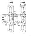
- Figs. 28 - 29 there are shown embodiments of an envelope consisting of envelope elements according to the present invention.
- Fig. 28 when the two envelope elements shown in Fig. 24 are symmetrically coupled to each other via a creasing line at an upper end 841, one side 802 or a lower end 804 of one of the envelope elements, an envelope as described in one of the above embodiments will be obtained.
- the envelope of the embodiment shown in Fig. 1 is obtained.
- Figs. 30 - 31 as schematically shown by imaginary lines thereof, when the two envelope elements of Fig. 26 or Fig. 27 are symmetrically connected to each other via a creasing line at an upper end, one side or a lower end of one of the envelope elements, an envelope of the present invention will be obtained. From these figures, it is readily understood that various changes and modifications of the envelope may be possible according to the present invention.
- more creasing lines 805, 806, 807 and 808 may be formed depending on the size of the article to be contained and the uses of the envelope.
- more creasing lines 905, 906, 907 and 908 may be formed, and, further, when the two envelope elements are coupled to each other via a creasing line at the one side 902, more creasing lines 909, 910, 911 and 912 may be formed.
Landscapes
- Engineering & Computer Science (AREA)
- Mechanical Engineering (AREA)
- Buffer Packaging (AREA)
- Cartons (AREA)
- Bag Frames (AREA)
Applications Claiming Priority (2)
| Application Number | Priority Date | Filing Date | Title |
|---|---|---|---|
| JP103522/85 | 1985-07-09 | ||
| JP1985103522U JPH0354043Y2 (de) | 1985-07-09 | 1985-07-09 |
Publications (2)
| Publication Number | Publication Date |
|---|---|
| EP0229182A1 true EP0229182A1 (de) | 1987-07-22 |
| EP0229182A4 EP0229182A4 (de) | 1987-11-09 |
Family
ID=14356259
Family Applications (1)
| Application Number | Title | Priority Date | Filing Date |
|---|---|---|---|
| EP19860903568 Withdrawn EP0229182A4 (de) | 1985-07-09 | 1986-05-24 | Anordnung zur einstellung einer optischen faser. |
Country Status (7)
| Country | Link |
|---|---|
| US (1) | US4809904A (de) |
| EP (1) | EP0229182A4 (de) |
| JP (1) | JPH0354043Y2 (de) |
| CN (1) | CN86103909A (de) |
| AU (1) | AU5908086A (de) |
| GB (1) | GB2187437A (de) |
| WO (1) | WO1987000145A1 (de) |
Families Citing this family (12)
| Publication number | Priority date | Publication date | Assignee | Title |
|---|---|---|---|---|
| US5236121A (en) * | 1991-06-28 | 1993-08-17 | Wollman Sandford L | Textile envelopes, cards and the like and methods of manufacture |
| US5626551A (en) * | 1995-01-13 | 1997-05-06 | Kearns; Elizabeth J. | Greeting card kit and method |
| CN1064621C (zh) * | 1997-07-11 | 2001-04-18 | 谭钢 | 一种复合料包装盒及其制造方法 |
| US7247214B2 (en) * | 2002-08-09 | 2007-07-24 | Paxar Corporation | Fabric garment label having detectable EAS or RFID marker in pocket and method of making same |
| US8307984B1 (en) * | 2011-05-26 | 2012-11-13 | Columbia Corrugated Box | Packaging insert for retaining an article within an exterior box |
| US9004345B2 (en) * | 2012-06-28 | 2015-04-14 | Conformer Products, Inc. | Blank for making a mailer and mailer made thereby |
| USD728971S1 (en) * | 2013-09-03 | 2015-05-12 | Paul Harris | Evacuation blanket |
| US9796509B2 (en) * | 2016-01-29 | 2017-10-24 | Bor-Jiun Huang | Origami envelope |
| US10351303B2 (en) | 2016-01-29 | 2019-07-16 | Bor-Jiun Huang | Origami envelope |
| US11713177B1 (en) * | 2019-07-31 | 2023-08-01 | Packaging Corporation Of America | Shipping mailer |
| MX2022005764A (es) | 2019-11-22 | 2022-08-08 | Pac Worldwide Corp | Contenedor de envio reciclable conformable. |
| MX2023000562A (es) | 2020-07-13 | 2023-02-13 | Pac Worldwide Corp | Envase de envio conformable y reciclable, maquina y metodo. |
Family Cites Families (21)
| Publication number | Priority date | Publication date | Assignee | Title |
|---|---|---|---|---|
| DE676708C (de) * | 1935-03-28 | 1939-06-10 | Vogt Processes Inc | Verpackung von Speiseeisportionen |
| CH263456A (de) * | 1948-05-21 | 1949-08-31 | Cafag Cartonnagenfabrik Freibu | Ampullenpackung. |
| GB962181A (en) * | 1962-04-30 | 1964-07-01 | Chambon Ltd | Improvements in or relating to cartons |
| GB1002622A (en) * | 1963-07-13 | 1965-08-25 | Cooke Ltd Alf | Cartons and like containers |
| JPS5025385B1 (de) * | 1968-07-02 | 1975-08-22 | ||
| US3726469A (en) * | 1970-08-17 | 1973-04-10 | A Koehler | Expansible and collapsible spring acting, multi-sided structures and blanks therefor |
| JPS4947339U (de) * | 1972-08-01 | 1974-04-25 | ||
| US3873017A (en) * | 1973-04-06 | 1975-03-25 | Franklin Container Corp | Corrugated polygonal container |
| JPS5010619U (de) * | 1973-05-29 | 1975-02-03 | ||
| JPS5153972Y2 (de) * | 1973-12-27 | 1976-12-23 | ||
| US3884352A (en) * | 1974-06-10 | 1975-05-20 | Container Corp | Book mailer |
| JPS5530853Y2 (de) * | 1974-07-01 | 1980-07-23 | ||
| JPS5313774A (en) * | 1976-07-24 | 1978-02-07 | Ricoh Co Ltd | Device for feeding stocked sheets |
| US4099664A (en) * | 1976-08-31 | 1978-07-11 | Swan Walter B | Bottom securement device for polygonal carton with bottom reinforcing ribs |
| US4164588A (en) * | 1977-12-06 | 1979-08-14 | The Procter & Gamble Company | Package liner and fragile snack chip combination |
| JPS5521939U (de) * | 1978-07-31 | 1980-02-13 | ||
| US4470540A (en) * | 1980-12-08 | 1984-09-11 | Koltz I Morton | Open top set up container |
| US4418861A (en) * | 1982-02-23 | 1983-12-06 | International Paper Company | Hexagonal container |
| JPH0510619A (ja) * | 1991-07-01 | 1993-01-19 | Mitsubishi Electric Corp | マルチ空気調和装置 |
| JP3110089B2 (ja) * | 1991-07-22 | 2000-11-20 | 三菱化学株式会社 | 樹脂組成物 |
| JPH05313774A (ja) * | 1992-05-12 | 1993-11-26 | Ricoh Co Ltd | ガイダンス表示装置 |
-
1985
- 1985-07-09 JP JP1985103522U patent/JPH0354043Y2/ja not_active Expired
-
1986
- 1986-05-24 EP EP19860903568 patent/EP0229182A4/de not_active Withdrawn
- 1986-05-24 AU AU59080/86A patent/AU5908086A/en not_active Abandoned
- 1986-05-24 GB GB08704879A patent/GB2187437A/en not_active Withdrawn
- 1986-05-24 US US07/044,843 patent/US4809904A/en not_active Expired - Fee Related
- 1986-05-24 WO PCT/JP1986/000266 patent/WO1987000145A1/ja not_active Ceased
- 1986-05-28 CN CN198686103909A patent/CN86103909A/zh active Pending
Also Published As
| Publication number | Publication date |
|---|---|
| AU5908086A (en) | 1987-01-30 |
| GB2187437A (en) | 1987-09-09 |
| US4809904A (en) | 1989-03-07 |
| EP0229182A4 (de) | 1987-11-09 |
| CN86103909A (zh) | 1987-01-07 |
| JPS6211732U (de) | 1987-01-24 |
| GB8704879D0 (en) | 1987-04-08 |
| JPH0354043Y2 (de) | 1991-11-27 |
| WO1987000145A1 (fr) | 1987-01-15 |
Similar Documents
| Publication | Publication Date | Title |
|---|---|---|
| EP0666218B1 (de) | Zuschnitt zur Herstellung einer leicht zu öffnenden amerikanischen Schachtel, sowie so hergestellte Schachtel | |
| RU2459754C1 (ru) | Упаковка и заготовка для ее формирования | |
| US4809904A (en) | Envelope element, envelope blank and envelope formed from the envelope blank | |
| RU2134652C1 (ru) | Усиленная ручка упаковочной коробки | |
| JPS63138945A (ja) | 液状内容物用包装容器 | |
| US5143213A (en) | Multi-pack flip-top cigarette carton | |
| JPH10273174A (ja) | 包装用緩衝材 | |
| JP2020169052A (ja) | 蓋体およびこれを備えた包装箱 | |
| CA1045062A (en) | Container and blanks therefor | |
| JP7021830B2 (ja) | 包装箱 | |
| JP7354917B2 (ja) | 包装箱 | |
| JP7102274B2 (ja) | 包装箱 | |
| FI71704B (fi) | Bottenkonstruktion foer pappersburk foer vaetskor | |
| JP3488311B2 (ja) | 段ボール箱 | |
| JPH1111529A (ja) | 包装用緩衝体及びその製造方法 | |
| US4603779A (en) | Glassware package | |
| JP7562235B2 (ja) | 包装箱 | |
| JP2003285823A (ja) | 緩衝板付カートン | |
| JP3244633U (ja) | 箱用シート | |
| JP7640967B2 (ja) | 包装容器、型紙及び梱包体 | |
| JP7375531B2 (ja) | 包装袋および包装袋用シート | |
| JP2007176528A (ja) | コーナ用梱包装置 | |
| JP3076635B2 (ja) | 果物の輸送・展示用箱 | |
| JP3648208B2 (ja) | 包装用箱 | |
| JPH0330289Y2 (de) |
Legal Events
| Date | Code | Title | Description |
|---|---|---|---|
| PUAI | Public reference made under article 153(3) epc to a published international application that has entered the european phase |
Free format text: ORIGINAL CODE: 0009012 |
|
| 17P | Request for examination filed |
Effective date: 19870323 |
|
| AK | Designated contracting states |
Kind code of ref document: A1 Designated state(s): BE DE FR IT |
|
| A4 | Supplementary search report drawn up and despatched |
Effective date: 19871109 |
|
| STAA | Information on the status of an ep patent application or granted ep patent |
Free format text: STATUS: THE APPLICATION IS DEEMED TO BE WITHDRAWN |
|
| 18D | Application deemed to be withdrawn |
Effective date: 19881201 |