EP0229280B1 - Moteur linéaire à structure plane pour impulsions - Google Patents
Moteur linéaire à structure plane pour impulsions Download PDFInfo
- Publication number
- EP0229280B1 EP0229280B1 EP86116569A EP86116569A EP0229280B1 EP 0229280 B1 EP0229280 B1 EP 0229280B1 EP 86116569 A EP86116569 A EP 86116569A EP 86116569 A EP86116569 A EP 86116569A EP 0229280 B1 EP0229280 B1 EP 0229280B1
- Authority
- EP
- European Patent Office
- Prior art keywords
- magnetic pole
- pole teeth
- pulse motor
- magnetic
- linear pulse
- Prior art date
- Legal status (The legal status is an assumption and is not a legal conclusion. Google has not performed a legal analysis and makes no representation as to the accuracy of the status listed.)
- Expired - Lifetime
Links
- 230000004907 flux Effects 0.000 claims abstract description 85
- 230000000712 assembly Effects 0.000 claims abstract description 7
- 238000000429 assembly Methods 0.000 claims abstract description 7
- 230000001939 inductive effect Effects 0.000 claims abstract description 6
- 230000005670 electromagnetic radiation Effects 0.000 claims description 31
- 230000008093 supporting effect Effects 0.000 claims description 11
- 239000002184 metal Substances 0.000 claims description 9
- 230000000630 rising effect Effects 0.000 claims description 2
- 238000010276 construction Methods 0.000 description 31
- 238000004519 manufacturing process Methods 0.000 description 24
- 230000007246 mechanism Effects 0.000 description 17
- 230000036961 partial effect Effects 0.000 description 14
- 230000008901 benefit Effects 0.000 description 13
- 230000002829 reductive effect Effects 0.000 description 10
- 230000002787 reinforcement Effects 0.000 description 8
- 230000003014 reinforcing effect Effects 0.000 description 8
- 230000007704 transition Effects 0.000 description 8
- 230000002441 reversible effect Effects 0.000 description 7
- 238000003754 machining Methods 0.000 description 5
- 238000005530 etching Methods 0.000 description 4
- 230000001976 improved effect Effects 0.000 description 4
- 230000001965 increasing effect Effects 0.000 description 4
- 230000000717 retained effect Effects 0.000 description 4
- 230000009471 action Effects 0.000 description 3
- 238000001514 detection method Methods 0.000 description 3
- 239000000463 material Substances 0.000 description 3
- 238000000034 method Methods 0.000 description 2
- 238000005096 rolling process Methods 0.000 description 2
- 238000004804 winding Methods 0.000 description 2
- 230000009286 beneficial effect Effects 0.000 description 1
- 239000002131 composite material Substances 0.000 description 1
- 238000010586 diagram Methods 0.000 description 1
- 230000000694 effects Effects 0.000 description 1
- 230000008030 elimination Effects 0.000 description 1
- 238000003379 elimination reaction Methods 0.000 description 1
- 208000028341 floppy head Diseases 0.000 description 1
- 238000002955 isolation Methods 0.000 description 1
- 239000006247 magnetic powder Substances 0.000 description 1
- 230000005415 magnetization Effects 0.000 description 1
- 238000000465 moulding Methods 0.000 description 1
- 238000003825 pressing Methods 0.000 description 1
- 230000008569 process Effects 0.000 description 1
- 230000009467 reduction Effects 0.000 description 1
- 230000000284 resting effect Effects 0.000 description 1
- 230000006641 stabilisation Effects 0.000 description 1
- 238000011105 stabilization Methods 0.000 description 1
- 229920003002 synthetic resin Polymers 0.000 description 1
- 239000000057 synthetic resin Substances 0.000 description 1
- 238000003466 welding Methods 0.000 description 1
Images


Classifications
-
- H—ELECTRICITY
- H02—GENERATION; CONVERSION OR DISTRIBUTION OF ELECTRIC POWER
- H02K—DYNAMO-ELECTRIC MACHINES
- H02K41/00—Propulsion systems in which a rigid body is moved along a path due to dynamo-electric interaction between the body and a magnetic field travelling along the path
- H02K41/02—Linear motors; Sectional motors
- H02K41/03—Synchronous motors; Motors moving step by step; Reluctance motors
- H02K41/031—Synchronous motors; Motors moving step by step; Reluctance motors of the permanent magnet type
- H02K41/033—Synchronous motors; Motors moving step by step; Reluctance motors of the permanent magnet type with armature and magnets on one member, the other member being a flux distributor
-
- G—PHYSICS
- G11—INFORMATION STORAGE
- G11B—INFORMATION STORAGE BASED ON RELATIVE MOVEMENT BETWEEN RECORD CARRIER AND TRANSDUCER
- G11B5/00—Recording by magnetisation or demagnetisation of a record carrier; Reproducing by magnetic means; Record carriers therefor
- G11B5/48—Disposition or mounting of heads or head supports relative to record carriers ; arrangements of heads, e.g. for scanning the record carrier to increase the relative speed
- G11B5/54—Disposition or mounting of heads or head supports relative to record carriers ; arrangements of heads, e.g. for scanning the record carrier to increase the relative speed with provision for moving the head into or out of its operative position or across tracks
- G11B5/55—Track change, selection or acquisition by displacement of the head
- G11B5/5521—Track change, selection or acquisition by displacement of the head across disk tracks
-
- H—ELECTRICITY
- H02—GENERATION; CONVERSION OR DISTRIBUTION OF ELECTRIC POWER
- H02K—DYNAMO-ELECTRIC MACHINES
- H02K2213/00—Specific aspects, not otherwise provided for and not covered by codes H02K2201/00 - H02K2211/00
- H02K2213/03—Machines characterised by numerical values, ranges, mathematical expressions or similar information
-
- H—ELECTRICITY
- H02—GENERATION; CONVERSION OR DISTRIBUTION OF ELECTRIC POWER
- H02K—DYNAMO-ELECTRIC MACHINES
- H02K7/00—Arrangements for handling mechanical energy structurally associated with dynamo-electric machines, e.g. structural association with mechanical driving motors or auxiliary dynamo-electric machines
- H02K7/08—Structural association with bearings
Definitions
- the present invention relates to a planar linear pulse motor, and more particularly relates to a planar linear pulse motor, of a type which is suitable for application for driving the movement of the magnetic head or heads in a floppy disk drive of a word processor or a personal computer or the like, which is improved in terms of thinness, overall size, assemblability, manufacturability, mountability, operational accuracy, and speed of operation.
- a cylindrical linear pulse motor comprising a stationary hollow cylindrical housing member 6 formed with a set of magnetic pole teeth denoted as 61 on its inner cylindrical surface, and a movable member 7 is slidably supported on a guide shaft 62, which extends substantially along the central axis of said cylindrical housing member 6, by a bearing construction 71 incorporating a bearing bush 72.
- This movable member 7 is formed with magnetic pole teeth 73 on its outer cylindrical surface, which cooperate with the magnetic pole teeth 61 of the cylindrical housing member 6 to linearly drive the movable member 7, according to suitable and selective magnetization of the movable member 7 in a per se known manner.
- a planar type linear pulse motor comprising a stationary assembly 1 and a planar movable member 5.
- the stationary assembly 1 and the movable member 5 thereof are mounted so as to be mutually slidable as shown by the arrow "A" in Fig. 8 by a means not particularly shown in the figures.
- the lower surface (not visible in the figure) of the planar movable member 5 is formed with a series 51 of magnetic pole teeth which are set in series at a pitch of P; and, as before, each of the magnetic pole teeth of this series 51 thereof is continuous from the left side to the right side thereof.
- the stationary assembly 1 comprises a plate shaped permanent magnet 2, having magnetic poles on its opposite side surfaces which are different in polarity but are the same along each said side surface, and extending substantially perpendicular to the direction of sliding motion of the planar movable member 5.
- a pair of magnetic core members 31a and 31b are provided, each being generally shaped like a letter "C", with central portions thereof denoted respectively as 31c and 31d being narrowed down somewhat and having coils 32a and 32b wound on them.
- the permanent magnet 2 for example by bonding.
- a back yoke 115 is fixed under the permanent magnet 2 for supporting it.
- the end portions 39a through 39d of the magnetic core members 31a and 31b are respectively formed directly as magnetic pole teeth portions 42a, 42b, 42c, and 42d with the upper surfaces thereof each being formed with a series of magnetic pole teeth 42a through 42d respectively, each said series being set at the same pitch P, and with the phases of the four series of magnetic pole teeth 42 arranged along the four magnetic pole teeth portions 42a, 42c, 42b, and 42d being staggered apart by a phase difference of P/4 in that order.
- the four magnetic pole teeth portions 42a, 42c, 42b, and 42d are sequentially magnetized in the one or the other polarity as required, and in cooperation with the magnetic biasing effect provided by the permanent magnet 2 they function to pull the planar movable member 5 along by its teeth 51 relative to the stationary assembly 1 by increments of one quarter of the pitch P of said teeth 51.
- planar linear pulse motor is fraught with the disadvantage of an inevitably excessive thickness, because the permanent magnet 2 and the back yoke 115 are layered together over the rear surfaces (the lower surface as seen in Fig. 8) of the magnetic core members 31a and 31b.
- Particular problems would arise when applying such a type of planar linear pulse motor for driving the movement of the magnetic head or heads in a floppy disk drive of a word processor or a personal computer or the like. For example, as schematically shown in Fig.
- planar linear pulse motor Another problem that arises in connection with the manufacture of such a planar linear pulse motor relates to the assembly thereof.
- a conceivable construction for such a planar linear pulse motor could be for a stationary member or base plate to be provided, and for a permanent magnet and four groups of magnetic pole teeth to be supported on said base plate.
- a guide mechanism for the planar movable member of the planar linear pulse motor could be provided, with a prestressing mechanism biasing said guide mechanism against said planar movable member and thus holding said planar movable member in a slidable manner.
- the problem would arise with such a construction that, since the permanent magnet and four groups of magnetic pole teeth would be required to be located on said base plate during manufacture, the positioning of said permanent magnet and said magnetic pole teeth during manufacture of the planar linear pulse motor could be rather difficult.
- linear pulse motors have not typically had any positioning mechanism for mounting them into other equipment.
- a linear pulse motor is to be installed into a system such for instance as a floppy head drive for a floppy disk drive for a word processor or a personal computer or the like, the advance shaft for the linear pulse motor and the central rotary shaft of the floppy disk drive must cross each other at right angles, and should any shifting or misalignment develop therebetween reading of information from the floppy disk loaded in the drive would inevitably become impossible.
- a linear pulse motor is to be installed into an apparatus such as a floppy disk drive, a high precision mounting jig is prepared, and the positioning of the linear pulse motor with respect to said apparatus is conducted with the aid of this jig prior to the actual mounting of the linear pulse motor.
- the use of such a jig means a requirement for extra time for the assembly of the device, and the need for a jig and the work required for preparing it inevitably raise the overall manufacturing cost.
- planar linear pulse motor Another problem that arises in connection with the manufacture of such a planar linear pulse motor relates to the detection of the position of the planar movable member thereof.
- a feed screw thread 41 is formed on a rotary shaft of a rotary pulse motor 4 while a screw thread hole 52 is formed in a support plate 5 which supports a magnetic head 6 and is supported by a straight guide, and the feed screw thread 41 is engaged to the screw thread hole 52 so as to convert the rotary motion of the pulse motor 4 into the linear motion of the magnetic head assembly 6.
- the origin or the start of the travel of the pulse motor 4 is defined at the outer most track of the floppy disk 7 fitted in the device by attaching a light shielding plate 53 to a part of the magnetic head support plate 5 and by placing a photo sensor unit 8 on the traveling path of this light shielding plate 53 so as to permit the adjustment of the light shielding position for the purpose of defining the relative position of the magnetic head 6 and the floppy disk 7.
- the photosensor unit 8 is typically one which is an off the shelf product which is large in external dimensions and is expensive, and this fact contributes to the large size and the high price of such a device. It has been proposed to apply a direct action type planar linear motor to such a magnetic head drive device, as for example in the previously discussed Japanese Patent Laying Open Publication No. 59-89565, but its travel origin detection mechanism is similar to the above described one, and the definition of the origin or start of travel thereof gives rise to similar problems.
- a planar linear pulse motor comprising first and second assemblies which are mutually movable along an axial line; said first assembly comprising a group of magnetic pole teeth, said magnetic pole teeth being arranged at a determinate pitch in a row along a line substantially parallel to said axial line, and each said magnetic pole tooth being elongated in a direction substantially perpendicular to said axial line; and said second assembly comprising: four groups of magnetic pole teeth, each said group being arranged substantially at said determinate pitch in a row along a line substantially parallel to said axial line, with the phases of said four groups of magnetic pole teeth being substantially offset from one another, and each said magnetic pole tooth being elongated in a direction substantially perpendicular to said axial line; said four groups of magnetic pole teeth of this second assembly each substantially confronting said group of magnetic pole teeth of said first assembly in a substantially parallel relationship with a relatively small gap being present therebetween; a permanent magnet having opposite magnetic poles on its
- planar linear pulse motor since the first assembly (which typically is the one of said first and second assemblies which is movable) and the second assembly (which typically is the one of said first and second assemblies which is fixed) are both planar in nature, as is a consequence of the second assembly being constituted by the pair of magnetic core members being fitted on opposite sides of the permanent magnet, thereby the thickness and the overall size of this planar linear pulse motor can be both reduced, and accordingly great advantages are obtained with regard to the fitting thereof to a device such as a floppy disk drive for a word processor or a personal computer or the like. Further, since the four groups of magnetic pole teeth of the second assembly can be formed by etching or by press forming or by some similar means, production precision can be kept high without any loss of production efficiency and without any unduly high cost being entailed.
- the above and other objects may more particularly be accomplished by such a planar linear pulse motor as first specified above, wherein said four groups of magnetic pole teeth of said second assembly are formed as portions of one integral magnetic pole teeth member; and optionally said magnetic pole teeth member may comprise strip portions which integrally join together said four groups of magnetic pole teeth.
- said magnetic pole teeth member may be formed generally in a hollow rectangular shape, with said four groups of magnetic pole teeth being located at its four corners and said strip portions being integrally joined to said four groups of magnetic pole teeth and extending along its edges.
- the above and other objects may more particularly be accomplished by such a planar linear pulse motor as first specified above, wherein said permanent magnet extends substantially parallel to said axial line.
- the above and other objects may more particularly be accomplished by such a planar linear pulse motor as first specified above, wherein said permanent magnet extends substantially perpendicular to said axial line.
- the above and other objects may more particularly be accomplished by such a planar linear pulse motor as first specified above, wherein said pair of magnetic core members and said four groups of magnetic pole teeth of said second assembly are all formed as portions of one unitary member.
- manufacturing efficiency is improved and manufacturing cost is reduced through simplification and unification of component parts of the second assembly, and the leakage of magnetic flux is avoided and the magnetic efficiency is improved through elimination of the otherwise inevitable bonded interfaces.
- the magnetic core members and the magnetic pole teeth portions of the second assembly are in this case made as one integral and unitary body, the size, in particular the thickness of the linear pulse motor can be reduced and various practical advantages can be obtained from this aspect of the construction, as well as from the aspect that the structure is simplified.
- said permanent magnet of said second assembly may be tightly fitted into a slot formed in said unitary member.
- said permanent magnet of said second assembly may be molded into a slot formed in said unitary member.
- the above and other objects may more particularly be accomplished by such a planar linear pulse motor as specified above, wherein said second assembly comprises a base member and a support wall rising up therefrom, said four groups of magnetic pole teeth being supported on either side of said permanent magnet on said base against said support wall.
- said support wall can be integrally formed with said base as a bent up tab portion thereof, and further can be formed with an extension adapted for mounting said planar linear pulse motor to another object.
- a means, such as a spring optionally supported by a spring mounting portion formed on said base can be provided for biasing said four groups of magnetic pole teeth and said permanent magnet against said support wall.
- the mutual positioning of the permanent magnet and the four groups of magnetic pole teeth can be conveniently and accurately performed, simply by mounting them with said four groups of magnetic pole teeth on either side of said permanent magnet resting on said base against said support wall, and by then either bonding these elements or biasing them by the aforementioned spring means (or both) against the support wall.
- the above and other objects may more particularly be accomplished by such a planar linear pulse motor as specified above, further comprising a means for mutually supporting said first and said second assembly with respect to one another so that they are mutually movable along said axial line, wherein said supporting means further comprises a means for positioning said planar linear pulse motor with respect to an element to which it is to be fitted; and, optionally but desirably, this supporting means may comprise a rail along which said first assembly slides, said positioning means comprising an extension of said rail at one or optionally at both of its ends.
- the supporting means can fulfill, not only its primary function of providing sliding mounting of the first and said second assembly with respect to one another, but also a function of thus aiding with the easy relative positioning of the planar linear pulse motor with respect to said element to which it is to be fitted.
- This economy of means is very convenient and economical of parts, and effectively eliminates the need for any special jig to be utilized during assembly of the planar linear pulse motor to said element to which it is to be fitted, which lowers overall manufacturing cost.
- the above and other objects may alternatively particularly be accomplished by such a planar linear pulse motor as first specified above, further comprising a means for detecting the position of said first assembly with respect to said second assembly.
- said position detecting means may comprise: a electromagnetic radiation shielding element fitted to said first assembly; and a electromagnetic radiation emitting element and a electromagnetic radiation receiving element fitted to said second assembly; said electromagnetic radiation shielding element, when said first assembly is in a determinate position with respect to said second assembly, interrupting electromagnetic radiation passing from said electromagnetic radiation emitting element to said electromagnetic radiation receiving element; but said electromagnetic radiation shielding element, when on the other hand said first assembly is not in said determinate position with respect to said second assembly, not thus interrupting electromagnetic radiation passing from said electromagnetic radiation emitting element to said electromagnetic radiation receiving element.
- Figs. 1, 2, and 3a through 3d relate to the first preferred embodiment of the planar linear pulse motor of the present invention.
- the reference numeral 1 denotes a stationary assembly thereof, while the reference numeral 5 refers to a movable member thereof, slidably mounted with respect to the stationary assembly 1 as shown by the arrow "A" in the figures.
- the stationary assembly 1 which is shown by itself in Fig. 2, comprises a permanent magnet 2 which is shaped as a prism (a rectangular prism in this preferred embodiment), and at each of its ends, only one of which is shown in the figures, this permanent magnet 2 has magnetic poles on its opposite side surfaces which are different in polarity but are the same along each said side surface: in the exemplary configuration of Fig. 1, the left side surface of the permanent magnet 2 at its end nearest to the viewer is a north or N pole, while the right side surface of said permanent magnet 2 at its end nearest to the viewer is a south or S pole. And, particularly in this first preferred embodiment of the planar linear pulse motor of the present invention, the permanent magnet 2 extends in the direction of sliding motion of the planar movable member 5, as will be explained later.
- a pair of magnetic core members 31a and 31b are provided, each being generally shaped like a letter "C", with central portions thereof denoted respectively as 31c and 31d being narrowed down somewhat.
- the one end portion designated as 39a in the figures of the one 31a of these magnetic core members is applied against, i.e. is fixed in direct contact with, the left side surface in the figures of the permanent magnet 2 at its end farthest from the viewer which is exemplarily shown as being a north or N pole - for example by being bonded thereto; the other end portion designated as 39b in the figures of said one magnetic core member 31a is applied against, i.e.
- a coil 32a is wound around the narrowed down portion 31c of the magnetic core member 31a, while similarly a coil 32b is wound around the narrowed down portion 31d of the magnetic core member 31b.
- a magnetic pole plate member 4 is fixed, as for example by being bonded, across the upper surfaces in the figure of the end portions 39a through 39d of the magnetic core members 31a and 31b, around the two ends of the upper surface in the figure of the permanent magnet 2, so as to be securely held relatively closely to said upper surfaces of said end portions 39a through 39d, so as to allow relatively easy passage of magnetic flux between itself and them.
- the magnetic pole plate member 4 is formed as a hollow rectangular member, with a rectangular cut out hole 41 in its central portion which corresponds to the upper surface of the permanent magnet 2, with relatively wide magnetic pole teeth portions 42a, 42b, 42c, and 42d at the corner end portions of the long sides of said rectangular cut out hole 41 in positions which correspond respectively to the upper surfaces of the end portions 39a, 39b, 39c, and 39d of the magnetic core members 31a and 31b, with relatively thin connecting portions 43 extending along the short sides of said rectangular cut out hole 41 which thus join together the magnetic pole teeth portions 42a and 42d and join together the magnetic pole teeth portions 42b and 42c, and with relatively thin connecting portions 44 extending along said long sides of said rectangular cut out hole 41 which thus join together the magnetic pole teeth portions 42a and 42b and join together the magnetic pole teeth portions 42c and 42d.
- each of the upper surfaces of each of these magnetic pole teeth portions 42a through 42d is formed with a series of magnetic pole teeth 42, the ones of these magnetic pole teeth 42 arranged along each particular one of said magnetic pole teeth portions 42a through 42d being set in series at the same pitch, designated in Fig.
- phase of the series of these magnetic pole teeth 42 arranged along the magnetic pole teeth portion 42a being set at a phase difference of P/2 from the phase of the series of the magnetic pole teeth 42 arranged along the magnetic pole teeth portion 42b
- phase of the series of the magnetic pole teeth 42 arranged along the magnetic pole teeth portion 42c being likewise set at a phase difference of P/2 from the phase of the series of the magnetic pole teeth 42 arranged along the magnetic pole teeth portion 42d
- the phase of the series of the magnetic pole teeth 42 arranged along the magnetic pole teeth portion 42a being set at a phase difference of P/4 from the phase of the series of the magnetic pole teeth 42 arranged along the magnetic pole teeth portion 42d
- the phase of the series of the magnetic pole teeth 42 arranged along the magnetic pole teeth portion 42b being consequently and likewise set at a like phase difference of P/4 from the phase of the series of the magnetic pole teeth 42 arranged along the magnetic pole teeth portion 42c.
- the lower surface (not visible in the figures) of the slidably mounted planar movable member 5 is formed with a series 51 of magnetic pole teeth which are set in series at the same pitch P as the magnetic pole teeth on each of the magnetic pole teeth portions 42a through 42d.
- this planar movable member 5 is slidably mounted, by a linear bearing type construction not shown in the figures, so as to be movable with respect to the stationary assembly 1 to and fro in the direction shown by an arrow "A" in the figures, and so that the teeth series 51 on its lower surface opposes the magnetic pole teeth on the magnetic pole teeth portions 42a through 42d with a relatively small gap, typically about 50 microns, being left therebetween.
- Each of the magnetic pole teeth of the series 51 thereof on the planar movable member 5 is continuous from the left side thereof which can correspond to one of the teeth of the magnetic pole teeth portion 42a or 42d to the right side thereof which can correspond to one of the teeth of the magnetic pole teeth portion 42b or 42c.
- the reference numeral 25 denotes the magnetic flux generated by the permanent magnet 2
- the reference numeral 33 denotes magnetic flux generated by one or the other of the magnetic coils 32a or 32b.
- the magnetic flux between the magnetic pole teeth on the magnetic pole teeth portion 42a of the magnetic pole plate member 4 and the opposing ones of the magnetic pole teeth of the series 51 thereof on the planar movable member 5 is strengthened, while on the other hand the magnetic flux between the magnetic pole teeth on the magnetic pole teeth portion 42b of said magnetic pole plate member 4 and the opposing ones of the magnetic pole teeth of the series 51 thereof on the planar movable member 5 is weakened; and, because the connecting portions 44 of the magnetic pole plate member 4 are relatively thin and accordingly have relatively high magnetic resistance and are also easily subject to magnetic saturation, the magnetic fluxes between the magnetic pole teeth on the magnetic pole teeth portions 42c and 42d of said magnetic pole plate member 4 and the opposing ones of the magnetic pole teeth of the series 51 thereof on the planar movable member 5 are substantially unaffected.
- the connecting portions 43 of the magnetic pole plate member 4 are also relatively thin and accordingly have relatively high magnetic resistance and are also easily subject to magnetic saturation, little leakage of the above described magnetic flux lines 33 directly between the two ends of the magnetic core member 31a can occur through them. And, as a result of the above described mutual reinforcement and cancellation of the permanent magnetic flux lines 25 and induced magnetic flux lines 33, a linear force is induced in the direction shown by the arrow "A" in the figure which tends to bring the magnetic pole teeth on said magnetic pole teeth portion 42a of said magnetic pole plate member 4 and the opposing ones of the magnetic pole teeth of the series 51 thereof on the planar movable member 5 together, while on the other hand separating the magnetic pole teeth on said magnetic pole teeth portion 42b of said magnetic pole plate member 4 and the opposing ones of the magnetic pole teeth of the series 51 thereof on the planar movable member 5.
- the magnetic flux between the magnetic pole teeth on the magnetic pole teeth portion 42c of the magnetic pole plate member 4 and the opposing ones of the magnetic pole teeth of the series 51 thereof on the planar movable member 5 is strengthened, while on the other hand the magnetic flux between the magnetic pole teeth on the magnetic pole teeth portion 42d of said magnetic pole plate member 4 and the opposing ones of the magnetic pole teeth of the series 51 thereof on the planar movable member 5 is weakened; and, again, because the connecting portions 44 of the magnetic pole plate member 4 are relatively thin, the magnetic fluxes between the magnetic pole teeth on the magnetic pole teeth portions 42a and 42b of said magnetic pole plate member 4 and the opposing ones of the magnetic pole teeth of the series 51 thereof on the planar movable member 5 are substantially unaffected.
- phase difference between the magnetic pole teeth on the magnetic pole teeth portion 42a of the magnetic pole plate member 4 and the magnetic pole teeth on the magnetic pole teeth portion 42c thereof is set, as explained above, to be P/4, the transition from the state of the apparatus shown by Fig. 3a to the state of the apparatus shown by Fig. 3b proceeds relatively smoothly, and the planar movable member 5 is smoothly propelled along.
- the magnetic flux between the magnetic pole teeth on the magnetic pole teeth portion 42b of the magnetic pole plate member 4 and the opposing ones of the magnetic pole teeth of the series 51 thereof on the planar movable member 5 is strengthened, while on the other hand the magnetic flux between the magnetic pole teeth on the magnetic pole teeth portion 42a of said magnetic pole plate member 4 and the opposing ones of the magnetic pole teeth of the series 51 thereof on the planar movable member 5 is weakened; and, again, because the connecting portions 44 of the magnetic pole plate member 4 are relatively thin, the magnetic fluxes between the magnetic pole teeth on the magnetic pole teeth portions 42c and 42d of said magnetic pole plate member 4 and the opposing ones of the magnetic pole teeth of the series 51 thereof on the planar movable member 5 are substantially unaffected.
- phase difference between the magnetic pole teeth on the magnetic pole teeth portion 42c of the magnetic pole plate member 4 and the magnetic pole teeth on the magnetic pole teeth portion 42b thereof is set, as also explained above, to be P/4, the transition from the state of the apparatus shown by Fig. 3b to the state of the apparatus shown by Fig. 3c proceeds relatively smoothly, and the planar movable member 5 is further smoothly propelled along.
- the magnetic flux between the magnetic pole teeth on the magnetic pole teeth portion 42d of the magnetic pole plate member 4 and the opposing ones of the magnetic pole teeth of the series 51 thereof on the planar movable member 5 is strengthened, while on the other hand the magnetic flux between the magnetic pole teeth on the magnetic pole teeth portion 42c of said magnetic pole plate member 4 and the opposing ones of the magnetic pole teeth of the series 51 thereof on the planar movable member 5 is weakened; and, again, because the connecting portions 44 of the magnetic pole plate member 4 are relatively thin, the magnetic fluxes between the magnetic pole teeth on the magnetic pole teeth portions 42a and 42b of said magnetic pole plate member 4 and the opposing ones of the magnetic pole teeth of the series 51 thereof on the planar movable member 5 are substantially unaffected.
- phase difference between the magnetic pole teeth on the magnetic pole teeth portion 42b of the magnetic pole plate member 4 and the magnetic pole teeth on the magnetic pole teeth portion 42d thereof is set, as also explained above, to be P/4, the transition from the state of the apparatus shown by Fig. 3c to the state of the apparatus shown by Fig. 3d proceeds relatively smoothly, and the planar movable member 5 is yet further smoothly propelled along.
- the transition from the state of the apparatus shown by Fig. 3d to the state of the apparatus shown by Fig. 3a proceeds relatively smoothly, and the planar movable member 5 is yet further smoothly propelled along.
- the coils 32a and 32b are alternately energized in alternating directions, as for example by a supply of four phase electrical current, the planar movable member 5 is smoothly driven, so as to smoothly move an object attached thereto, for example the magnetic head or heads of a floppy disk drive for a word processor or a portable computer.
- the sequence of such electrical supply to the coils 32a and 32b should be reversed appropriately.
- the magnetic pole plate member 4 can be made by a simple process, such as by pressing, by punch forming, or by etching or the like, which has a high production efficiency, therefore the cost of the planar linear pulse motor of the present invention can be reduced as compared to prior art such pulse motors.
- planar linear pulse motor of the present invention can be compact and small in overall size, and particularly can be thin in the vertical direction (from the point of view of the figures). This is very beneficial with regard to the intended application of this planar linear pulse motor, which as described above is for driving the movement of the magnetic head or heads in a floppy disk drive of a word processor or a personal computer or the like.
- FIG. 5a through 5d The construction and the functioning of the second preferred embodiment of the planar linear pulse motor of the present invention is shown in perspective view in Figs. 5a through 5d, with the gap between the stationary assembly 1 and the planar movable member 5 thereof grossly exaggerated, in a similar fashion to the illustrations of the functioning of the first preferred embodiment of the planar linear pulse motor of the present invention shown in Figs. 3a through 3d and described above.
- parts and gaps and spaces and so on which correspond to analogous parts and gaps and spaces and so on of the first preferred embodiment are denoted by reference numerals like to those utilized in the figures relating to said first preferred embodiment.
- This second preferred embodiment planar linear pulse motor is constructed in a fashion different from, but analogous to, the first preferred embodiment described above. Specifically, the permanent magnet 2 of this second preferred embodiment, rather than extending parallel to the direction of sliding motion of the planar movable member 5, instead extends substantially perpendicular to said sliding motion direction, as will be explained in the following.
- the stationary assembly 1 thereof and the movable member 5 thereof are mounted so as to be mutually slidable as shown by the arrow "A" in the figures.
- the lower surface (not visible in the figures) of the slidably mounted planar movable member 5 is formed with a series 51 of magnetic pole teeth which are set in series at a pitch of P; and, as before, each of the magnetic pole teeth of this series 51 thereof is continuous from the left side to the right side thereof.
- the stationary assembly 1 comprises a permanent magnet 2 which is again shaped as a rectangular prism, and at each of its ends, only one of which is shown in the figures, this permanent magnet 2 has magnetic poles on its opposite side surfaces which are different in polarity but are the same along each said side surface: as before, in the exemplary configuration of the figures, the left side surface of the permanent magnet 2 at its end nearest to the viewer is a north or N pole, while the right side surface of said permanent magnet 2 at its end nearest to the viewer is a south or S pole.
- the permanent magnet 2 extends substantially perpendicular to the direction of sliding motion of the planar movable member 5, i.e.
- a pair of magnetic core members 31a and 31b are provided, each being generally shaped like a letter “C", with central portions thereof denoted respectively as 31c and 31d being narrowed down somewhat.
- the one end portion designated as 39a in the figures of the one 31a of these magnetic core members is applied against, i.e. is fixed in direct contact with, the left side surface in the figures of the permanent magnet 2 at its end farthest from the viewer which is exemplarily shown as being a north or N pole - for example by being bonded thereto; the other end portion designated as 39b in the figures of said one magnetic core member 31a is applied against, i.e.
- a coil 32a is wound around the narrowed down portion 31c of the magnetic core member 31a, while similarly a coil 32b is wound around the narrowed down portion 31d of the magnetic core member 31b.
- the phase of the series of these magnetic pole teeth 42 arranged along the magnetic pole teeth portion 42a is set at a phase difference of P/2 from the phase of the series of the magnetic pole teeth 42 arranged along the magnetic pole teeth portion 42b, with the phase of the series of the magnetic pole teeth 42 arranged along the magnetic pole teeth portion 42c being likewise set at a phase difference of P/2 from the phase of the series of the magnetic pole teeth 42 arranged along the magnetic pole teeth portion 42d, with the phase of the series of the magnetic pole teeth 42 arranged along the magnetic pole teeth portion 42a being set at a phase difference of P/4 from the phase of the series of the magnetic pole teeth 42 arranged along the magnetic pole teeth portion 42d, and with therefore the phase of the series of the magnetic pole teeth 42 arranged along the magnetic pole teeth portion 42b being consequently and likewise set at a like phase difference of P/4 from the phase of the series of the magnetic pole teeth 42 arranged along the magnetic pole teeth portion 42c.
- FIG. 5a through 5d This second preferred embodiment of the planar linear pulse motor of the present invention operates as will now be described with reference to Figs. 5a through 5d.
- the reference numeral 25 denotes the magnetic flux generated by the permanent magnet 2
- the reference numeral 33 denotes magnetic flux generated by one or the other of the magnetic coils 32a or 32b.
- the lines of this permanent magnetic flux 25 proceed from the left side in the figures of the permanent magnet 2 which is a north or N pole, into one or the other of the end portions 39a or 39b of the magnetic core member 31a, thence through one or another of the magnetic pole teeth on the magnetic pole teeth portions 42a or 42b respectively affixed to said magnetic core member end portion, across the relatively narrow gap between said magnetic pole tooth on said magnetic pole teeth portion 42a or 42b to an opposing or nearly opposing one of the magnetic pole teeth of the series 51 thereof on the planar movable member 5, along through said magnetic pole tooth of said series 51, again across the relatively narrow gap between said magnetic pole tooth of said series 51 to an opposing or nearly opposing one of the magnetic pole teeth on the magnetic pole teeth portion 42d or 42c respectively, finally to return to the right side in the
- the magnetic flux between the magnetic pole teeth on the magnetic pole teeth portion 42d of the magnetic pole plate member 4 and the opposing ones of the magnetic pole teeth of the series 51 thereof on the planar movable member 5 is strengthened, while on the other hand the magnetic flux between the magnetic pole teeth on the magnetic pole teeth portion 42c of said magnetic pole plate member 4 and the opposing ones of the magnetic pole teeth of the series 51 thereof on the planar movable member 5 is weakened.
- the magnetic flux between the magnetic pole teeth on the magnetic pole teeth portion 42b of the magnetic pole plate member 4 and the opposing ones of the magnetic pole teeth of the series 51 thereof on the planar movable member 5 is strengthened, while on the other hand the magnetic flux between the magnetic pole teeth on the magnetic pole teeth portion 42a of said magnetic pole plate member 4 and the opposing ones of the magnetic pole teeth of the series 51 thereof on the planar movable member 5 is weakened.
- phase difference between the magnetic pole teeth on the magnetic pole teeth portion 42d of the magnetic pole plate member 4 and the magnetic pole teeth on the magnetic pole teeth portion 42b thereof is set, as explained above, to be P/4, the transition from the state of the apparatus shown by Fig. 5a to the state of the apparatus shown by Fig. 5b proceeds relatively smoothly, and the planar movable member 5 is smoothly propelled along.
- the magnetic flux between the magnetic pole teeth on the magnetic pole teeth portion 42c of the magnetic pole plate member 4 and the opposing ones of the magnetic pole teeth of the series 51 thereof on the planar movable member 5 is strengthened, while on the other hand the magnetic flux between the magnetic pole teeth on the magnetic pole teeth portion 42d of said magnetic pole plate member 4 and the opposing ones of the magnetic pole teeth of the series 51 thereof on the planar movable member 5 is weakened.
- phase difference between the magnetic pole teeth on the magnetic pole teeth portion 42b of the magnetic pole plate member 4 and the magnetic pole teeth on the magnetic pole teeth portion 42c thereof is set, as also explained above, to be P/4, the transition from the state of the apparatus shown by Fig. 5b to the state of the apparatus shown by Fig. 5c proceeds relatively smoothly, and the planar movable member 5 is further smoothly propelled along.
- the magnetic flux between the magnetic pole teeth on the magnetic pole teeth portion 42a of the magnetic pole plate member 4 and the opposing ones of the magnetic pole teeth of the series 51 thereof on the planar movable member 5 is strengthened, while on the other hand the magnetic flux between the magnetic pole teeth on the magnetic pole teeth portion 42b of said magnetic pole plate member 4 and the opposing ones of the magnetic pole teeth of the series 51 thereof on the planar movable member 5 is weakened.
- phase difference between the magnetic pole teeth on the magnetic pole teeth portion 42c of the magnetic pole plate member 4 and the magnetic pole teeth on the magnetic pole teeth portion 42a thereof is set, as also explained above, to be P/4, the transition from the state of the apparatus shown by Fig. 5c to the state of the apparatus shown by Fig. 5d proceeds relatively smoothly, and the planar movable member 5 is yet further smoothly propelled along.
- the transition from the state of the apparatus shown by Fig. 5d to the state of the apparatus shown by Fig. 5a proceeds relatively smoothly, and the planar movable member 5 is yet further smoothly propelled along.
- the coils 32a and 32b are alternately energized in alternating directions, as for example by a supply of four phase electrical current, the planar movable member 5 is smoothly driven, so as to smoothly move an object attached thereto, for example the magnetic head or heads of a floppy disk drive for a word processor or a portable computer.
- the sequence of such electrical supply to the coils 32a and 32b should be reversed appropriately.
- Fig. 6 there is shown the application of this second preferred embodiment of the planar linear pulse motor of the present invention to a floppy disk drive for a word processor or a portable computer.
- This figure should be contrasted with Fig. 9, the explanation of which was provided in the portion of this specification entitled “Background of the Invention”; the same reference numerals are used for the same or corresponding parts in the two figures.
- the magnetic head 117 is again supported from the planar movable member 5 of the planar linear pulse motor by way of the mount 118, and moves to and fro over the floppy disk 120 for reading it as the planar linear pulse motor operates.
- the magnetic core members 31a and 31b can be directly mounted against the base 119 on which the device is mounted, the overall thickness (or height H from the point of view of the figure) of said planar linear pulse motor from said base 119 to the floppy disk 120 inserted into the floppy disk drive is much reduced over the thickness of the Fig. 9 construction. Accordingly, low profile design of such a floppy disk drive is well nigh impossible when such a planar linear pulse motor is to be incorporated therein, since the pulse motor itself is relatively thick.
- the third preferred embodiment of the planar linear pulse motor of the present invention is shown in Fig. 7, in a similar manner to Fig. 5a etc. for the second preferred embodiment.
- parts and gaps and spaces and so on which correspond to analogous parts and gaps and spaces and so on of the second preferred embodiment are denoted by reference numerals like to those utilized in the figures relating to said second preferred embodiment.
- This third preferred embodiment is constructed somewhat differently, in that the magnetic core members 31, while still being formed as letter “C” shapes, are differently proportioned and aligned, with the coil 32a being wound in two separate parts around the end portions 39a and 39b of the magnetic core member 31a, and with the coil 32b each being wound in two separate parts around the end portions 39c and 39d of the magnetic core member 31b, as shown in the figure. It will be understood by one of ordinary skill in the relevant art, based upon the descriptions herein, how this third preferred embodiment functions; and it will thus be apparent that the same functions and advantages are available with this third preferred embodiment of the planar linear pulse motor of the present invention, as were available with the first and the second preferred embodiments.
- FIG. 10 This fourth preferred embodiment of the planar linear pulse motor of the present invention is shown in Fig. 10, in a schematic view similar to Figs. 5a through 5d which related to the second preferred embodiment (among others).
- parts and gaps and spaces and so on which correspond to analogous parts and gaps and spaces and so on of the previously described preferred embodiments are denoted by reference numerals like to those utilized in the figures relating to said previously described preferred embodiments.
- the construction is similar in overall concept to those of the second and the third preferred embodiments, with the difference is that the magnetic core members 31a and 31b with their narrowed down central portions 31c and 31d and their end portions 39a through 39d, and the magnetic pole teeth portions 42a through 42d thereon, rather than being provided as separate members fitted to either side of the permanent magnet 2 as was the case in the previously described preferred embodiments, instead are provided as one integrally formed member within which the permanent magnet 2 is fitted.
- a single member 20, typically formed of relatively soft magnetic metal, is provided which is formed into said magnetic core structures by being formed with a magnet receiving slot 21 across its central portion extending generally perpendicularly to the direction of motion of the planar movable member 5, which is similar to that utilized with regard to the second or the third preferred embodiment.
- This slot 21 crosses a letter "H" shaped slot hole 22 formed in the central portion of the magnetic metal member 20, substantially bisecting its central cross bar portion substantially at right angles.
- magnetic core member portions 31a and 31b are defined functionally substantially identical to those of the second preferred embodiment, for example.
- the magnetic pole teeth portions 42a through 42d are directly formed by etching or press forming or stamping or some other machining process or the like on the portions of the magnetic metal member 20 above and below the aforementioned central cross bar portion of the "H" shaped slot hole 22 cut therein, on either side of the magnet receiving slot 21.
- this permanent magnet 2 could be a composite type of permanent magnet which is made by filling material to be molded into the magnet receiving slot 21, said material to be molded including magnetic powder and synthetic resin mixed well together, as for example by molding, and then by magnetizing said material to be molded so that it should have its north or N and its south or S poles along its two side surfaces, as shown in the figure.
- the efficiency of contacting between the permanent magnet 2 and the magnetic metal member 20 is extremely high, and accordingly the magnetic efficiency is also extremely high, and magnetic leakage is thoroughly prevented.
- the coils 32a and 32b can be wound onto the intermediate portions 31c and 31d of the magnetic core members 31a and 31b by the use of a troidal winding machine, or the like.
- this fourth preferred embodiment of the planar linear pulse motor of the present invention is substantially identical to that of the second preferred embodiment planar linear pulse motor described above, and accordingly detailed description thereof will be omitted in the interests of conciseness of disclosure.
- One advantage of this fourth preferred embodiment is that, since the magnetic core members 31a and 31b with their narrowed down central portions 31c and 31d and their end portions 39a through 39d and the magnetic pole teeth portions 42a through 42d thereon are provided as different portions of one integrally formed member within which the permanent magnet 2 is tightly fitted, rather than being provided as separate members abuttingly fitted to either side of the permanent magnet 2 as was the case in the previously described preferred embodiments, therefore the manufacturing and assembling efficiency can be greatly increased and the cost of production can be drastically reduced. Also, the accuracy of production of these various parts, and their mutual alignment and positioning during assembly, are much simplified.
- Another advantage is that the problem of leakage of magnetic flux, which in other non integral type constructions is a major problem, is avoided, and the magnetic efficiency of the planar linear pulse motor can thus be dramatically improved. Further, as a consequence of this unitary type construction, the thickness of the stationary assembly 1 as a whole can be further reduced, and thus the planar linear pulse motor can be manufactured as even more thin than before. And the overall structure has been simplified so as to contribute to compactness of overall design in an advantageous manner.
- the fifth preferred embodiment of the planar linear pulse motor of the present invention is shown in Fig. 10, in a schematic view similar to Figs. 3a through 3d which related to the first preferred embodiment (among others).
- parts and gaps and spaces and so on which correspond to analogous parts and gaps and spaces and so on of the first preferred embodiment are denoted by reference numerals like to those utilized in the figures relating to said first preferred embodiment.
- the construction is similar in overall concept to that of the first preferred embodiment, with the same differences therefrom as characterized the fourth preferred embodiment over the second. That is to say, the overall layout is that of the first preferred embodiment, with the constructional concept of the fourth preferred embodiment, i.e. that the magnetic core members 31a and 31b with their narrowed down central portions 31c and 31d and their end portions 39a through 39d, and the magnetic pole teeth portions 42a through 42d thereon, rather thin being provided as separate members fitted to either side of the permanent magnet 2 as was the case in the first preferred embodiment, instead are provided as one integrally formed single member 20 within which the permanent magnet 2 is fitted.
- this single member 20 again typically formed of relatively soft magnetic metal, is provided which is formed into said magnetic core structures by being formed with a magnet receiving slot 21 across its central portion extending generally, now, parallel to the direction of motion of the planar movable member 5, which is similar to that utilized with regard to the previously described preferred embodiments.
- This slot 21 crosses a letter "H” shaped slot hole 22 formed in the central portion of the magnetic metal member 20, again substantially bisecting its central cross bar portion substantially at right angles.
- magnetic core member portions 31a and 31b are defined functionally substantially identical to those of the first preferred embodiment.
- the magnetic pole teeth portions 42a through 42d are again directly formed by etching or press forming or stamping or some other machining process or the like on the portions of the magnetic metal member 20 above and below the aforementioned central cross bar portion of the "H" shaped slot hole 22 cut therein, on either side of the magnet receiving slot 21. And in said magnet receiving slot 21 there is tightly fitted a permanent magnet 2, similarly to the fitting of the permanent magnet 2 utilized in the fourth preferred embodiment. And the coils 32a and 32b can be wound onto the intermediate portions 31c and 31d of the magnetic core members 31a and 31b by the use of a troidal winding machine, or the like.
- this fifth preferred embodiment of the planar linear pulse motor of the present invention is substantially identical to that of the first preferred embodiment planar linear pulse motor described above, and accordingly detailed description thereof will be omitted in the interests of conciseness of disclosure. Also, the advantages and benefits of this fifth preferred embodiment are substantially similar to those of the fourth preferred embodiment, and accordingly protracted recitation thereof will be eschewed.
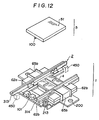
- the sixth preferred embodiment of the planar linear pulse motor of the present invention is shown in Fig. 12 in a schematic view similar to Fig. 11 which related to the fifth preferred embodiment; except that this sixth preferred embodiment of the planar linear pulse motor of the present invention includes a sliding mounting construction for the planar movable member 5, and in this Fig. 12 said planar movable member 5 is shown as lifted off from the stationary assembly 1 and from said sliding mounting construction for the convenience of illustration.
- Fig. 13 shows an exploded view of this sixth preferred embodiment planar linear pulse motor
- Fig. 14 is a schematic plan view showing an exemplary application of said sixth preferred embodiment to a floppy disk drive of a word processor or a personal computer or the like.
- parts and gaps and spaces and so on which correspond to analogous parts and gaps and spaces and so on of the previously described preferred embodiments are denoted by reference numerals like to those utilized in the figures relating to said previously described preferred embodiments.
- said sixth preferred embodiment of the planar linear pulse motor of the present invention as shown in exploded perspective view in Fig. 13, as before comprises a stationary assembly 1 and a planar movable member 5, slidably mounted with respect to the stationary assembly 1 as shown by the arrow "A" in the figures.
- the stationary assembly 1 as best seen in the exploded view thereof presented in Fig. 13, comprises a permanent magnet 2 which is shaped as a rectangular prism, with as before magnetic poles on its opposite side surfaces which are different in polarity but are the same along each said side surface.
- the permanent magnet 2 extends in the direction of sliding motion of the planar movable member 5.
- Each of the magnetic core members 31a and 31b of the previous embodiments is structured as an assembly comprising two yoke members and a coil core: in detail, the magnetic core assembly 31a is again generally shaped like a letter "C”, and comprises a first yoke member 64a, a second yoke member 64b, and a coil core 62a. Similarly, the other magnetic core assembly 31b is again generally shaped like a letter "C”, and comprises a third yoke member 64c, a fourth yoke member 64d, and a coil core 62b.
- the inner end portions designated as 39a through 39d in the figures of these magnetic core assemblies 31a and 31b are applied against, i.e. are fixed in direct contact with, the left and the right side surfaces in the figures of the permanent magnet 2.
- a coil 63a is wound around a spool 65a fitted over the coil core 62a of the the magnetic core assembly 31a, while similarly a coil 63b is wound around a spool 65b fitted over the coil core 62b of the other magnetic core assembly 31b.
- a magnetic pole plate member 4 is provided, like to the magnetic pole plate member 4 of the first preferred embodiment, fixed, as for example by being bonded, across the upper surfaces in the figure of the end portions 39a through 39d of the yoke members 64a through 64d of the magnetic core assemblies 31a and 31b, so as to be securely held relatively closely to said upper surfaces of said end portions 39a through 39d, so as to allow relatively easy passage of magnetic flux between itself and them.
- the upper surfaces of this magnetic pole plate member 4 is formed with four magnetic pole teeth portions 42a through 42d, each of which as before is formed with a series of magnetic pole teeth 42, with the phases thereof differing by a phase difference of one quarter of the pitch of a series of teeth 51 which are formed on the planar movable member 5, as before.
- This planar movable member 5 is slidably mounted, by a linear bearing type construction which will be described shortly, so as to be movable with respect to the stationary assembly 1 to and fro in the direction shown by an arrow "A" in the figures, and so that the teeth series 51 on its lower surface opposes the magnetic pole teeth on the magnetic pole teeth portions 42a through 42d with a relatively small gap, typically about 50 microns, being left therebetween.
- this sixth preferred embodiment of the planar linear pulse motor of the present invention with regard to driving the planar movable member 5 to and fro with respect to the stationary assembly 1 according to supply of electrical energy to the coils 65a and 65b in one or the other direction is isomorphic to the functioning of the first preferred embodiment, and hence will not be further discussed herein in view of the desirability of brevity of explanation.
- the permanent magnet 2 and these four yoke members 64a through 64d are together mounted to a base designated in the figures as 200, which may for example be formed of a pressed plate.
- this base member 200 is generally rectangular in shape, and has four walls designated as 201, 202, 203, and 204 extending upwards from it and defining a generally rectangular shape, said walls 201, 202, 203, and 204 being formed by pulling up tab shaped cutaway portions of said base member 200.
- the permanent magnet 2 is fixed to the base member 200 in a central position thereon, and then the paired yoke members 64a through 64d are set into place two on either side of said permanent magnet 2, between the sides of said permanent magnet 2 and the corresponding one of the walls 201 and 202, and clamped in the longitudinal, direction by the walls 203 and 204.
- said yoke members 64a through 64d are securely and positively held in predetermined positions by the provision of these walls 201, 202, 203, and 204 as surrounding them.
- the magnetic pole plate member 4 is secured over the yoke members 64a through 64d as already explained.
- the base member 200 is further formed with two ear portions pierced with two holes 210a and 210b for location and mounting of this planar linear pulse motor as will be explained hereinafter, and with two turned up lugs 211 and 212 for mounting of a biasing spring 213, as also will be explained hereinafter.
- This shown and disclosed sixth preferred embodiment of the planar linear pulse motor of the present invention has four support walls 201, 202, 203, and 204 formed on its base member 200 as described above, but in alternative constructions various other numbers of such support walls could be utilized; and it is also possible optionally to connect one or more of said support walls to one or more of the yoke members 64a through 64d, as for example by welding, so that the rigidity of the planar linear pulse motor as a whole can be increased.
- the linear bearing type construction for mounting the planar movable member 5 to the stationary assembly 1 so that it is slidable with respect thereto to and fro in the direction shown by the arrow "A" in the figures will now be explained.
- It comprises two rail mechanisms, denoted respectively as 70 and 80 in the figures, which oppose one another on opposite sides of the stationary assembly 1.
- the rail mechanism 70 comprises a retainer member 71 formed with a cross section like a letter "L”, and thus this retainer member 71 has a horizontal floor portion 72 and a vertical wall portion 73.
- the floor portion 72 is formed with a plurality of rectangular through holes - two in the shown sixth preferred embodiment - denoted as 74, and each of said holes 74 has a roller 75 fitted in it, said rollers 75 thus being retained in position by the retainer member 71 and rolling on the upper surfaces of the yoke members 64a and 64b.
- the vertical wall portion 73 of the retainer member 71 is formed with two notches - two in the shown sixth preferred embodiment - denoted as 76, and each of said notches 76 has a ball 77 fitted in it, said balls 77 thus being retained in position by the retainer member 71.
- this rail mechanism 70 further comprises a backing rail 313 which also is formed with a cross section like a letter "L", and a vertical wall portion of said rail 313 backs up said balls 77 which therefore roll thereon.
- the other rail mechanism 80 likewise comprises a retainer member 81 formed with a cross section like a letter "L", and thus this retainer member 81 also has a horizontal floor portion 82 and a vertical wall portion 83.
- the floor portion 82 is formed with a plurality of rectangular through holes - two in the shown sixth preferred embodiment - denoted as 84, which are not visible in the figures, and each of said holes 84 has a roller 85 (not visible either) fitted in it, said rollers 85 thus being retained in position by the retainer member 81 and rolling on the upper surfaces of the yoke members 64c and 64d.
- the vertical wall portion 83 of the retainer member 81 is formed with two notches - two in the shown sixth preferred embodiment - denoted as 86, and each of said notches 86 has a ball 87 (these are not actually shown in the figure) fitted in it, said balls 87 thus being retained in position by the retainer member 81.
- this rail mechanism 80 further comprises a pressure rail 313 which also is formed with a cross section like a letter "L", and a vertical wall portion of said rail 313 backs up said balls 87 which therefore roll thereon.
- the planar movable member 5 is located between the rail mechanisms 70 and 80 and its side surfaces roll on the balls 77 and 87, while the edges of its lower surface as seen in the figure roll on the rollers 75 and 85.
- the backing rail 313 of the rail mechanism 70 is securely fixed to the upper sides of the yoke members 64a and 64b, as for example by being welded, and is somewhat longer by comparison with the pressure rail 314 of the other rail mechanism 80, which is rested on the upper sides of the other two yoke members 64a and 64b, and is biased towards the backing rail 313, i.e.
- the rollers 75 and 85 serve for precisely defining the gap (as mentioned before of about 50 microns) between the planar movable member 5 and the stationary assembly 1 and for supporting said planar movable member 5 in the vertical direction, while the balls 77 and 87 serve for locating and supporting the planar movable member 5 with regard to wobbling thereof in the horizontal direction.
- each of the retainer members 71 and 81 there are formed inwardly projecting stopper portions 78 and 88 respectively, which prevent motion of the planar movable member 5 in either direction past certain determinate extreme positions thereof by engaging with the teeth 51 formed on the underside in the figures of said planar movable member 5.
- planar linear pulse motor of the present invention is to be mounted to an apparatus, for example to a floppy disk drive of a word processor or a personal computer or the like for driving the movement of the magnetic head or heads thereof as exemplarily shown in Fig.
- the body 500 of said exemplary floppy disk drive to be provided with two positioning projections 450, so arranged that, when the head or heads denoted as 460 of said floppy disk drive are mounted to the planar movable member 5 of this planar linear pulse motor so as to be linearly driven thereby, and when the extensions 422 and 423 of the backing rail 313 of the rail mechanism 70 are positioned against said positioning projections 450 and are clamped thereto as for example by screws, the line of motion denoted as "f" of said head or heads 460 intersects the rotational axis denoted as "P" of a floppy disk 470 fitted in this floppy disk drive.
- This provides a reliable and secure means for easily positioning this planar linear pulse motor in the floppy disk drive, without any requirement for the use of a jig or the like during assembly thereof, and accordingly makes the assembly work for such a floppy disk drive much easier and reduces the overall manufacturing cost thereof.
- precision in the machining accuracy of the backing rail 313 of the rail mechanism 70 is effective both for improving the accuracy of positioning of the planar movable member 5 relative to the stationary assembly 1 and also for improving the accuracy of positioning of the planar linear pulse motor as a whole relative to the device to which it is to be fitted, thereby advantageously accomplishing two independent results at once as a result of the performance of a single act of care in manufacture.
- planar linear pulse motor After this positioning of the planar linear pulse motor as a whole relative to the device to which it is to be fitted as described above, it may then be securely fixed in place by being bolted down by bolts (not particularly shown) passed through the two holes 210a and 210b formed through the aforementioned two ear portions of said base member 200 thereof.
- a means for detecting the position of the planar movable member 5 relative to the stationary assembly 1 is provided, as will now be explained.
- a light emitting and receiving unit denoted as 101 which lies approximately, in this sixth preferred embodiment of the planar linear pulse motor of the present invention, on the mid line of the planar movable member 5 as it is slidably mounted on the stationary assembly 1.
- This light emitting and receiving unit 101 comprises a light emitting unit 103 and a light receiving unit 104 which oppose one another across a gap 102, substantially perpendicularly to the direction of motion of the planar movable member 5 relative to the stationary assembly 1.
- the light emitting unit 103 during use of this planar linear pulse motor as for example in a floppy disk drive as exemplarily illustrated in Fig. 14, emits a beam of electromagnetic radiation towards the light receiving unit 104, which, if and only if said electromagnetic radiation beam is not interrupted, receives it and generates an output electrical signal.
- the planar movable member 5 approximately in its central end edge portion in this sixth preferred embodiment, there is mounted a light interrupting plate 101 which extends in the downward direction as seen in the figure.
- this light interrupting plate 101 passes into the gap 102 and interrupts the aforementioned electromagnetic radiation beam from the light emitting unit 103 to the light receiving unit 104, thus causing the interruption of the output signal from said light receiving unit 104; but, when said planar movable member 5 is at any other position in its travel relative to said stationary assembly 1, then said light interrupting plate 101 does not pass into the gap 102 and accordingly does not interrupt the aforementioned electromagnetic radiation beam from the light emitting unit 103 to the light receiving unit 104, thus not causing the interruption of the output signal from said light receiving unit 104 and allowing said output signal to continue.
- the output signal from said light receiving unit 104 may conveniently be sent to a circuit such as a Schmitt circuit such as the one exemplarily shown in Fig. 15 for providing ON/OFF control by detecting the extreme point of the travel of said planar movable member 5.
- the exemplary constitution is illustrated in which the normal output is ON when the planar movable member 5 is at a point of its travel other than said extreme point thereof, and in which the output is OFF when said planar movable member 5 is at said extreme point of its travel; and it is possible to reverse this relationship by the use of an inversion circuit, for example.
- planar linear pulse motor as in a floppy disk drive as exemplarily illustrated in Fig. 14, with the magnetic head or heads 460 attached via a support member or members (not particularly shown) to the planar movable member 5: when said planar movable member 5 is within its normal operating range and not at said end point of its travel, then the light interrupting plate 101 does not pass into the gap 102 and accordingly does not interrupt the electromagnetic radiation beam from the light emitting unit 103 to the light receiving unit 104, thus not causing the interruption of the output signal from said light receiving unit 104 and allowing said output signal to continue.
Landscapes
- Engineering & Computer Science (AREA)
- Physics & Mathematics (AREA)
- Chemical & Material Sciences (AREA)
- Combustion & Propulsion (AREA)
- Electromagnetism (AREA)
- Power Engineering (AREA)
- Linear Motors (AREA)
- Control Of Stepping Motors (AREA)
- Reciprocating, Oscillating Or Vibrating Motors (AREA)
Claims (27)
- Un moteur linéaire à impulsions plan, comprenant un premier et un deuxième ensembles (5, 1) qui sont mobiles l'un par rapport à l'autre le long d'une ligne axiale;
ledit premier ensemble (5) comprenant un groupe de dents polaires magnétiques (51), lesdites dents polaires magnétiques étant agencées, selon un pas déterminé, dans une rangée le long d'une ligne sensiblement parallèle à ladite ligne axiale, et chacune desdites dents polaires magnétiques (51) étant allongée dans une direction sensiblement perpendiculaire à ladite ligne axiale;
et ledit deuxième ensemble (1) comprenant:
quatre groupes de dents polaires magnétiques (42a à 42d), chacun desdits groupes étant agencé, sensiblement selon ledit pas déterminé, dans une rangée le long d'une ligne sensiblement parallèle à ladite ligne axiale, les phases desdits quatre groupes de dents polaires magnétiques étant sensiblement décalées l'une par rapport à l'autre et chaque dent polaire magnétique étant allongée dans une direction sensiblement perpendiculaire à ladite ligne axiale; lesdits quatre groupes de dents polaires magnétiques (42a à 42d) de ce deuxième ensemble (1) étant sensiblement face-à-face avec ledit groupe de dents polaires magnétiques (51) dudit premier ensemble (5) dans une relation sensiblement parallèle, un intervalle relativement faible étant présent entre elles;
un aimant permanent (2) comportant, sur ses surfaces latérales, des pôles magnétiques opposés sur chaque côté de son axe longitudinal;
une paire d'éléments de noyaux magnétiques (31a, 31b), dont l'un est contigu à l'une desdites surfaces latérales polaires magnétiques dudit aimant permanent (2) et dont l'autre est contigu à l'autre desdites surfaces latérales polaires magnétiques dudit aimant permanent, chacun desdits éléments comprenant deux surfaces polaires contiguës à deux desdits groupes de dents polaires magnétiques (42a à 42d) de ce deuxième ensemble (1);
et:
pour chacun desdits éléments de noyaux magnétiques, un moyen (32a, 32b) destiné à y induire un flux magnétique. - Un moteur linéaire à impulsions plan selon la revendication 1, dans lequel les phases desdits quatre groupes de dents polaires magnétiques (42a à 42d) dudit deuxième ensemble (1) sont décalées l'une par rapport à l'autre d'une quantité qui est sensiblement égale à un quart dudit pas déterminé.
- Un moteur linéaire à impulsions plan selon la revendication 1, dans lequel lesdits quatre groupes de dents polaires magnétiques (42a à 42d) dudit deuxième ensemble (1) sont formés en tant que parties d'un élément (4) de dents polaires magnétiques d'un seul tenant.
- Un moteur linéaire à impulsions plan selon la revendication 3, dans lequel ledit organe (4) de dents polaires magnétiques comprend des parties de bandes (44) qui assemblent entre eux d'un seul tenant lesdits quatre groupes de dents polaires magnétiques (42a à 42d).
- Un moteur linéaire à impulsions plan selon la revendication 4, dans lequel ledit élément (4) de dents polaires magnétiques est d'une forme généralement rectangulaire creuse, lesdits quatre groupes de dents polaires magnétiques (42a à 42d) étant situés à ses quatre coins et lesdites parties de bandes (44) étant assemblées d'un seul tenant sur lesdits quatre groupes de dents polaires magnétiques et s'étendant le long de ses bords.
- Un moteur linéaire à impulsions plan selon la revendication 1 dans lequel lesdits deux éléments de noyaux magnétiques (31a, 31b) sont généralement en forme de lettre "C".
- Un moteur linéaire à impulsions plan selon la revendication 1 ou la revendication 6, dans lequel lesdits deux éléments de noyaux magnétiques (31a, 31b) et ledit aimant permanent (2) sont généralement coplanaires.
- Un moteur linéaire à impulsions plan selon la revendication 1 ou la revendication 6, dans lequel lesdits quatre groupes de dents polaires magnétiques (42a à 42d) dudit deuxième ensemble (1) sont fixés par paires sur lesdits deux éléments de noyaux magnétiques (31a, 31b) généralement à côté de l'emplacement où lesdits deux éléments de noyaux magnétiques sont fixés sur lesdites surfaces latérales polaires magnétiques dudit aimant permanent (2).
- Un moteur linéaire à impulsions plan selon la revendication 1, dans lequel ledit aimant permanent (2) s'étend sensiblement en parallèle à ladite ligne axiale.
- Un moteur linéaire à impulsions plan selon la revendication 1, dans lequel ledit aimant permanent (2) s'étend de façon sensiblement perpendiculaire à ladite ligne axiale.
- Un moteur linéaire à impulsions plan selon la revendication 1, dans lequel ledit moyen destiné à induire un champ magnétique dans chacun desdits éléments de noyaux magnétiques comprend une bobine (32a, 32b) enroulée autour de la partie centrale dudit élément de noyau magnétique (31a, 31b).
- Un moteur linéaire à impulsions plan selon la revendication 1, dans lequel ledit moyen destiné à induire un champ magnétique dans chacun desdits éléments de noyaux magnétiques (31a, 31b) comprend deux bobines (32a, 32b), l'une étant enroulée autour d'une partie dudit élément de noyau magnétique voisine de l'une de ses dites surfaces polaires contiguë à l'un desdits groupes de dents polaires magnétiques (42a à 42d) dudit deuxième ensemble (1) correspondant à cet élément de noyau magnétique, et l'autre étant enroulée autour d'une partie dudit élément de noyau magnétique voisine de l'autre desdites surfaces polaires contiguë à l'autre desdits groupes de dents polaires magnétiques dudit deuxième ensemble correspondant à cet élément de noyau magnétique.
- Un moteur linéaire à impulsions plan selon la revendication 1, dans lequel ladite paire d'éléments de noyaux magnétiques (31a, 31b) et lesdits quatre groupes de dents polaires magnétiques (42a à 42d) dudit deuxième ensemble (1) sont tous formés en tant que parties d'un élément (20) d'un seul tenant.
- Un moteur linéaire à impulsions plan selon la revendication 13, dans lequel ledit élément (20) d'un seul tenant est en un métal magnétique.
- Un moteur linéaire à impulsions plan selon la revendication 13, dans lequel ledit aimant permanent (2) dudit deuxième ensemble (1) est ajusté à frottement dur dans une fente (21) ménagée dans ledit élément (20) d'un seul tenant.
- Un moteur linéaire à impulsions plan selon la revendication 13, dans lequel ledit aimant permanent (2) dudit deuxième ensemble (1) est moulé dans une fente (21) ménagée dans ledit élément (20) d'un seul tenant.
- Un moteur linéaire à impulsions plan selon la revendication 1, dans lequel ledit deuxième ensemble (1) comprend un élément de base (200) et une paroi de support (201, 202, 203, 204) s'élevant à partir de celui-ci, lesdits quatre groupes de dents polaires magnétiques (42a à 42d) étant supportés sur chaque côté dudit aimant permanent (2) sur ladite base (200) contre ladite paroi de support.
- Un moteur linéaire à impulsions plan selon la revendication 17, dans lequel ladite paroi de support (201 à 204) est formée d'un seul tenant avec ladite base (200) sous forme d'une partie de pattes de celle-ci recourbées vers le haut.
- Un moteur linéaire à impulsions plan selon la revendication 17, dans lequel ladite base (200) comporte un prolongement adapté au montage dudit moteur linéaire à impulsions plan sur un autre objet.
- Un moteur linéaire à impulsions plan selon la revendication 17, comprenant en outre un moyen (213) destiné à solliciter lesdits quatre groupes de dents polaires magnétiques (42a à 42d) et ledit aimant permanent (2) contre ladite paroi de support.
- Un moteur linéaire à impulsions plan selon la revendication 20, dans lequel ledit moyen de sollicitation (213) est un ressort.
- Un moteur linéaire à impulsions plan selon la revendication 21, dans lequel ladite base (200) comporte une partie de montage de ressort pour supporter ledit ressort (213).
- Un moteur linéaire à impulsions plan selon la revendication 1, comprenant en outre un moyen destiné à supporter mutuellement ledit premier (5) et ledit deuxième (1) ensembles l'un par rapport à l'autre de façon qu'ils soient mobiles l'un par rapport à l'autre le long de ladite ligne axiale, dans lequel ledit moyen de support comprend en outre un moyen pour positionner ledit moteur linéaire à impulsions plan par rapport à un élément sur lequel il doit être monté.
- Un moteur linéaire à impulsions plan selon la revendication 23, dans lequel ledit moyen de support comprend un rail (70) le long duquel coulisse ledit premier ensemble (5); ledit moyen de positionnement comprenant un prolongement (422, 423) dudit rail.
- Un moteur linéaire à impulsions plan selon la revendication 24, dans lequel ledit rail (70) est prolongé à ses deux extrémités qui sont toutes deux comprises dans ledit moyen de positionnement.
- Un moteur linéaire à impulsions plan selon la revendication 1, comprenant en outre un moyen pour détecter la position du premier ensemble (5) par rapport audit deuxième ensemble (1).
- Un moteur linéaire à impulsions plan selon la revendication 26, dans lequel ledit moyen de détection de position comprend: un élément (101) formant écran contre un rayonnement électromagnétique, monté sur ledit premier ensemble (5); et un élément (103) émettant un rayonnement électromagnétique et un élément (104) recevant un rayonnement électromagnétique montés sur ledit deuxième ensemble (1); ledit élément (101) formant écran à un rayonnement électromagnétique interrompant, lorsque ledit premier ensemble (5) est dans une position déterminée par rapport audit deuxième ensemble (1), un rayonnement électromagnétique passant depuis ledit élément (103) émettant un rayonnement électromagnétique vers ledit élément (104) recevant un rayonnement électromagnétique, mais ledit élément formant écran à un rayonnement électromagnétique n'interrompant donc pas, lorsqu'en revanche ledit premier ensemble n'est pas dans ladite position déterminée par rapport audit deuxième ensemble, un rayonnement électromagnétique passant depuis ledit élément émettant un rayonnement électromagnétique vers ledit élément recevant un rayonnement électromagnétique.
Priority Applications (1)
| Application Number | Priority Date | Filing Date | Title |
|---|---|---|---|
| AT86116569T ATE64499T1 (de) | 1986-01-14 | 1986-11-28 | Planarer linear-impulsmotor. |
Applications Claiming Priority (2)
| Application Number | Priority Date | Filing Date | Title |
|---|---|---|---|
| JP5655/86 | 1986-01-14 | ||
| JP61005655A JPH0687651B2 (ja) | 1986-01-14 | 1986-01-14 | リニアパルスモ−タ |
Publications (3)
| Publication Number | Publication Date |
|---|---|
| EP0229280A2 EP0229280A2 (fr) | 1987-07-22 |
| EP0229280A3 EP0229280A3 (en) | 1988-05-04 |
| EP0229280B1 true EP0229280B1 (fr) | 1991-06-12 |
Family
ID=11617137
Family Applications (1)
| Application Number | Title | Priority Date | Filing Date |
|---|---|---|---|
| EP86116569A Expired - Lifetime EP0229280B1 (fr) | 1986-01-14 | 1986-11-28 | Moteur linéaire à structure plane pour impulsions |
Country Status (5)
| Country | Link |
|---|---|
| US (1) | US4860183A (fr) |
| EP (1) | EP0229280B1 (fr) |
| JP (1) | JPH0687651B2 (fr) |
| AT (1) | ATE64499T1 (fr) |
| DE (1) | DE3679798D1 (fr) |
Families Citing this family (17)
| Publication number | Priority date | Publication date | Assignee | Title |
|---|---|---|---|---|
| GB2300312B (en) * | 1995-04-27 | 1999-11-24 | Blum Gmbh | A polyphase transverse flux machine |
| US5965962A (en) * | 1998-02-20 | 1999-10-12 | Northern Magnetics, Inc. | Linear stepper motor |
| JP3894297B2 (ja) * | 2001-02-28 | 2007-03-14 | 富士電機機器制御株式会社 | リニアアクチュエータ |
| US10020716B2 (en) * | 2010-03-31 | 2018-07-10 | The Boeing Company | Transverse flux induction motor with passive braking system |
| US9956969B2 (en) * | 2015-04-30 | 2018-05-01 | The Boeing Company | Brake device |
| US10714985B2 (en) | 2017-10-11 | 2020-07-14 | Spark Connected LLC | Wireless power transfer system and method |
| US11509169B2 (en) | 2019-02-13 | 2022-11-22 | Spark Connected LLC | Sub-surface wireless charging |
| US11152823B2 (en) | 2019-04-01 | 2021-10-19 | Spark Connected LLC | Translation unit for wireless power transfer |
| US11394242B2 (en) | 2019-09-12 | 2022-07-19 | Spark Connected LLC | Wireless power transfer in-band communication circuit and method |
| US11515739B2 (en) | 2020-02-14 | 2022-11-29 | Spark Connected LLC | FOD and wireless power transfer calibration |
| US12068631B2 (en) | 2020-04-13 | 2024-08-20 | Spark Connected LLC | Alignment method for sub-surface wireless charger |
| US12053055B2 (en) | 2020-05-15 | 2024-08-06 | Spark Connected LLC | Dual function wireless power and thermal receiver |
| US11888331B2 (en) | 2020-07-01 | 2024-01-30 | Spark Connected LLC | Sub-surface wireless charging and associated method |
| US11855463B2 (en) | 2020-12-04 | 2023-12-26 | Spark Connected LLC | Wireless power transmission to a mobile device |
| US12500451B2 (en) | 2021-05-20 | 2025-12-16 | Spark Connected LLC | Wireless power transmitter and receiver |
| US12562600B2 (en) | 2021-07-20 | 2026-02-24 | Spark Connected LLC | Foreign object detection testing for wireless chargers |
| CN114172343B (zh) * | 2021-12-10 | 2023-03-24 | 合肥工业大学 | 基于气隙磁通密度波形正弦化设计的混合式磁极直线电机 |
Family Cites Families (6)
| Publication number | Priority date | Publication date | Assignee | Title |
|---|---|---|---|---|
| JPS5746670A (en) * | 1980-09-04 | 1982-03-17 | Matsushita Electric Ind Co Ltd | Brushless linear servo motor |
| US4504750A (en) * | 1982-04-21 | 1985-03-12 | Matsushita Electric Industrial Co., Ltd. | Linear motor |
| US4578622A (en) * | 1982-10-26 | 1986-03-25 | Shinko Electric Co., Ltd. | Linear pulse motor |
| JPS60113652A (ja) * | 1983-11-22 | 1985-06-20 | Shinko Electric Co Ltd | リニアパルスモ−タ |
| JPS60241767A (ja) * | 1984-05-15 | 1985-11-30 | Shinko Electric Co Ltd | リニアパルスモ−タ |
| JPS60237853A (ja) * | 1984-05-10 | 1985-11-26 | Shinko Electric Co Ltd | リニアパルスモ−タ |
-
1986
- 1986-01-14 JP JP61005655A patent/JPH0687651B2/ja not_active Expired - Fee Related
- 1986-11-28 EP EP86116569A patent/EP0229280B1/fr not_active Expired - Lifetime
- 1986-11-28 AT AT86116569T patent/ATE64499T1/de not_active IP Right Cessation
- 1986-11-28 DE DE8686116569T patent/DE3679798D1/de not_active Expired - Fee Related
- 1986-12-01 US US06/936,242 patent/US4860183A/en not_active Expired - Fee Related
Also Published As
| Publication number | Publication date |
|---|---|
| EP0229280A2 (fr) | 1987-07-22 |
| EP0229280A3 (en) | 1988-05-04 |
| JPH0687651B2 (ja) | 1994-11-02 |
| US4860183A (en) | 1989-08-22 |
| DE3679798D1 (de) | 1991-07-18 |
| JPS62166763A (ja) | 1987-07-23 |
| ATE64499T1 (de) | 1991-06-15 |
Similar Documents
| Publication | Publication Date | Title |
|---|---|---|
| EP0229280B1 (fr) | Moteur linéaire à structure plane pour impulsions | |
| US4318038A (en) | Moving-coil linear motor | |
| EP1193847B1 (fr) | Glissière à moteur linéaire avec bobine mobile integrée | |
| JPH08275500A (ja) | リニアモータ | |
| US5588312A (en) | Driving apparatus for needles of knitting machine | |
| US5038062A (en) | Swing-arm type linear d.c. brushless motor | |
| WO2016103946A1 (fr) | Moteur linéaire | |
| JPH0265656A (ja) | コアレスリニアモーター | |
| US7453172B2 (en) | Linear slide apparatus | |
| US20090051227A1 (en) | Linear motor | |
| JPH07170712A (ja) | アクチュエータ | |
| CA1284167C (fr) | Moteur pulse lineaire planar | |
| JP2002096233A (ja) | リニアスライダ | |
| US20090026847A1 (en) | Linear motor | |
| JP4074170B2 (ja) | リニアモータを用いた送り装置 | |
| JP3515790B2 (ja) | 情報記録再生装置における光学ヘッド駆動装置 | |
| JPH08275495A (ja) | リニアモータ | |
| JP4522674B2 (ja) | 小型スライド装置 | |
| JPH08275497A (ja) | リニアモータ | |
| JP2789543B2 (ja) | Xyテーブル | |
| JPS6314584B2 (fr) | ||
| JPH02307356A (ja) | リニアパルスモータ | |
| JPS60167669A (ja) | リニアモ−タ装置 | |
| JPH0564413A (ja) | リニアアクチユエータ | |
| JPH0312523Y2 (fr) |
Legal Events
| Date | Code | Title | Description |
|---|---|---|---|
| PUAI | Public reference made under article 153(3) epc to a published international application that has entered the european phase |
Free format text: ORIGINAL CODE: 0009012 |
|
| 17P | Request for examination filed |
Effective date: 19861128 |
|
| AK | Designated contracting states |
Kind code of ref document: A2 Designated state(s): AT BE CH DE ES FR GB GR IT LI LU NL SE |
|
| RIN1 | Information on inventor provided before grant (corrected) |
Inventor name: MAEDA, TETSUO Inventor name: OHTA, HIROFUMI Inventor name: INAZUMI, HIROKUNI |
|
| PUAL | Search report despatched |
Free format text: ORIGINAL CODE: 0009013 |
|
| AK | Designated contracting states |
Kind code of ref document: A3 Designated state(s): AT BE CH DE ES FR GB GR IT LI LU NL SE |
|
| 17Q | First examination report despatched |
Effective date: 19900801 |
|
| GRAA | (expected) grant |
Free format text: ORIGINAL CODE: 0009210 |
|
| AK | Designated contracting states |
Kind code of ref document: B1 Designated state(s): AT BE CH DE ES FR GB GR IT LI LU NL SE |
|
| PG25 | Lapsed in a contracting state [announced via postgrant information from national office to epo] |
Ref country code: IT Free format text: LAPSE BECAUSE OF FAILURE TO SUBMIT A TRANSLATION OF THE DESCRIPTION OR TO PAY THE FEE WITHIN THE PRE;WARNING: LAPSES OF ITALIAN PATENTS WITH EFFECTIVE DATE BEFORE 2007 MAY HAVE OCCURRED AT ANY TIME BEFORE 2007. THE CORRECT EFFECTIVE DATE MAY BE DIFFERENT FROM THE ONE RECORDED.SCRIBED TIME-LIMIT Effective date: 19910612 Ref country code: AT Effective date: 19910612 Ref country code: LI Effective date: 19910612 Ref country code: GR Free format text: LAPSE BECAUSE OF FAILURE TO SUBMIT A TRANSLATION OF THE DESCRIPTION OR TO PAY THE FEE WITHIN THE PRESCRIBED TIME-LIMIT Effective date: 19910612 Ref country code: CH Effective date: 19910612 Ref country code: SE Effective date: 19910612 Ref country code: BE Effective date: 19910612 Ref country code: NL Effective date: 19910612 |
|
| REF | Corresponds to: |
Ref document number: 64499 Country of ref document: AT Date of ref document: 19910615 Kind code of ref document: T |
|
| REF | Corresponds to: |
Ref document number: 3679798 Country of ref document: DE Date of ref document: 19910718 |
|
| ET | Fr: translation filed | ||
| REG | Reference to a national code |
Ref country code: CH Ref legal event code: PL |
|
| PG25 | Lapsed in a contracting state [announced via postgrant information from national office to epo] |
Ref country code: ES Free format text: LAPSE BECAUSE OF FAILURE TO SUBMIT A TRANSLATION OF THE DESCRIPTION OR TO PAY THE FEE WITHIN THE PRESCRIBED TIME-LIMIT Effective date: 19910923 |
|
| PGFP | Annual fee paid to national office [announced via postgrant information from national office to epo] |
Ref country code: FR Payment date: 19911106 Year of fee payment: 6 |
|
| NLV1 | Nl: lapsed or annulled due to failure to fulfill the requirements of art. 29p and 29m of the patents act | ||
| PGFP | Annual fee paid to national office [announced via postgrant information from national office to epo] |
Ref country code: DE Payment date: 19911129 Year of fee payment: 6 |
|
| PG25 | Lapsed in a contracting state [announced via postgrant information from national office to epo] |
Ref country code: LU Free format text: LAPSE BECAUSE OF NON-PAYMENT OF DUE FEES Effective date: 19911130 |
|
| PLBE | No opposition filed within time limit |
Free format text: ORIGINAL CODE: 0009261 |
|
| STAA | Information on the status of an ep patent application or granted ep patent |
Free format text: STATUS: NO OPPOSITION FILED WITHIN TIME LIMIT |
|
| 26N | No opposition filed | ||
| PG25 | Lapsed in a contracting state [announced via postgrant information from national office to epo] |
Ref country code: FR Effective date: 19930730 |
|
| PG25 | Lapsed in a contracting state [announced via postgrant information from national office to epo] |
Ref country code: DE Effective date: 19930803 |
|
| REG | Reference to a national code |
Ref country code: FR Ref legal event code: ST |
|
| REG | Reference to a national code |
Ref country code: GB Ref legal event code: IF02 |
|
| PGFP | Annual fee paid to national office [announced via postgrant information from national office to epo] |
Ref country code: GB Payment date: 20021011 Year of fee payment: 17 |
|
| PG25 | Lapsed in a contracting state [announced via postgrant information from national office to epo] |
Ref country code: GB Free format text: LAPSE BECAUSE OF NON-PAYMENT OF DUE FEES Effective date: 20031128 |
|
| GBPC | Gb: european patent ceased through non-payment of renewal fee |
Effective date: 20031128 |