EP0229401A1 - Feldberegnungsgerät - Google Patents
Feldberegnungsgerät Download PDFInfo
- Publication number
- EP0229401A1 EP0229401A1 EP86200051A EP86200051A EP0229401A1 EP 0229401 A1 EP0229401 A1 EP 0229401A1 EP 86200051 A EP86200051 A EP 86200051A EP 86200051 A EP86200051 A EP 86200051A EP 0229401 A1 EP0229401 A1 EP 0229401A1
- Authority
- EP
- European Patent Office
- Prior art keywords
- piston
- cylinder
- valve
- pressure
- reel
- Prior art date
- Legal status (The legal status is an assumption and is not a legal conclusion. Google has not performed a legal analysis and makes no representation as to the accuracy of the status listed.)
- Ceased
Links
Images


Classifications
-
- F—MECHANICAL ENGINEERING; LIGHTING; HEATING; WEAPONS; BLASTING
- F03—MACHINES OR ENGINES FOR LIQUIDS; WIND, SPRING, OR WEIGHT MOTORS; PRODUCING MECHANICAL POWER OR A REACTIVE PROPULSIVE THRUST, NOT OTHERWISE PROVIDED FOR
- F03C—POSITIVE-DISPLACEMENT ENGINES DRIVEN BY LIQUIDS
- F03C1/00—Reciprocating-piston liquid engines
- F03C1/007—Reciprocating-piston liquid engines with single cylinder, double-acting piston
- F03C1/0073—Reciprocating-piston liquid engines with single cylinder, double-acting piston one side of the double-acting piston being always under the influence of the liquid under pressure
- F03C1/0076—Reciprocating-piston liquid engines with single cylinder, double-acting piston one side of the double-acting piston being always under the influence of the liquid under pressure the liquid under pressure being continuously delivered to one cylinder chamber through a valve in the piston for actuating the return stroke
-
- A—HUMAN NECESSITIES
- A01—AGRICULTURE; FORESTRY; ANIMAL HUSBANDRY; HUNTING; TRAPPING; FISHING
- A01G—HORTICULTURE; CULTIVATION OF VEGETABLES, FLOWERS, RICE, FRUIT, VINES, HOPS OR SEAWEED; FORESTRY; WATERING
- A01G25/00—Watering gardens, fields, sports grounds or the like
- A01G25/09—Watering arrangements making use of movable installations on wheels or the like
- A01G25/095—Watering arrangements making use of movable installations on wheels or the like winch-driven
-
- F—MECHANICAL ENGINEERING; LIGHTING; HEATING; WEAPONS; BLASTING
- F04—POSITIVE - DISPLACEMENT MACHINES FOR LIQUIDS; PUMPS FOR LIQUIDS OR ELASTIC FLUIDS
- F04B—POSITIVE-DISPLACEMENT MACHINES FOR LIQUIDS; PUMPS
- F04B9/00—Piston machines or pumps characterised by the driving or driven means to or from their working members
- F04B9/08—Piston machines or pumps characterised by the driving or driven means to or from their working members the means being fluid
- F04B9/10—Piston machines or pumps characterised by the driving or driven means to or from their working members the means being fluid the fluid being liquid
- F04B9/103—Piston machines or pumps characterised by the driving or driven means to or from their working members the means being fluid the fluid being liquid having only one pumping chamber
- F04B9/105—Piston machines or pumps characterised by the driving or driven means to or from their working members the means being fluid the fluid being liquid having only one pumping chamber reciprocating movement of the pumping member being obtained by a double-acting liquid motor
- F04B9/1053—Piston machines or pumps characterised by the driving or driven means to or from their working members the means being fluid the fluid being liquid having only one pumping chamber reciprocating movement of the pumping member being obtained by a double-acting liquid motor one side of the double-acting liquid motor being always under the influence of the liquid under pressure
Definitions
- the invention relates to an overhead irriqation device as defined in the heading of claim 1.
- Such an irriaa- tion device is used for irrigating a crop with water or manure.
- the liquid is supplied by a pump apparatus set up at a distance.
- the free end of the hose is connected with a spray device.
- the hose is wholly or partially unreeled and the spray device is arranged at a distance from the overhead irrigation device.
- the reel is slowly rotated by the rotary drive mechanism, whereby the hose is reeled in evenly so that an extensive area is automatically irrigated.
- the purpose of the invention is to provide a device of the kind set forth above in which the motor operates at .a high level of efficiency.
- a preferred embodiment is obtained using the characteristic of claim 2.
- the valve at the end of the active stroke opens in a reliable manner when the step characterizing claim 3 is applied.
- the helical springs are tensioned until the valve disc is lifted from the seat counter to the liquid pressure.
- the pressure on the valve disc decreases so that it is moved progressively away from the valve seat through the spring pressure.
- the duration of the backward, slack stroke of the piston can be determined in a simple manner by a suitable choice of restriction.
- oil is fed via the non-return valve virtually without loss of power.
- the power supplied by the motor is dependent on the momentary force necessary for the rotation of the reel.
- the pressure applied by the liquid on the valve disc is thus likewise variable.
- Using the step in claim 6 achieves that at all times, at the end of the active stroke, the same equilibrium of forces acts on the valve disc, so that valve release takes place in a reliable manner.
- a favourable embodiment of the pressure discharge device is that in the embodiment according to claim 7.
- the retracting speed of the hose is constant, irrespective of the momentary reel diameter of the hose.
- the retracting speed would increase at a constant speed of rotation.
- the cycle time of the motor is increased and the drive speed of the reel thus reduced.
- Overhead irrigation device 1 is provided with a drive mechanism 6 for reeling in hose 4 during the operation of the device.
- a drive mechanism 6 for reeling in hose 4 during the operation of the device.
- reeling in of hose 4 spray device 10 is pulled towards irrigation device 1, whereby a rectangular area is evenly irrigated automatically.
- Drive mechanism 6 comprises a motor 7 which absorbs drive energy from the liquid fed under pressure through line 5. As a result it is not necessary to use for example a separate diesel motor for driving of the reel.
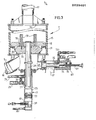
- motor 7 comprises a cylinder 15 which is accomodated axially in feed line 5. That is to say; the liquid supplied through feed line 5 flows axially through cylinder 15. The liquid is fed through the inlet 16 and leaves cylinder 15 through the outlet 17 on the upper side.
- a piston I8 which, sealed by means of a sealing 19, is guided slidably in the cylinder.
- Piston 18 is connected to a piston rod 20 which is coupled with the reel drive gear to be described later.
- the piston comprises a valve seat 33 on the underside which co-operates with the edge of a valve disc 30, which is guided slidably around the piston rod.
- piston 18 is located in the start position, in which valve disc 30 makes sealing contact with valve seat 33.
- Piston 18 with piston rod 20 is pushed upwards in the cylinder 15 by the water fed via inlet 16 under the piston. Through the pressure of the water valve disc 30 remains in sealing contact with valve seat 33.
- power is extracted from piston rod 20 by the reel drive device.
- piston 18 Because of the water pressure acting on the section of piston rod 20, the piston is then moved back again from the position shown in Fig. 4 to that shown in Fig. 3. At the end of this movement piston 18 again comes with its valve seat 33 into contact with valve disc 30, whereby the valve closes and the cycle described is repeated.
- piston rod 20 of motor 7 is coupled with a hydraulic reciprocating pump 21.
- This comprises a pump cylinder 23 and a pump piston 22 arranged at the end of piston rod 20.
- connection for suction pipe 25 is arranged in pump cylinder 23 at an interval under the connection for pressure pipe 24, and between these pipes a bypass pipe 26 is arranged.
- Fig. 4 shows, the spaces in pump cylinder 23 above and below pump piston 22 are connected to one another via bypass pipe 26 when motor piston 18 is situated close to its end position. There is, therefore, no difference in pressure over pump piston 22.
- the pressure applied by the water on valve disc 30-in this end position is the same and slight under all operating conditions. The equilibrium of forces whereby lifting the valve occurs is therefore independent of the pressure generated during the active stroke. This results in the valve always being lifted in a reliable manner.
- the space in pump cylinder 23 under pump piston 22 is linked by means of a connection 38 with the reservoir of hydraulic oil.
- hydraulic oil is fed via connection 38 into cylinder 23 via non-return valve 39.
- non-return valve 39 closes and the hydraulic oil is displaced via restriction 40 to connection 38.
- the duration of the downward stroke can therefore be adjusted using restriction 40.
- the wind-in speed of reel 3, which is dependent on the cycle duration of the motor, can as a result be adjusted.
- the device 1 comprises for this purpose a sensing frame 44 which is connected pivotably with the frame 2 by means of a hinge 45.
- the upper edge of this frame 44 lies against the hose wound in on reel 3.
- sensing frame 44 tilts anti-clockwise as seen in Fig. 2.
- a rod 50 is connected for pivoting with an arm 46 which moves firmly with frame 44.
- the other end of rod 50 grips on a lever 47 coupled for pivoting through hinge 42 with frame 2.
- the other end of lever 47 relative to hinge 49 is again coupled for pivoting with a rod 48. which is coupled with the tapered pin of restriction 40.
- Fig. 5 shows the hydraulic diagram of device 1.
- bypass pipe 26 is arranged to ensure that the last part of the active stroke of the reciprocating pump takes place without pressure in view of the action of the motor.
- non-return valve 27 which is accomodated in suction pipe 25 between the cylinder and the connection for bypass pipe 26 is achieved that during the slack return stroke, directly from the uppermost point, the influence of the damping obtained with restriction 40 becomes active.
- Pressure pipe 24 is connected via a pressure controlled two-way valve 55 with drive cylinder 61.
- a pressure controlled two-way valve is in itself known and need not therefore be described at length.
- a pressure piece 62 which can come to grip on a part of reel 3 in the form of a ratchet wheel 63.
- Onto this ratchet wheel 63 also grips a ratched 64 connected for pivoting with the frame of the device, which ratchet allows rotation of reel 3 in the direction of arrow 65, but prevents rotation in the opposite direction.
- reel 3 is rotated over one or more "teeth" of ratchet wheel 63 after which, during the return stroke of cylinder 61, reel 3 is held in place by ratchet 64. In this way the reciprocating movement of pressure piece 62 of drive cylinder 61 is converted into a stepwise rotating movement of reel 3.
- valve 55 In the pressure and return pipes connected to valve 55 are accomodated quick action couplings 58 and 57 respectively, which are in themselves known. At the point of these couplings 58,57 the drive system for the reel can be disengaged from reciprocating pump 21 and an hydraulic pump driven for example by a tractor can be connected up. In this way reel 3 can be wound up quickly without irrigation taking place.
- the device 1 according to the invention is provided with a safety device which stops the irrigation as soon as a disturbance occurs in the reel drive.
- This safety device co-operates with the safety device arranged in the usual way in pump 9, which switches off the drive of pump 9 as soon as pump pressure falls below a determined set value.
- the safety device comprises a pressure relief valve 67 which takes the form of a piston valve and of which the piston 68 in operating conditions is under the influence of the pressure of the water for spraying fed in through connection 16.
- Piston 68 is held in the position shown closing valve 67 with the aid of the safety cylinder 60 in which oil under pressure from the hydraulic system applies an opposed force onto the rod of piston 68.
- Safety cylinder 60 is provided with a pressure conduit 70 and a discharge conduit 72 which are connected in the way shown in Fig. 5 with the pressure pipe and reservoir respectively. The oil fed under pressure via conduit 70 into cylinder 60 flows via a restriction 73 to discharge conduit 72..
- the safety device operates as follows:
- a ball valve 75 is accomodated, the ball of which is activated by the end of piston 68.
- a high oil pressure is automatically generated in the hydraulic system in the manner previously described.
- leakage via restriction 73 would assume undesirably large proportions. Since under high hydraulic oil pressure piston 68 is moved to the left, piston 68 disconnects from ball 75 which then closes off the supply of oil through line 70. An equilibrium is thus established in a known manner, whereby an acceptably small leakage flow of oil occurs through restriction 73.
- a second rod 52 is connected with the arm 46 of sensing frame 44, which rod activates ball valve 59.
- ball valve 59 In the position of sensing frame 44 corresponding with the wholly wound up hose 4, ball valve 59, which is normally closed, is opened.
- Fig. 5 shows, ball valve 59 hereby short circuits lines 70 and 72 so that no oil under pressure is fed to the safety cylinder 60, and the previously described safety device comes into operation.
- Ball valve 59 is actually connected onto the line 71 shown in Fig. 3.
- Electro-magnet 83 is controlled with the aid of a delayed action relay 87 which in activated state holds open a control contact pair.
- the relay is kept in the activated state using a pulsating supply voltage which is generated with the aid of a switch 82 controlled by ratchet 64.
- ratchet 64 moves periodically up ' and downward, whereby switch 89 is periodically closed.
- switch 89 In the closed position of switch 89 an electrical supply voltage is fed from the battery 88 to the coil of the relay and the condenser in parallel circuit with it. The circuit is thereby so dimensioned, that under normal operating conditions relay 87 remains energized by the pulsating or intermittent supply.
Landscapes
- Engineering & Computer Science (AREA)
- Mechanical Engineering (AREA)
- General Engineering & Computer Science (AREA)
- Chemical & Material Sciences (AREA)
- Combustion & Propulsion (AREA)
- Water Supply & Treatment (AREA)
- Life Sciences & Earth Sciences (AREA)
- Environmental Sciences (AREA)
- Catching Or Destruction (AREA)
Priority Applications (1)
| Application Number | Priority Date | Filing Date | Title |
|---|---|---|---|
| EP86200051A EP0229401A1 (de) | 1986-01-13 | 1986-01-13 | Feldberegnungsgerät |
Applications Claiming Priority (1)
| Application Number | Priority Date | Filing Date | Title |
|---|---|---|---|
| EP86200051A EP0229401A1 (de) | 1986-01-13 | 1986-01-13 | Feldberegnungsgerät |
Publications (1)
| Publication Number | Publication Date |
|---|---|
| EP0229401A1 true EP0229401A1 (de) | 1987-07-22 |
Family
ID=8195690
Family Applications (1)
| Application Number | Title | Priority Date | Filing Date |
|---|---|---|---|
| EP86200051A Ceased EP0229401A1 (de) | 1986-01-13 | 1986-01-13 | Feldberegnungsgerät |
Country Status (1)
| Country | Link |
|---|---|
| EP (1) | EP0229401A1 (de) |
Cited By (7)
| Publication number | Priority date | Publication date | Assignee | Title |
|---|---|---|---|---|
| CN103573539A (zh) * | 2013-11-25 | 2014-02-12 | 江苏大学 | 一种小流量卷盘式喷灌机水涡轮 |
| CN109006379A (zh) * | 2018-07-11 | 2018-12-18 | 许丽强 | 一种市政工程用公园草坪洒水设备 |
| CN110637706A (zh) * | 2019-09-25 | 2020-01-03 | 黎兴才 | 一种现代农业用排灌机械设备 |
| CN111011174A (zh) * | 2019-12-31 | 2020-04-17 | 安徽艾瑞德农业装备股份有限公司 | 一种卷盘式喷灌机 |
| CN111802232A (zh) * | 2020-07-29 | 2020-10-23 | 江苏鸣泉灌排设备有限公司 | 一种农田喷药灌溉一体化设备 |
| CN113748965A (zh) * | 2021-10-20 | 2021-12-07 | 王奇 | 一种水产养殖废水农田调节灌溉处理设备 |
| CN119999548A (zh) * | 2025-02-14 | 2025-05-16 | 内蒙古河套灌区水利发展中心 | 一种引黄滴灌用片式灌水器 |
Citations (4)
| Publication number | Priority date | Publication date | Assignee | Title |
|---|---|---|---|---|
| FR2134753A5 (de) * | 1971-04-19 | 1972-12-08 | Palma Hugo Di | |
| FR2199523A1 (de) * | 1972-09-18 | 1974-04-12 | Berrier Emile | |
| FR2326972A1 (fr) * | 1975-10-09 | 1977-05-06 | Iplex Plastic Ind Pty Ltd | Procede pour introduire des quantites mesurees de liquide dans un fluide et dispositif pour la mise en oeuvre de ce procede |
| FR2329980A2 (fr) * | 1975-11-03 | 1977-05-27 | Economics Lab | Dispositif de dosage de fluide perfectionne |
-
1986
- 1986-01-13 EP EP86200051A patent/EP0229401A1/de not_active Ceased
Patent Citations (4)
| Publication number | Priority date | Publication date | Assignee | Title |
|---|---|---|---|---|
| FR2134753A5 (de) * | 1971-04-19 | 1972-12-08 | Palma Hugo Di | |
| FR2199523A1 (de) * | 1972-09-18 | 1974-04-12 | Berrier Emile | |
| FR2326972A1 (fr) * | 1975-10-09 | 1977-05-06 | Iplex Plastic Ind Pty Ltd | Procede pour introduire des quantites mesurees de liquide dans un fluide et dispositif pour la mise en oeuvre de ce procede |
| FR2329980A2 (fr) * | 1975-11-03 | 1977-05-27 | Economics Lab | Dispositif de dosage de fluide perfectionne |
Cited By (9)
| Publication number | Priority date | Publication date | Assignee | Title |
|---|---|---|---|---|
| CN103573539A (zh) * | 2013-11-25 | 2014-02-12 | 江苏大学 | 一种小流量卷盘式喷灌机水涡轮 |
| CN103573539B (zh) * | 2013-11-25 | 2016-05-25 | 江苏大学 | 一种小流量卷盘式喷灌机水涡轮 |
| CN109006379A (zh) * | 2018-07-11 | 2018-12-18 | 许丽强 | 一种市政工程用公园草坪洒水设备 |
| CN109006379B (zh) * | 2018-07-11 | 2020-10-30 | 叶德平 | 一种市政工程用公园草坪洒水设备 |
| CN110637706A (zh) * | 2019-09-25 | 2020-01-03 | 黎兴才 | 一种现代农业用排灌机械设备 |
| CN111011174A (zh) * | 2019-12-31 | 2020-04-17 | 安徽艾瑞德农业装备股份有限公司 | 一种卷盘式喷灌机 |
| CN111802232A (zh) * | 2020-07-29 | 2020-10-23 | 江苏鸣泉灌排设备有限公司 | 一种农田喷药灌溉一体化设备 |
| CN113748965A (zh) * | 2021-10-20 | 2021-12-07 | 王奇 | 一种水产养殖废水农田调节灌溉处理设备 |
| CN119999548A (zh) * | 2025-02-14 | 2025-05-16 | 内蒙古河套灌区水利发展中心 | 一种引黄滴灌用片式灌水器 |
Similar Documents
| Publication | Publication Date | Title |
|---|---|---|
| EP0229401A1 (de) | Feldberegnungsgerät | |
| JPH0751961B2 (ja) | 液圧シリンダの行程制限装置 | |
| FR2482680A1 (fr) | Mecanisme de commande hydrostatique, notamment mecanisme de direction | |
| DE1703965C3 (de) | Schwungradenergiespeicher | |
| CN211525214U (zh) | 液压控制装置及卷管器自动收放装置 | |
| EP0313566A1 (de) | Bewegliche bewässerungsvorrichtung | |
| US3464320A (en) | Decompression system for press brakes or the like | |
| US4621379A (en) | Flushing operating means for vacuum toilet | |
| US5664539A (en) | Linear actuator fail-safe remote control | |
| FR2573151A1 (fr) | Circuit hydraulique pour organe de couplage hydrodynamique | |
| US3408901A (en) | Coordinated hydraulic motor control system and pressure coordinating valve therefor | |
| US3165277A (en) | Hydraulically operated stock reel | |
| US6142746A (en) | Pulsating valve for hydraulic rams having a liquid vessel attached thereto | |
| SU511890A1 (ru) | Гидронавесна система трактора | |
| BE1001719A6 (nl) | Debietregelsysteem voor een vertikale zuigerpomp aangedreven door windenergie. | |
| SU819261A1 (ru) | Предохранительное устройство воротшлюзА | |
| JPH0615941Y2 (ja) | 動力噴霧機のホースリール制動装置 | |
| FR2460366A1 (fr) | Barrage automatique | |
| DE633382C (de) | Elektrohydraulische Hubvorrichtung (Druecker) | |
| SU1123596A1 (ru) | Гидравлическое реле времени | |
| US4235288A (en) | Well pumping control system | |
| JPH063280B2 (ja) | 水路における送水装置 | |
| KR890001592Y1 (ko) | 역지변의 개폐상태 조절장치 | |
| SU1743482A1 (ru) | Узел водоподачи дождевальной системы | |
| JPH0741751Y2 (ja) | 空気室付きカウンタバランス弁 |
Legal Events
| Date | Code | Title | Description |
|---|---|---|---|
| PUAI | Public reference made under article 153(3) epc to a published international application that has entered the european phase |
Free format text: ORIGINAL CODE: 0009012 |
|
| AK | Designated contracting states |
Kind code of ref document: A1 Designated state(s): AT BE CH DE FR GB IT LI LU NL SE |
|
| 17P | Request for examination filed |
Effective date: 19880113 |
|
| 17Q | First examination report despatched |
Effective date: 19890206 |
|
| STAA | Information on the status of an ep patent application or granted ep patent |
Free format text: STATUS: THE APPLICATION HAS BEEN REFUSED |
|
| 18R | Application refused |
Effective date: 19901229 |