EP0229628A2 - Méthode et appareil pour le soudage automatisé - Google Patents
Méthode et appareil pour le soudage automatisé Download PDFInfo
- Publication number
- EP0229628A2 EP0229628A2 EP87100097A EP87100097A EP0229628A2 EP 0229628 A2 EP0229628 A2 EP 0229628A2 EP 87100097 A EP87100097 A EP 87100097A EP 87100097 A EP87100097 A EP 87100097A EP 0229628 A2 EP0229628 A2 EP 0229628A2
- Authority
- EP
- European Patent Office
- Prior art keywords
- welding
- arc
- point
- expectation
- electric arc
- Prior art date
- Legal status (The legal status is an assumption and is not a legal conclusion. Google has not performed a legal analysis and makes no representation as to the accuracy of the status listed.)
- Granted
Links
Images


Classifications
-
- B—PERFORMING OPERATIONS; TRANSPORTING
- B23—MACHINE TOOLS; METAL-WORKING NOT OTHERWISE PROVIDED FOR
- B23K—SOLDERING OR UNSOLDERING; WELDING; CLADDING OR PLATING BY SOLDERING OR WELDING; CUTTING BY APPLYING HEAT LOCALLY, e.g. FLAME CUTTING; WORKING BY LASER BEAM
- B23K37/00—Auxiliary devices or processes, not specially adapted for a procedure covered by only one of the other main groups of this subclass
-
- B—PERFORMING OPERATIONS; TRANSPORTING
- B23—MACHINE TOOLS; METAL-WORKING NOT OTHERWISE PROVIDED FOR
- B23K—SOLDERING OR UNSOLDERING; WELDING; CLADDING OR PLATING BY SOLDERING OR WELDING; CUTTING BY APPLYING HEAT LOCALLY, e.g. FLAME CUTTING; WORKING BY LASER BEAM
- B23K9/00—Arc welding or cutting
- B23K9/06—Arrangements or circuits for starting the arc, e.g. by generating ignition voltage, or for stabilising the arc
- B23K9/067—Starting the arc
-
- G—PHYSICS
- G05—CONTROLLING; REGULATING
- G05B—CONTROL OR REGULATING SYSTEMS IN GENERAL; FUNCTIONAL ELEMENTS OF SUCH SYSTEMS; MONITORING OR TESTING ARRANGEMENTS FOR SUCH SYSTEMS OR ELEMENTS
- G05B19/00—Program-control systems
- G05B19/02—Program-control systems electric
- G05B19/18—Numerical control [NC], i.e. automatically operating machines, in particular machine tools, e.g. in a manufacturing environment, so as to execute positioning, movement or co-ordinated operations by means of program data in numerical form
- G05B19/406—Numerical control [NC], i.e. automatically operating machines, in particular machine tools, e.g. in a manufacturing environment, so as to execute positioning, movement or co-ordinated operations by means of program data in numerical form characterised by monitoring or safety
- G05B19/4067—Restoring data or position after power failure or other interruption
Definitions
- the present invention relates to a method and apparatus for automatic welding which have means for causing a welding torch to progress along a welding expectation line. More particularly, it provides a measure against a situation in which an electric arc does not strike at a welding start expectation point.
- the principal object of the present invention is to provide a method and apparatus for automatically welding the whole section of a continuous welding expectation line.
- Another object of the present invention is to provide an apparatus in which, when an electric arc does not appear, operations for striking the electric arc are automatically executed a plurality of numbers of times at the different positions of an expected welding line on a workpiece.
- Another object of the present invention is to provide an apparatus which automatically stores the number of times of failing to strike an electric arc in spite of operations for striking the electric arc.
- the present invention utilizes means for causing a welding torch for electric arc welding to progress from a welding start expectation point on a workpiece and along a welding expectation line whose start point is the welding start expectation point.
- This means is, for example, a robot proper or a program set in a control panel for controlling the robot proper.
- means is comprised for executing arc starts with a welding wire held in contact with or in proximity to the workpiece in the course of the progression of the welding torch. The execution is repeated until an electric arc is actually struck, but the welding should better be judged impossible when the electric arc does not strike in spite of the repeated execution in a prescribed number of times.
- means is comprised for causing the welding torch to retrogress from the arc start point to the welding start expectation point while the electric arc is kept.
- This means is also the robot proper or a program in the control panel for controlling the robot proper, but it differs from the foregoing in that the program for moving the welding torch backward is executed instead of the program for moving the same forward.
- means is comprised for causing the welding torch to progress again from the welding start expectation point and along the welding expectation line while the electric arc is kept.
- the welding torch progresses to a welding end expectation point beyond the aforementioned arc start point while performing the welding.
- a section from the welding start point to the arc start point is welded double. Since, however, the whole expected section is welded without extinguishing the electric arc once struck at any moment, an undesirable section remaining unwelded does not arise.
- a robot as shown in Fig. 2 is used.
- a welding torch 200 for electric arc welding is attached to the wrist of the robot proper l00, and the position and attitude thereof are controlled.
- a control panel 300 wired to the robot proper l00 or a teaching pendant 350 belonging thereto is used for this control.
- Fig. 3 illustrates the situation of the electric arc welding.
- the welding torch 200 is positioned to a welding start expectation point S on a workpiece 400, and progresses therefrom to a welding end expectation point E along a welding expectation line l whose start point is the welding start expectation point S.
- the arc welding by an electric arc 250 is performed.
- Such operations comply with a program which is taught beforehand for the workpiece 400 and which is stored in the memory of the control panel 300.
- Fig. l shows as a flow chart the essential portions of the program, especially the portions concerning an arc retry function. Now, the embodiment will be described along the flow.
- the program is started at a step 8, and the operation of a step 9 is executed.
- This operation of the step 9 is an interpolative calculation for finding interpolation points on a straight line which connects two teaching points previously given and stored in a RAM, not shown, within the control panel 300. Since a method for the interpolative calculation is detailed in the specification of U.S. Patent 4,54l,060, it shall be omitted from the description.
- a step l0 the data items of the plurality of interpolation points found at the step 9 are successively applied to the robot proper l00 so as to position the front end of the torch 200 to the teaching points.
- a step ll checks if the point of the positioning is registered as the welding start expectation point S. If the positioned point is not the welding start expectation point S, the flow shifts back to the step 9, and the torch is moved to new teaching points. If, at the step ll, the positioned point is the welding start expectation point S, the count N of a retry counter is cleared to 0(zero) at a step l2.
- a welding condition is set to the condition of a pilot electric arc.
- the condition of the pilot arc is such that the electric arc to strike is narrowed with respect to the electric arc under a rated welding condition predetermined in the teaching mode for the workpiece, and that the electric arc voltage and/or current are/is set at a somewhat lower value.
- both the amount of projection or the rate of supply of a welding wire and the moving speed of the welding torch 200 are correspondingly set at somewhat lower values.
- an arc-on command is output to a welding machine not shown.
- the positional data of the welding torch 2000 at that time is stored. If necessary, the attitude data at that time is also stored.
- a step l6 the control is caused to wait for 0.5 second, and a step l7 checks if an arc-on signal has got back.
- the wait for 0.5 second at the step l6 serves to afford a period of time required for bringing back the arc-on signal from the welding machine to the control panel 300 of the robot.
- the arc-on signal develops owing to the flow of current between the torch 200 and the workpiece 400.
- a wire supplying signal is stopped at a step l8. This is intended to prevent the oversupply of the welding wire.
- a step 20 whether or not the retry counter content N has exceeded a predetermined value N max is decided. Unless N has exceeded N max , an interpolative calculation for advancing the front end of the torch 200 to the next teaching point is performed at a step 2l. At the next step 22, the front end of the torch 200 is positioned to the interpolation point found at the step 2l. Thenceforth, the processing steps of the step l4 et seq. are repeated.
- the interval of the interpolation points found at the step 2l is one sampling distance ⁇ , which signifies a length by which the welding torch advances in a unit time in a sampling control, and which is about 0.5 - 2 mm.
- the control flow proceeds to a step 23.
- the welding torch 200 is returned to the original welding start expectation point S while keeping the electric arc.
- the length of the return is null, and the welding torch is not actually returned.
- the electric arc is kept unextinguished in the return process. This is intended to prevent the re-failure of the electric arc start.
- the positional data items stored at the step l7 are used by reading them out reversly to the stored order thereof. This is intended to save the labor of calculating a path for the return anew.
- the condition set at the step l3 is restored to a common welding condition.
- the ordinary welding treatment is carried out.
- the expected arc welding is performed while the welding torch 200 is held progressing from the welding start expectation point S to the welding end expectation point E along the welding expectation line l.
- the comparing constant N max for use at the step 20 is, for example, 8.
- the retry counter N increments from 0 (zero), and when the arc start is impossible in spite of the tenth content of 9, it is judged that the welding is impossible, and the subsequent retry is not done.
- the welding torch moves from the welding start expectation point S by 5 - 20 mm, so that it is returned to the original position at the next step 27.
- the positional data stored at the step l5 is used.
- the robot proper l00 is stopped, and the error to the effect that the operation has failed in the arc start is indicated on the display screen of the control panel 300.
- a repair by a manual operation is awaited.
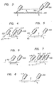
- the motions of the welding torch 200 complying with the program of Fig. l are exemplified in Figs. 4 - 8.
- the welding torch is assumed to fail in the arc start when the count N of the retry counter is 0(zero), and also when the retry counter counts N are l and 2. If the electric arc 250 has struck as shown in Fig. 4 when the retry counter count N is 5, then the corresponding position becomes the arc start point AS.
- the welding torch 200 is returned from the arc start point AS to the welding start expectation point S as shown in Fig. 5. Meantime, the return accompanies the welding of the workpiece 400 in order to keep the electric arc 250. Thereafter, as shown in Fig.
- the welding treatment is executed anew from the welding start expectation point S and along the welding expectation line l whose start point is the expectation point S.
- a section from the welding start expectation point S to the arc start point AS is welded double by the two reciprocal movements. Meanwhile, it is sometimes the case that, as shown in Fig. 7, no electric arc strikes even when the count N of the retry counter has become 9. This is a case where the retry done as the surface of the workpiece is being shaved with the welding wire is not successful.
- a method in which the welding wire retracted each time is protruded anew on each occasion is considered besides a method in which the welding wire is advanced while being pressed against the workpiece.
- the electric arc 250 is kept, but this is not for the welding as a matter of course. It is accordingly desirable to narrow down the electric arc 250 to the utmost as long as it does not disappear. This may be met, for example, in such a way that the welding condition conforming to the above intention is set at the step l3 in Fig. l and that the rated welding condition is reset at the later step 25.
Landscapes
- Engineering & Computer Science (AREA)
- Physics & Mathematics (AREA)
- Mechanical Engineering (AREA)
- Human Computer Interaction (AREA)
- Manufacturing & Machinery (AREA)
- General Physics & Mathematics (AREA)
- Automation & Control Theory (AREA)
- Plasma & Fusion (AREA)
- Optics & Photonics (AREA)
- Arc Welding Control (AREA)
- Numerical Control (AREA)
- Manipulator (AREA)
Applications Claiming Priority (2)
| Application Number | Priority Date | Filing Date | Title |
|---|---|---|---|
| JP570/86 | 1986-01-08 | ||
| JP61000570A JPH0724936B2 (ja) | 1986-01-08 | 1986-01-08 | 自動溶接装置 |
Publications (3)
| Publication Number | Publication Date |
|---|---|
| EP0229628A2 true EP0229628A2 (fr) | 1987-07-22 |
| EP0229628A3 EP0229628A3 (en) | 1989-01-25 |
| EP0229628B1 EP0229628B1 (fr) | 1991-05-08 |
Family
ID=11477367
Family Applications (1)
| Application Number | Title | Priority Date | Filing Date |
|---|---|---|---|
| EP87100097A Expired - Lifetime EP0229628B1 (fr) | 1986-01-08 | 1987-01-07 | Méthode et appareil pour le soudage automatisé |
Country Status (5)
| Country | Link |
|---|---|
| US (1) | US4772776A (fr) |
| EP (1) | EP0229628B1 (fr) |
| JP (1) | JPH0724936B2 (fr) |
| KR (1) | KR960007648B1 (fr) |
| DE (1) | DE3769802D1 (fr) |
Families Citing this family (7)
| Publication number | Priority date | Publication date | Assignee | Title |
|---|---|---|---|---|
| DE3828473A1 (de) * | 1988-08-22 | 1990-03-15 | Deggendorfer Werft Eisenbau | Mit stabelektroden arbeitender lichtbogen-schweissautomat und eine bevorzugte anwendung eines solchen |
| JP2921903B2 (ja) * | 1990-03-02 | 1999-07-19 | 株式会社日立製作所 | 溶接ロボット制御装置 |
| JPH0671437A (ja) * | 1992-08-28 | 1994-03-15 | Chiyoda Kogyo Kk | 自動溶接における再開溶接方法 |
| JP3200825B2 (ja) * | 1993-03-17 | 2001-08-20 | 株式会社安川電機 | アーク溶接ロボットの制御方法及び装置 |
| JPH0890234A (ja) * | 1994-09-21 | 1996-04-09 | Fanuc Ltd | アーク溶接ロボットにおけるアーク未発生時の制御方法 |
| AU2003296367A1 (en) * | 2002-12-05 | 2004-06-30 | Battelle Memorial Institute | Methods of removing sulfur from a fuel cell electrode |
| JP4605493B2 (ja) * | 2004-03-04 | 2011-01-05 | 株式会社安川電機 | 溶接システムの制御方法および溶接システム |
Family Cites Families (4)
| Publication number | Priority date | Publication date | Assignee | Title |
|---|---|---|---|---|
| DE1513346A1 (de) * | 1965-02-09 | 1969-09-11 | Messer Griesheim Gmbh | Steuerung von Werkzeugmaschinen durch eine Programmiervorrichtung |
| JPS5927307A (ja) * | 1982-08-04 | 1984-02-13 | Hitachi Ltd | 経路制御方法及び装置 |
| JPS5978781A (ja) * | 1982-10-27 | 1984-05-07 | Fanuc Ltd | 自動溶接機における溶接方法 |
| SE455387B (sv) * | 1983-04-08 | 1988-07-11 | Asea Ab | Sett och anordning for styrning av en svetsrobot med hjelp av ett flerfunktionsmanoverorgan (styrspak) samt anvendning av ett dylikt manoverorgan |
-
1986
- 1986-01-08 JP JP61000570A patent/JPH0724936B2/ja not_active Expired - Lifetime
-
1987
- 1987-01-07 US US07/001,165 patent/US4772776A/en not_active Expired - Lifetime
- 1987-01-07 EP EP87100097A patent/EP0229628B1/fr not_active Expired - Lifetime
- 1987-01-07 DE DE8787100097T patent/DE3769802D1/de not_active Expired - Lifetime
- 1987-01-07 KR KR1019870000042A patent/KR960007648B1/ko not_active Expired - Lifetime
Also Published As
| Publication number | Publication date |
|---|---|
| EP0229628A3 (en) | 1989-01-25 |
| KR960007648B1 (ko) | 1996-06-08 |
| KR870006951A (ko) | 1987-08-13 |
| DE3769802D1 (de) | 1991-06-13 |
| US4772776A (en) | 1988-09-20 |
| JPH0724936B2 (ja) | 1995-03-22 |
| EP0229628B1 (fr) | 1991-05-08 |
| JPS62161471A (ja) | 1987-07-17 |
Similar Documents
| Publication | Publication Date | Title |
|---|---|---|
| EP1927908A2 (fr) | Appareil de correction de position d'enseignement | |
| US4772776A (en) | Automatic welding with arc striking retry | |
| US5170034A (en) | Method and apparatus for welding robot control | |
| JP3037664B2 (ja) | 産業用ロボットの作業経路作成方法および装置 | |
| JP3117201B2 (ja) | 自動溶接方法 | |
| EP0148425A2 (fr) | Méthode et appareil pour commander inrobot | |
| JP3117199B2 (ja) | 自動溶接装置 | |
| JP3291705B2 (ja) | 切断ロボットの切断動作制御装置 | |
| JP2982955B2 (ja) | 自動溶接方法 | |
| JPH11347732A (ja) | 溶接ロボットの溶接開始点制御方法 | |
| EP4706859A2 (fr) | Appareil de soudage | |
| JPH0815659B2 (ja) | アーク溶接用ロボットにおけるアークスタートミス自動復帰方法 | |
| JPH08229683A (ja) | 自動溶接方法 | |
| JP2000141042A (ja) | 自動溶接装置 | |
| JPS5978780A (ja) | 自動溶接機における溶接再始動方法 | |
| JP2989815B2 (ja) | 自動溶接方法 | |
| JPS63144868A (ja) | ア−ク溶接方法 | |
| JP3170570B2 (ja) | 溶接ロボット | |
| JP3167696B2 (ja) | 溶接ロボットの制御方法 | |
| JPS6246884B2 (fr) | ||
| JP3140017B2 (ja) | 溶接ロボットの制御方法 | |
| JPH07195175A (ja) | 被溶接部材の端部検出方法 | |
| JPH11156544A (ja) | 自動溶接方法 | |
| JPH01278971A (ja) | 自動溶接装置の溶接スタート制御方法 | |
| JPS60154879A (ja) | ア−ク電流異常による一時停止発生後の自動処理方法 |
Legal Events
| Date | Code | Title | Description |
|---|---|---|---|
| PUAI | Public reference made under article 153(3) epc to a published international application that has entered the european phase |
Free format text: ORIGINAL CODE: 0009012 |
|
| AK | Designated contracting states |
Kind code of ref document: A2 Designated state(s): DE FR GB |
|
| PUAL | Search report despatched |
Free format text: ORIGINAL CODE: 0009013 |
|
| AK | Designated contracting states |
Kind code of ref document: A3 Designated state(s): DE FR GB |
|
| 17P | Request for examination filed |
Effective date: 19890127 |
|
| 17Q | First examination report despatched |
Effective date: 19890530 |
|
| GRAA | (expected) grant |
Free format text: ORIGINAL CODE: 0009210 |
|
| AK | Designated contracting states |
Kind code of ref document: B1 Designated state(s): DE FR GB |
|
| REF | Corresponds to: |
Ref document number: 3769802 Country of ref document: DE Date of ref document: 19910613 |
|
| ET | Fr: translation filed | ||
| PGFP | Annual fee paid to national office [announced via postgrant information from national office to epo] |
Ref country code: GB Payment date: 19911227 Year of fee payment: 6 |
|
| PLBE | No opposition filed within time limit |
Free format text: ORIGINAL CODE: 0009261 |
|
| STAA | Information on the status of an ep patent application or granted ep patent |
Free format text: STATUS: NO OPPOSITION FILED WITHIN TIME LIMIT |
|
| 26N | No opposition filed | ||
| PG25 | Lapsed in a contracting state [announced via postgrant information from national office to epo] |
Ref country code: GB Effective date: 19930107 |
|
| GBPC | Gb: european patent ceased through non-payment of renewal fee |
Effective date: 19930107 |
|
| PGFP | Annual fee paid to national office [announced via postgrant information from national office to epo] |
Ref country code: FR Payment date: 20051222 Year of fee payment: 20 |
|
| PGFP | Annual fee paid to national office [announced via postgrant information from national office to epo] |
Ref country code: DE Payment date: 20060309 Year of fee payment: 20 |