EP0229978B1 - Appareil et méthode pour changer dynamiquement la pression du liquide à écrire alimentant une tête d'imprimante à jet d'ancre - Google Patents
Appareil et méthode pour changer dynamiquement la pression du liquide à écrire alimentant une tête d'imprimante à jet d'ancre Download PDFInfo
- Publication number
- EP0229978B1 EP0229978B1 EP86117192A EP86117192A EP0229978B1 EP 0229978 B1 EP0229978 B1 EP 0229978B1 EP 86117192 A EP86117192 A EP 86117192A EP 86117192 A EP86117192 A EP 86117192A EP 0229978 B1 EP0229978 B1 EP 0229978B1
- Authority
- EP
- European Patent Office
- Prior art keywords
- pressure
- ink jet
- ink
- head
- fluid
- Prior art date
- Legal status (The legal status is an assumption and is not a legal conclusion. Google has not performed a legal analysis and makes no representation as to the accuracy of the status listed.)
- Expired
Links
- 239000012530 fluid Substances 0.000 title claims abstract description 48
- 238000000034 method Methods 0.000 title claims abstract description 8
- 230000004044 response Effects 0.000 claims description 9
- 230000003247 decreasing effect Effects 0.000 claims 1
- 230000007246 mechanism Effects 0.000 description 7
- 238000004519 manufacturing process Methods 0.000 description 5
- 230000003213 activating effect Effects 0.000 description 4
- 238000010276 construction Methods 0.000 description 4
- 238000010586 diagram Methods 0.000 description 4
- 230000008859 change Effects 0.000 description 3
- 230000001419 dependent effect Effects 0.000 description 3
- 238000007639 printing Methods 0.000 description 3
- 239000004020 conductor Substances 0.000 description 2
- 230000003287 optical effect Effects 0.000 description 2
- 230000006835 compression Effects 0.000 description 1
- 238000007906 compression Methods 0.000 description 1
- 238000009795 derivation Methods 0.000 description 1
- 239000000284 extract Substances 0.000 description 1
- 238000007641 inkjet printing Methods 0.000 description 1
- 239000003973 paint Substances 0.000 description 1
- 230000007704 transition Effects 0.000 description 1
Images

Classifications
-
- B—PERFORMING OPERATIONS; TRANSPORTING
- B41—PRINTING; LINING MACHINES; TYPEWRITERS; STAMPS
- B41J—TYPEWRITERS; SELECTIVE PRINTING MECHANISMS, i.e. MECHANISMS PRINTING OTHERWISE THAN FROM A FORME; CORRECTION OF TYPOGRAPHICAL ERRORS
- B41J2/00—Typewriters or selective printing mechanisms characterised by the printing or marking process for which they are designed
- B41J2/005—Typewriters or selective printing mechanisms characterised by the printing or marking process for which they are designed characterised by bringing liquid or particles selectively into contact with a printing material
- B41J2/01—Ink jet
- B41J2/17—Ink jet characterised by ink handling
Definitions
- This invention relates to ink jet printers and deals more particularly with an improved apparatus or circuit and related method for controlling the volume of drops ejected from an ink jet printer head by dynamically varying the pressure of writing fluid supplied to the ink jet printer head having an electri- cally energizable, activating element such as a piezoelectric one.
- a receiving surface on which a graphic is to be created is moved relative to one or more ink jet printer heads in a line scanning fashion.
- a printer head moves along a scan line, it moves past a succession of points on the line in relation to each of which the printer head may eject a drop of a writing fluid such as ink, paint, pigmented ink, etc. which lands on and prints a dot at the position.
- a writing fluid such as ink, paint, pigmented ink, etc.
- the head is actuated for each potential print point on the scan line, to eject a drop of ink for each such position, and then the drop is electrostatically controlled during its flight from the printer head to the receiving surface to either direct it onto the receiving surface or away from the receiving surface depending on whether the scan line point in question is to be printed or not.
- the actuation frequency, or the time between successive actuations is dependent on the speed of the printer head along the scan line. That is, the actuation frequency, or the time between successive actuations, will change if changes are made in the speed of the printer head relative to the receiving surface.
- printer head In another type of printer head, referred to as a "drop-on-demand" printer head, as the printer head is moved along a scan line it is actuated to produce a drop of ink only for those potential print positions along the scan line onto which the printing of dots is wanted. Therefore, the amount of time elapsing between successive actuations is dependent not only on the speed of the printer head relative to the receiving surface, but also on the pattern in accordance to which dots are to be printed along the scan line.
- Another significant factor contributing to the generation of quality graphics relates to the consistency of the size of printed dots along the scan line as the actuation frequency of the ink jet head changes. For good printing, all ejected drops should be of substantially the same volume so that all dots printed on the receiving surface by the separate drops are of substantially consistent size.
- the printer head may be actuated to print the dot at every potential print point, in which case a very short elapsed time occurs between successive actuations, and along other portions of the line, the printer head may be actuated to print the dot only at some occasional potential print points in which case the time elapsing between successive actuations is considerably lengthened.
- the fluid and mechanical dynamics tend to limit the rate at which drops having substantially the same volume and constant velocity are ejected from the printer head. Consequently, the receiving surface area coverage per unit time is substantially reduced to compensate for printer head and ink supply limitations to produce quality graphics generated by printing dots of substantially the same size.
- the maximum dynamic range over which dots are produced is further limited by the drop in the pressure of ink within the ink jet head piezo cavity.
- the volume of an ejected drop and consequently, the size of the printed dot associated with the drop is generally not equal to the volume of an ejected drop and the size of the printed dot produced at lower dot production rates.
- the limited dynamic range of dot production is most noticeable in periods of very rapid successive actuations of the ink jet head after a period of no or relatively low dot production rates.
- ink jet head piezo cavity is ink starved at the higher dot production rates because ink is ejected from the head faster than it is supplied from the ink source. This is especially troublesome during transitions from low to high dot production rates because the dots printed are not of substantially consistent size due to the varying ink volume in the ejected ink drops and the quality of the graphic produced is degraded.
- GB-A-1 408 657 discloses an ink jet recording apparatus having means operable to maintain or restore the velocity of the ink stream issuing from the nozzle to or at a predetermined velocity.
- a constant velocity ink drop is generated as a function of the temperature change of the ink utilized. The temperature affects the ink viscosity which directly affects the velocity of the ink drop ejected.
- GB-A-1 408 657 teaches a close loop system to maintain a constant ink drop velocity by maintaining a constant pressure wherein the difference between a reference pressure value and a measured pressure value of ink supplied to the nozzle is minimized.
- US-A-4 555 712 discloses an apparatus for providing feedback control of the ink drop velocity in an ink jet system.
- the ink flow between two selected points is monitored by a control device.
- the ink viscosity and/or ink pressure are changed to maintain an essentially constant velocity. Therefore, US-A-4 555 712 also teaches a closed loop system similar to GB-A-1 408 657.
- the object of the invention is to provide a circuit to supply ink to an ink jet printer head so that drops of a substantially constant volume are ejected despite changes in the time elapsing between successive actuations of the ink jet printer head.
- the present invention provides a circuit according to claim 1.
- the circuit varies the pressure of writing fluid, such as pigmented ink, supplied to an ink jet printer head in response to timing pulses from a controller or other device in which circuit the timing pulses are associated with the instantaneous actuation frequency of the printer head and correspond to the desired ink pressure at the head required to eject ink drops of consistent volume.
- Ink is supplied to the ink jet head from a fluid chamber having a pressure producing means for changing the pressure of the ink in the chamber and ink is fed to the chamber under pressure from an ink source.
- a pressure sensor is located between the fluid chamber and the ink jet head and senses the pressure of ink at the head.
- the sensor produces a signal representative of the sensed pressure at the head and the sensed pressure is compared to the desired pressure to produce a pressure modulating signal.
- the pressure modulating signal is used to excite drive means coupled to the fluid chamber pressure producing means to vary the pressure of ink in the fluid chamber.
- the fluid chamber ink pressure is related to the actuation frequency and changes in the actuation frequency produce correesponding changes in the chamber ink pressure to supply ink to the ink jet head at the desired pressure.
- the present invention therefore, provides a hydraulic circuit, particularly useful with "drop-on-demand” printer heads, but also useful with electrostatically deflected ink jet printer heads, for controlling the drop volume by dynamically varying the pressure of ink supplied to an ink jet printer head from an ink supply.
- the ink supply pressure varying circuit of the invention may be applied to a ink jet printer head forming part of any one of a wide variety of ink jet printers.
- the printer head may, for example, be the only printer head of the printer or it may be one of a plurality of printer heads included in the printer with various ones of the heads ejecting drops of different color to produce colored graphics.
- the size of the printer head and of the entire printer may very widely as may the method used for achieving relative scanning movement between the printer head or heads and the receiving surface.
- Fig. 1 shows an ink jet printer, indicated generally at 10, wherein the receiving surface 12 is located on the outside of a cylindrical drum 14 supported for rotation about a vertical axis 16.
- the drum 14 is driven in rotation, in the direction indicated by the arrow 18, about the vertical axis 16 by a drive motor 20 and the angular position of the drum with respect to the axis 16 is detected by an encoder 22.
- An ink jet printer head 24 is positioned to eject ink drops onto the receiving surface 12. As the drum 14 is rotated, the printer head 24 is moved slowly downwardly so that with each revolution of the drum, the printer head scans a new line 26 on the receiving surface 12, each scan line actually being one convolution of a continuous helical line.
- the printer head 24 is mounted on a carriage 28 and driven in the vertical direction, indicated by the arrow 30, by a lead screw 32 rotated by a drive motor 34.
- Ink is supplied to the printer head through a tube 36 connected to a pressure varying circuit embodying the present invention and described herein below.
- Electrical power for actuating the printer head is supplied to it through a set of electrical conductors 38, the conductors more particularly being connected to a piezoelectric activating element forming a part of the printer head.
- the source of drive signals for activating the printer head 24 may vary widely, but preferably and by way of example, the source may be similar to that shown in the above-reference patent application, Serial No. 634,499 filed July 26, 1984 in the name of Leonard G. Rich, entitled APPARATUS AND METHOD FOR DRIVING INK JET PRINTER, the disclosure of which application is incorporated herein by reference and to which application reference may be made for further details of the driving circuit.
- the construction of the printer head 24 may vary widely, but preferably and by way of example, the construction may be similar to that shown in the U.S. patent application, Serial No. 637,163 filed August 2, 1984 in the name of Leonard G. Rich, entitled INK-DROP EJECTING HEAD, the disclosure of which application is incorporated herein by reference and to which application reference may be made for further details of the printer head, which printer head is one having a piezoelectric activating element and is intended to eject relatively large volume ink drops adapting it to use in relatively large printers for producing large scale graphics such as billboards and display signs.
- the printer 10 is controlled by a controller 42 receiving signals from the encoder 22 and furnishing signals to the drive motors 20 and 34 creating and controlling the relative motion between the receiving surface 12 and the ink jet printer 24.
- the controller 42 is also responsive to input video signals or the like in response to which timing signals, such as indicated at 44, are output on the line 46.
- the timing signals 44 are very short duration pulses each of which dictates one actuation of the ink jet printer head 24.
- the controller 42 generates the timing pulses in synchronism with the relative movement between the receiving surface 12 and the printer head 24 so that each time the printer head is moved to a new potential print position, a timing pulse 44 is created or not depending whether or not an ink dot is to be printed at that position.
- the time elapsing between successive timing pulses 42 may vary and the minimum amount of time between any two successive timing pulses is related to the maximum relative speed between the receiving surface 12 and the printer head and the spacing between the centers of successive potential print positions along the scan line, both of which may also vary.
- the spacing between the centers of potential print positions along the scan line is such that at the maximum speed of the receiving surface relative to the printer head, the printer head has to be actuated at a frequency of 4 Kilohertz to print the dot at each potential print position, thereby making the minimum elapsed time between two successive timing pulses 44,0.25 milliseconds.
- the video signal to which the controller 42 is responsive is in the illustrated case supplied to the controller through the line 48 and may come from various different sources, the illustrated source being an optical scanner 50 connected with the controller 42 through a buffer 52.
- the scanner 50 may be an optical laser scanner which scans a continuous tone negative mounted on a drum.
- the scanner 48 is operated to rotate its drum at a faster rate than the drum 14 to scan one line on the associated negative, the information derived and relating to the one scan line being sent to the buffer 52 which temporarily stores it in a push down list storing a number of lines of information.
- the controller extracts information, that is, the video signal, for a scan line from the bottom of the pushdown list of the buffer and uses that information to generate the timing signals 44, so that through the intermediary of the buffer 52 the printer 10 and scanner 50 operate simultaneously in an online fashion.
- a pressure varying circuit is provided for maintaining the pressure of the ink supplied to the printer head 24 at a desired pressure correlating to an associated actuation frequency.
- the actuation frequency is related to the timing pulses 44 and the pressure of the ink at the printer head 24 is controlled so that ink drops of consistent volume are ejected from the printer head despite the differences in the elapsed time between successive timing pulses.
- the circuit 54 is such that in response to a dot rate command signal which signal is related to the instantaneous rate at which dots are ejected from the ink jet printer he ad 24 and representative of the desired ink pressure is produced and compared to a signal representative of the actual ink pressure at the ink jet head.
- the difference between the desired pressure and actual pressure is used to produce an error signal and the error signal is used to vary the pressure of the ink supplied to the printer head to make the actual pressure equal to the desired pressure.
- the pressure within the piezo cavity of the printer head that is varied in accordance with the actuation frequency.
- the relationship between the pressure at the input and within the piezo cavity is determined for each actuation frequency and the determined pressure at the input is the desired pressure produced by the circuit 54 to produce ink drops having a consistent volume.
- the ink supply pressure varying circuit 54 illustrated in Fig. 1 includes a frequency-to-voltage converter 56 that receives pulses 58 on the line 60 from the controller 42.
- the pulses 58 are related to the timing pulses 44 and represent the dot rate-pressure information.
- the frequency-to-voltage converter 56 in response to the pulses 58 produced by the controller 42 generates an analog signal that is representative of the desired ink pressure at the ink jet head for the instantaneous dot generation rate for the sequence of drops about to be ejected from the head.
- a buffer amplifier 64 is connected to the output 62 of the converter 56 and receives the analog output signal from the converter 56.
- the output 66 of the buffer 64 is fed to one input of a comparator 68.
- a pressure sensor 70 senses the ink pressure in the ink supply tube 36 connected to the printer head 24 and produces a signal at its output 72 representative of the ink pressure at the input to the printer head.
- the signal on the output lead 72 is fed to the input of a buffer amplifier 74 and the amplifier has its output 76 connected to another input of the comparator 68.
- the pressure sensor signal on lead 76 supplied to the comparator 68 is representative of the ink pressure at the printer head 24 for the immediately preceding sequence of drops ejected from the printer head.
- the immediate prior history of the ink pressure as represented by the signal on lead 76 is compared to the desired ink pressure as represented by the signal on lead 66 for the next sequence of drops to be ejected from the printer head.
- the signal on lead 66 corresponds to the ink pressure required at the printer head to eject a drop having a desired volume at the commanded actuation frequency.
- the output of the comparator 68 on the lead 80 is an error signal representative of the difference, if any, between the ink pressure at the printer head 24 for the immediately preceding sequence of ejected drops and the pressure associated with the sequence of drops about to be ejected.
- the error signal is fed to the input of a buffer amplifier 78 which amplifier output 82 is coupled to a hydraulic/pneumatic pressure control mechanism indicated generally within the dotted line box 84.
- the amplifier 78 produces a driving signal representative of the difference between the desired and actual ink pressures to cause the pressure control mechanism 84 to increase the pressure of the ink supplied to the printer head in accordance with the magnitude of the driving signal.
- the construction of the pressure control mechanism 84 may vary widely and may be comprised of several hydraulic and/or pneumatic elements which operate cooperatively to produce the desired ink pressure at the printer head 24 and the mechanism operates over a frequency range of zero to at least a hundred Hertz or more.
- the construction of the pressure control mechanism may be similar to that shown in the U.S. patent application filed in the names of Leonard G. Rich and Dale G. Blake, entitled HYDRAULIC SERVOMECHANISM FOR CONTROLLING THE PRESSURE OF WRITING FLUID IN AN INK JET PRINTING SYSTEM, the disclosure of which application is incorporated herein by reference and to which application reference may be made for further details of the pressure servo.
- the pressure servo disclosed in the application is one having a frequency response in the range of zero to approximately 400 Hertz.
- the pressure control mechanism 84 shown schematically in Fig. 1 comprises a variable volume fluid chamber 86 having an input 88 connected to the output of an ink supply 90.
- the ink supply 90 is pressurized from an air source 92 at a predetermined pressure supplied to an inlet 94 of the supply 90.
- the fluid chamber output 96 is coupled to the printer head inlet supply tube 36 and the pressure sensor 70.
- the fluid chamber 86 includes a diaphragm member 98 coupled to a driving mechanism 102 via a connecting member 104 and the diaphragm is arranged for reciprocating movement to vary the pressure in the chamber by varying the volume of the chamber and varying the compression of the ink within the chamber.
- the driver 102 is responsive to signals on the lead 82 and moves the member 104 and the attached diaphragm 98 to vary the pressure of the ink in the chamber 86. As more pressure is required, the driver 102 in response to the driving signal on lead 82 exerts more force on the diaphram 98 to compress the ink in the chamber 86 and accordingly increases the pressure of the ink supplied to the ink jet head.
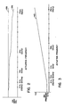
- the line 106 represents a typical response characteristic showing the performance of an ink jet printer head at different elapsed times between successive actuations, that is, at different actuation frequencies and without pressure compensation of the ink supplied to the ink jet head. From this curve 106 it is seen that the volume of an ejected drop varies considerably with elapsed time between actuations with the drop volume being substantially reduced at higher actuation frequencies.
- a desirable response characteristic is represented by the straight line 108 and is representative of the performance achieved using the hydraulic circuit of this invention. That is, in the case of the reponse characteristic 108, the volume of an ejected ink drop remains constant over the full range of elapsed times between successive pulses or actuating frequencies.
- the line 110 represents the magnitude of the ink pressure required at the input to the ink jet head to produce an ink drop having a consistent volume at each of a number of different actuation frequencies.
- the hydraulic circuit of the present invention provides a minimum pressure at the ink jet head of approximately 51,71 hPa (0.75 pounds per square inch (psi)) for the ink jet head of Figs. 1 and 2 to insure consistent volume drops at actuation frequencies ranging from 0 to approximately 250 dots/second to a maximum pressure of 344,74 hPa (5 psi) for a dot generation rate of 4000 dots/second.
- a minimum pressure of 51,71 hPa (0.75 psi) is maintained at the printer head during periods of zero dot generation to anticipate any delay in drop ejection due to fluid dynamics, etc. Consequently, the dynamic range over which an ink jet printer head ejects ink drops having substantially the same volume, is expanded through use of the hydraulic circuit of the present invention.
- the printer head operates satisfactority at higher actuation frequencies up to 4 Kilohertz and produces a greater surface area coverage per unit time than an equivalent ink jet printer head supplied with ink from a source without the hydraulic circuit.
- the dot rate command signal which is related to the instantaneous rate at which dots are ejected from the printer head 24 in Fig. 1 and representative of the desired ink pressure at the input to the ink jet head is generated by the controller 42 as a digital word rather than a series of pulses 58 related to the timing pulses 44.
- a number of digital words are stored in the controller 42 and each digital word contains information related to the desired ink pressure at the ink jet head for an associated actuation frequency to produce the desired volume ink drop for the particular type ink jet printer head used.
- the frequency-to-voltage converter 56 is replaced by a digital-to-analog converter which receives the digital words from the controller 42 and generates the appropriate analog signal on lead 62 representative of the desired pressure at the ink jet head.
- a digital-to-analog converter which receives the digital words from the controller 42 and generates the appropriate analog signal on lead 62 representative of the desired pressure at the ink jet head.
Landscapes
- Particle Formation And Scattering Control In Inkjet Printers (AREA)
- Ink Jet (AREA)
Claims (6)
- Circuit pour commander le volume de gouttes éjectées d'une tête (24) d'impression à jet d'encre par modification dynamique de la pression du fluide d'écriture fourni à la tête (24) d'impression par jet d'encre en réponse à des impulsions (58) de commande qui peuvent apparaitre à des intervalles variables de temps entre des impulsions successives de ces impulsions, ce circuit comprenant :
une source sous pression (90,92) de fluide d'écriture ;
une tête (24) d'impression par jet d'encre ;
une chambre de fluide (86) ayant un moyen d'arrivée (88) raccordé à ladite source (90,92) de fluide d'écriture et un moyen de sortie (96) raccordé à ladite tête (24) d'impression par jet d'encre, cette chambre de fluide (86) ayant en plus un moyen (98) de production d'une pression pour modifier la pression du fluide d'écriture dans la chambre de fluide (86) ;
une source (42) d'impulsions (58) de commande, ces impulsions de commande étant associées à la fréquence (44) instantanée de manoeuvre de la tête (24) d'impression et correspondantes à la grandeur d'une pression prédéterminée du fluide à la tête (24) d'impression par jet d'encre afin de produire une goutte d'encre ayant un volume prédéterminé ;
un moyen (70) pour détecter la pression du fluide d'écriture à la tête (24) d'impression par jet d'encre et pour créer un premier signal de pression ;
des moyens (56,64) sensibles aux impulsions de commande pour créer un second signal de pression en accord avec le nombre et la fréquence desdites impulsions de commande, ce second signal de pression étant prédéterminé et représentatif de la pression de fluide prédéterminée requise à la tête à jet d'encre correspondante à la fréquence instantanée de manoeuvre ;
un moyen (68) comparateur pour comparer le premier signal et le second signal de pression afin de produire un signal de commande de pression préalablement à l'éjection des gouttes d'encre à la fréquence instantanée de manoeuvre hors de la tête (24) à jet d'encre, ce signal de commande de pression étant représentatif de la différence de pression entre la pression détectée du fluide et la pression prédéterminée désirée du fluide à la tête (24) à jet d'encre, et
un moyen (102) d'entraînement couplé au moyen (98) de production de la pression dans la chambre de fluide et sensible au signal de commande de pression pour entraîner le moyen (98) de mise sous pression afin de modifier dynamiquement la pression du fluide d'écriture dans la chambre de fluide (86) pour fournir le fluide d'écriture à la tête (24) d'impression par jet d'encre à la pression prédéterminée désirée associée à la fréquence de manoeuvre de la tête à jet d'encre, de sorte que des gouttes d'encre ayant un volume consistant sont éjectées de la tête (24) à jet d'encre pour chacune de plusieurs fréquences de fréquence instantanée différentes de manoeuvre. - Circuit tel que défini à la revendication 1 caractérisé en outre par le moyen générateur du second signal de pression comprenant
un moyen (56) convertisseur de fréquence en tension couplé avec le moyen (42) servant de source des impulsions de commande pour produire un premier signal électrique analogique, ce premier signal analogique ayant une grandeur proportionnelle à la pression prédéterminée désirée du fluide d'écriture à la tête (24) à jet d'encre et correspondant au débit instantané auquel une séquence de gouttes est éjectée de la tête (24) à jet d'encre. - Circuit tel que défini dans la renvendication 1 ou 2 caractérisé en outre par le moyen générateur du premier signal de pression incluant ledit moyen (70) de détection de pression produisant un second signal électrique analogique, ce second signal analogique ayant une grandeur proportionnelle à la pression du fluide d'écriture présent à la tête (24) à jet d'encre pendant l'éjection d'une séquence de gouttes à partir de cette tête (24) à jet d'encre.
- Circuit tel que défini dans l'une des revendications 1 à 3 caractérisé en outre par le moyen de production de la pression dans la chambre de fluide comprenant une membrane (98) constituant un côté de ladite chambre (86) et étant mobile pour l'augmentation et la diminution du volume de cette chambre (86) afin de faire varier la pression du fluide dans cette même chambre (86).
- Circuit tel que défini dans les revendications 1 à 4 caractérisé en outre par :
une tête d'impression à jet d'encre fournissant à la demande des gouttes à grand volume ;
le moyen de détection de la pression comprenant un détecteur de pression (79) situé entre la sortie de la chambre de fluide et ladite tête à jet d'encre pour détecter la pression du fluide d'écriture à la tête et pour créer le premier signal de pression ;
un moyen tampon amplificateur (74) couplé au détecteur (70) de pression pour la réception du premier signal de pression et la production du second signal électrique analogique ;
le moyen comparateur comparant le premier signal et le second signal électriques analogiques pour produire le signal de commande de pression. - Procédé pour contrôler le volume de gouttes éjectées d'une tête (24) d'impression à jet d'encre par la variation dynamique de la pression du fluide d'écriture fourni à la tête (24) d'impression à jet d'encre et pour faire que cette tête éjecte des gouttes ayant un volume consistant dans une gamme de fréquences de manoeuvre de la tête à jet d'encre, ce procédé comprenant des opérations de :
produire une série d'impulsions (58) de commande qui peuvent apparaître à des intervalles variables de temps entre des impulsions successives de ces impulsions, ces impulsions de commande étant associées à la fréquence instantanée d'actionnement de la tête (24) à jet d'encre ;
créer un signal de pression de fluide correspondant à un débit actuel d'éjection des gouttes à partir de la tête (24) à jet d'encre ;
créer un signal de pression prédéterminé du fluide à la tête à jet d'encre associé à la pression requise à la tête (24) pour éjecter une goutte ayant un volume désiré et en accord avec les impulsions de commande et correspondant à un débit prochain d'éjection des gouttes hors de la tête (24) à jet d'encre ;
comparer les signaux de pression du débit présent et du débit prochain d'éjection des gouttes pour produire un signal de commande de pression avant l'éjection des gouttes d'encre à la fréquence instantanée d'actionnement de la tête (24) à jet d'encre ; et
modifier dynamiquement la pression du fluide d'écriture dans ladite source (86) de fluide d'écriture en relation avec ledit signal de commande de pression, de façon que la pression du fluide d'écriture fournie à la tête (24) à jet d'encre se trouve à la pression prédéterminée du fluide associée à la fréquence instantanée d'actionnement pour faire que la tête éjecte des gouttes à volume consistant à chaque débit d'éjection de gouttes.
Priority Applications (1)
| Application Number | Priority Date | Filing Date | Title |
|---|---|---|---|
| AT86117192T ATE65964T1 (de) | 1986-01-17 | 1986-12-10 | Geraet und verfahren zur dynamischen aenderung des schreibfluessigkeitsdruckes zur speisung eines tintenstrahldruckkopfes. |
Applications Claiming Priority (2)
| Application Number | Priority Date | Filing Date | Title |
|---|---|---|---|
| US06/820,520 US4651161A (en) | 1986-01-17 | 1986-01-17 | Dynamically varying the pressure of fluid to an ink jet printer head |
| US820520 | 1986-01-17 |
Publications (3)
| Publication Number | Publication Date |
|---|---|
| EP0229978A2 EP0229978A2 (fr) | 1987-07-29 |
| EP0229978A3 EP0229978A3 (en) | 1988-04-06 |
| EP0229978B1 true EP0229978B1 (fr) | 1991-08-07 |
Family
ID=25231028
Family Applications (1)
| Application Number | Title | Priority Date | Filing Date |
|---|---|---|---|
| EP86117192A Expired EP0229978B1 (fr) | 1986-01-17 | 1986-12-10 | Appareil et méthode pour changer dynamiquement la pression du liquide à écrire alimentant une tête d'imprimante à jet d'ancre |
Country Status (9)
| Country | Link |
|---|---|
| US (1) | US4651161A (fr) |
| EP (1) | EP0229978B1 (fr) |
| JP (1) | JPH078567B2 (fr) |
| AT (1) | ATE65964T1 (fr) |
| CA (1) | CA1266201A (fr) |
| DE (1) | DE3680779D1 (fr) |
| ES (1) | ES2023806B3 (fr) |
| GR (1) | GR3003082T3 (fr) |
| HK (1) | HK66593A (fr) |
Families Citing this family (17)
| Publication number | Priority date | Publication date | Assignee | Title |
|---|---|---|---|---|
| US4700205A (en) * | 1986-01-17 | 1987-10-13 | Metromedia Company | Hydraulic servomechanism for controlling the pressure of writing fluid in an ink jet printing system |
| GB8708884D0 (en) * | 1987-04-14 | 1987-05-20 | Domino Printing Sciences Plc | Control of ink jet printing system |
| JP2675851B2 (ja) * | 1989-01-28 | 1997-11-12 | キヤノン株式会社 | インクジェット記録方法及び該方法に用いる装置 |
| US5394177A (en) * | 1992-05-29 | 1995-02-28 | Scitex Digital Printing, Inc. | Four inch fluid system |
| US5489925A (en) * | 1993-05-04 | 1996-02-06 | Markem Corporation | Ink jet printing system |
| US6203759B1 (en) | 1996-05-31 | 2001-03-20 | Packard Instrument Company | Microvolume liquid handling system |
| US6537817B1 (en) | 1993-05-31 | 2003-03-25 | Packard Instrument Company | Piezoelectric-drop-on-demand technology |
| US6521187B1 (en) | 1996-05-31 | 2003-02-18 | Packard Instrument Company | Dispensing liquid drops onto porous brittle substrates |
| US6083762A (en) * | 1996-05-31 | 2000-07-04 | Packard Instruments Company | Microvolume liquid handling system |
| US7004557B2 (en) * | 2002-07-29 | 2006-02-28 | Fuji Photo Film Co., Ltd. | Liquid ejecting device |
| US6923866B2 (en) * | 2003-06-13 | 2005-08-02 | Spectra, Inc. | Apparatus for depositing droplets |
| US7467858B2 (en) * | 2005-10-12 | 2008-12-23 | Hewlett-Packard Development Company, L.P. | Back pressure control in inkjet printing |
| JP2008104965A (ja) * | 2006-10-26 | 2008-05-08 | Seiko Epson Corp | 液滴吐出ヘッドの制御方法、描画方法及び液滴吐出装置 |
| US8608267B2 (en) * | 2008-06-30 | 2013-12-17 | Fujifilm Dimatix, Inc. | Ink jetting |
| JP6225660B2 (ja) * | 2013-11-20 | 2017-11-08 | セイコーエプソン株式会社 | 記録装置 |
| RU2608081C2 (ru) * | 2015-06-26 | 2017-01-13 | Федеральное государственное бюджетное образовательное учреждение высшего профессионального образования "Ивановский государственный энергетический университет имени В.И. Ленина" (ИГЭУ) | Способ компенсации влияния гармонических колебаний момента нагрузки в электромеханической системе и устройство для его осуществления |
| JP6668386B2 (ja) * | 2016-02-05 | 2020-03-18 | 株式会社ワコム | 電子ペン |
Family Cites Families (10)
| Publication number | Priority date | Publication date | Assignee | Title |
|---|---|---|---|---|
| JPS4871538A (fr) * | 1971-12-27 | 1973-09-27 | ||
| US3787882A (en) * | 1972-09-25 | 1974-01-22 | Ibm | Servo control of ink jet pump |
| US3771568A (en) * | 1972-12-06 | 1973-11-13 | Dick Co Ab | Ink analyzer and compensator |
| US4215353A (en) * | 1976-04-01 | 1980-07-29 | Minolta Camera Kabushiki Kaisha | Ink jet recording apparatus with trial run at side |
| US4045770A (en) * | 1976-11-11 | 1977-08-30 | International Business Machines Corporation | Method and apparatus for adjusting the velocity of ink drops in an ink jet printer |
| US4314263A (en) * | 1980-07-17 | 1982-02-02 | Carley Adam L | Fluid jet apparatus |
| JPS5838317A (ja) * | 1981-08-28 | 1983-03-05 | Tokyo Radiator Seizo Kk | 内燃機関の冷却装置 |
| JPS5941273A (ja) * | 1982-09-01 | 1984-03-07 | Ricoh Co Ltd | 偏向制御インクジエツト記録装置 |
| US4562445A (en) * | 1984-07-26 | 1985-12-31 | Metromedia, Inc. | Apparatus and method for driving ink jet printer |
| US4555712A (en) * | 1984-08-03 | 1985-11-26 | Videojet Systems International, Inc. | Ink drop velocity control system |
-
1986
- 1986-01-17 US US06/820,520 patent/US4651161A/en not_active Expired - Lifetime
- 1986-12-10 AT AT86117192T patent/ATE65964T1/de not_active IP Right Cessation
- 1986-12-10 ES ES86117192T patent/ES2023806B3/es not_active Expired - Lifetime
- 1986-12-10 EP EP86117192A patent/EP0229978B1/fr not_active Expired
- 1986-12-10 DE DE8686117192T patent/DE3680779D1/de not_active Expired - Lifetime
-
1987
- 1987-01-16 JP JP62007986A patent/JPH078567B2/ja not_active Expired - Fee Related
- 1987-01-16 CA CA000527537A patent/CA1266201A/fr not_active Expired
-
1991
- 1991-11-07 GR GR91401694T patent/GR3003082T3/el unknown
-
1993
- 1993-07-08 HK HK665/93A patent/HK66593A/en not_active IP Right Cessation
Also Published As
| Publication number | Publication date |
|---|---|
| HK66593A (en) | 1993-07-16 |
| JPH078567B2 (ja) | 1995-02-01 |
| ATE65964T1 (de) | 1991-08-15 |
| EP0229978A3 (en) | 1988-04-06 |
| JPS62170357A (ja) | 1987-07-27 |
| GR3003082T3 (en) | 1993-02-17 |
| CA1266201A (fr) | 1990-02-27 |
| ES2023806B3 (es) | 1992-02-16 |
| DE3680779D1 (de) | 1991-09-12 |
| EP0229978A2 (fr) | 1987-07-29 |
| US4651161A (en) | 1987-03-17 |
Similar Documents
| Publication | Publication Date | Title |
|---|---|---|
| US4651161A (en) | Dynamically varying the pressure of fluid to an ink jet printer head | |
| EP0229320B1 (fr) | Servomécanisme hydraulique pour commander la pression de liquide à écrire dans un système d'imprimante à jet d'ancre | |
| EP0147575B1 (fr) | Imprimante à projection d'encre à éjection à la demande des gouttes | |
| CA2152967C (fr) | Systeme d'impression haute frequence a jet d'encre goutte a la demande | |
| JPS6127192B2 (fr) | ||
| US5221931A (en) | Driving method for ink jet recording head and ink jet recording apparatus performing the method | |
| JPH0632922B2 (ja) | インクジェット印字ヘッドの駆動回路と駆動方法 | |
| US6386664B1 (en) | Ink-jet recording apparatus | |
| WO1992000849A1 (fr) | Tete d'impression | |
| US6726299B2 (en) | Ink jet recording apparatus, method of controlling the apparatus, and recording medium having the method recorded thereon | |
| US4337470A (en) | Ink jet printing apparatus with variable character size | |
| EP0799708B1 (fr) | Méthode d'impression à haute vitesse et appareil d'enregistrement à jet d'encre l'utilisant | |
| US6059394A (en) | Driving method for ink jet recording head | |
| JPH10217444A (ja) | インクジェット式記録装置 | |
| JPH10296971A (ja) | インクジェット記録装置 | |
| US6328402B1 (en) | Ink jet recording apparatus that can reproduce half tone image without degrading picture quality | |
| JPH09169111A (ja) | インクジェットプリンタ | |
| EP0390125B1 (fr) | Méthode et appareil à enregistrer | |
| US6457798B1 (en) | Six gray level roofshooter fluid ejector | |
| KR950011533B1 (ko) | 양쪽방향 기록용 직렬기록장치 | |
| JPH05261906A (ja) | 回転式インクジェットヘッド | |
| EP4414175A1 (fr) | Tête d'éjection de liquide, dispositif d'éjection de liquide et imprimante à jet d'encre | |
| JP3135101B2 (ja) | 連続噴射型インクジェット記録装置 | |
| JPH10250068A (ja) | インクジェット記録装置 | |
| JP2007313896A (ja) | 画像形成方法及びその方法を実行するインクジェットプリンタ |
Legal Events
| Date | Code | Title | Description |
|---|---|---|---|
| PUAI | Public reference made under article 153(3) epc to a published international application that has entered the european phase |
Free format text: ORIGINAL CODE: 0009012 |
|
| AK | Designated contracting states |
Kind code of ref document: A2 Designated state(s): AT BE CH DE ES FR GB GR IT LI LU NL SE |
|
| RAP1 | Party data changed (applicant data changed or rights of an application transferred) |
Owner name: METROMEDIA COMPANY |
|
| PUAL | Search report despatched |
Free format text: ORIGINAL CODE: 0009013 |
|
| AK | Designated contracting states |
Kind code of ref document: A3 Designated state(s): AT BE CH DE ES FR GB GR IT LI LU NL SE |
|
| 17P | Request for examination filed |
Effective date: 19880603 |
|
| 17Q | First examination report despatched |
Effective date: 19900115 |
|
| GRAA | (expected) grant |
Free format text: ORIGINAL CODE: 0009210 |
|
| AK | Designated contracting states |
Kind code of ref document: B1 Designated state(s): AT BE CH DE ES FR GB GR IT LI LU NL SE |
|
| REF | Corresponds to: |
Ref document number: 65964 Country of ref document: AT Date of ref document: 19910815 Kind code of ref document: T |
|
| REF | Corresponds to: |
Ref document number: 3680779 Country of ref document: DE Date of ref document: 19910912 |
|
| ITF | It: translation for a ep patent filed | ||
| ET | Fr: translation filed | ||
| REG | Reference to a national code |
Ref country code: ES Ref legal event code: FG2A Ref document number: 2023806 Country of ref document: ES Kind code of ref document: B3 |
|
| PLBE | No opposition filed within time limit |
Free format text: ORIGINAL CODE: 0009261 |
|
| STAA | Information on the status of an ep patent application or granted ep patent |
Free format text: STATUS: NO OPPOSITION FILED WITHIN TIME LIMIT |
|
| 26N | No opposition filed | ||
| REG | Reference to a national code |
Ref country code: GR Ref legal event code: FG4A Free format text: 3003082 |
|
| REG | Reference to a national code |
Ref country code: CH Ref legal event code: PFA Free format text: METROMEDIA COMPANY |
|
| ITPR | It: changes in ownership of a european patent |
Owner name: CAMBIO SEDE;METROMEDIA COMPANY |
|
| EPTA | Lu: last paid annual fee | ||
| EAL | Se: european patent in force in sweden |
Ref document number: 86117192.4 |
|
| PGFP | Annual fee paid to national office [announced via postgrant information from national office to epo] |
Ref country code: LU Payment date: 19961101 Year of fee payment: 11 |
|
| PGFP | Annual fee paid to national office [announced via postgrant information from national office to epo] |
Ref country code: GB Payment date: 19961113 Year of fee payment: 11 |
|
| PGFP | Annual fee paid to national office [announced via postgrant information from national office to epo] |
Ref country code: BE Payment date: 19961114 Year of fee payment: 11 |
|
| PGFP | Annual fee paid to national office [announced via postgrant information from national office to epo] |
Ref country code: FR Payment date: 19961118 Year of fee payment: 11 |
|
| PGFP | Annual fee paid to national office [announced via postgrant information from national office to epo] |
Ref country code: DE Payment date: 19961120 Year of fee payment: 11 Ref country code: CH Payment date: 19961120 Year of fee payment: 11 |
|
| PGFP | Annual fee paid to national office [announced via postgrant information from national office to epo] |
Ref country code: SE Payment date: 19961121 Year of fee payment: 11 |
|
| PGFP | Annual fee paid to national office [announced via postgrant information from national office to epo] |
Ref country code: AT Payment date: 19961122 Year of fee payment: 11 |
|
| PGFP | Annual fee paid to national office [announced via postgrant information from national office to epo] |
Ref country code: NL Payment date: 19961128 Year of fee payment: 11 |
|
| PGFP | Annual fee paid to national office [announced via postgrant information from national office to epo] |
Ref country code: GR Payment date: 19961216 Year of fee payment: 11 |
|
| PGFP | Annual fee paid to national office [announced via postgrant information from national office to epo] |
Ref country code: ES Payment date: 19961230 Year of fee payment: 11 |
|
| PG25 | Lapsed in a contracting state [announced via postgrant information from national office to epo] |
Ref country code: LU Free format text: LAPSE BECAUSE OF NON-PAYMENT OF DUE FEES Effective date: 19971210 Ref country code: GB Free format text: LAPSE BECAUSE OF NON-PAYMENT OF DUE FEES Effective date: 19971210 Ref country code: AT Free format text: LAPSE BECAUSE OF NON-PAYMENT OF DUE FEES Effective date: 19971210 |
|
| PG25 | Lapsed in a contracting state [announced via postgrant information from national office to epo] |
Ref country code: SE Free format text: LAPSE BECAUSE OF NON-PAYMENT OF DUE FEES Effective date: 19971211 Ref country code: ES Free format text: LAPSE BECAUSE OF THE APPLICANT RENOUNCES Effective date: 19971211 |
|
| PG25 | Lapsed in a contracting state [announced via postgrant information from national office to epo] |
Ref country code: LI Free format text: LAPSE BECAUSE OF NON-PAYMENT OF DUE FEES Effective date: 19971231 Ref country code: GR Free format text: LAPSE BECAUSE OF NON-PAYMENT OF DUE FEES Effective date: 19971231 Ref country code: FR Free format text: THE PATENT HAS BEEN ANNULLED BY A DECISION OF A NATIONAL AUTHORITY Effective date: 19971231 Ref country code: CH Free format text: LAPSE BECAUSE OF NON-PAYMENT OF DUE FEES Effective date: 19971231 Ref country code: BE Free format text: LAPSE BECAUSE OF NON-PAYMENT OF DUE FEES Effective date: 19971231 |
|
| BERE | Be: lapsed |
Owner name: METROMEDIA CY Effective date: 19971231 |
|
| PG25 | Lapsed in a contracting state [announced via postgrant information from national office to epo] |
Ref country code: NL Free format text: LAPSE BECAUSE OF NON-PAYMENT OF DUE FEES Effective date: 19980701 |
|
| GBPC | Gb: european patent ceased through non-payment of renewal fee |
Effective date: 19971210 |
|
| REG | Reference to a national code |
Ref country code: CH Ref legal event code: PL |
|
| NLV4 | Nl: lapsed or anulled due to non-payment of the annual fee |
Effective date: 19980701 |
|
| PG25 | Lapsed in a contracting state [announced via postgrant information from national office to epo] |
Ref country code: DE Free format text: LAPSE BECAUSE OF NON-PAYMENT OF DUE FEES Effective date: 19980901 |
|
| EUG | Se: european patent has lapsed |
Ref document number: 86117192.4 |
|
| REG | Reference to a national code |
Ref country code: FR Ref legal event code: ST |
|
| REG | Reference to a national code |
Ref country code: ES Ref legal event code: FD2A Effective date: 20010402 |
|
| PG25 | Lapsed in a contracting state [announced via postgrant information from national office to epo] |
Ref country code: IT Free format text: LAPSE BECAUSE OF NON-PAYMENT OF DUE FEES Effective date: 20051210 |