EP0230237A2 - Armoire, en particulier pour salle de bains - Google Patents
Armoire, en particulier pour salle de bains Download PDFInfo
- Publication number
- EP0230237A2 EP0230237A2 EP87100218A EP87100218A EP0230237A2 EP 0230237 A2 EP0230237 A2 EP 0230237A2 EP 87100218 A EP87100218 A EP 87100218A EP 87100218 A EP87100218 A EP 87100218A EP 0230237 A2 EP0230237 A2 EP 0230237A2
- Authority
- EP
- European Patent Office
- Prior art keywords
- housing
- doors
- cabinet
- shells
- cabinet according
- Prior art date
- Legal status (The legal status is an assumption and is not a legal conclusion. Google has not performed a legal analysis and makes no representation as to the accuracy of the status listed.)
- Granted
Links
Images


Classifications
-
- E—FIXED CONSTRUCTIONS
- E06—DOORS, WINDOWS, SHUTTERS, OR ROLLER BLINDS IN GENERAL; LADDERS
- E06B—FIXED OR MOVABLE CLOSURES FOR OPENINGS IN BUILDINGS, VEHICLES, FENCES OR LIKE ENCLOSURES IN GENERAL, e.g. DOORS, WINDOWS, BLINDS, GATES
- E06B3/00—Window sashes, door leaves, or like elements for closing wall or like openings; Layout of fixed or moving closures, e.g. windows in wall or like openings; Features of rigidly-mounted outer frames relating to the mounting of wing frames
- E06B3/90—Revolving doors; Cages or housings therefor
- E06B3/903—Revolving doors; Cages or housings therefor consisting of arcuate wings revolving around a parallel axis situated outside the wing, e.g. a cylindrical wing revolving around its axis
-
- A—HUMAN NECESSITIES
- A47—FURNITURE; DOMESTIC ARTICLES OR APPLIANCES; COFFEE MILLS; SPICE MILLS; SUCTION CLEANERS IN GENERAL
- A47B—TABLES; DESKS; OFFICE FURNITURE; CABINETS; DRAWERS; GENERAL DETAILS OF FURNITURE
- A47B67/00—Chests; Dressing-tables; Medicine cabinets or the like; Cabinets characterised by the arrangement of drawers
-
- A—HUMAN NECESSITIES
- A47—FURNITURE; DOMESTIC ARTICLES OR APPLIANCES; COFFEE MILLS; SPICE MILLS; SUCTION CLEANERS IN GENERAL
- A47K—SANITARY EQUIPMENT; ACCESSORIES THEREFOR, e.g. TOILET ACCESSORIES
- A47K3/00—Baths; Showers; Appurtenances therefor
- A47K3/28—Showers or bathing douches
- A47K3/281—Accessories for showers or bathing douches, e.g. cleaning devices for walls or floors of showers
-
- E—FIXED CONSTRUCTIONS
- E06—DOORS, WINDOWS, SHUTTERS, OR ROLLER BLINDS IN GENERAL; LADDERS
- E06B—FIXED OR MOVABLE CLOSURES FOR OPENINGS IN BUILDINGS, VEHICLES, FENCES OR LIKE ENCLOSURES IN GENERAL, e.g. DOORS, WINDOWS, BLINDS, GATES
- E06B3/00—Window sashes, door leaves, or like elements for closing wall or like openings; Layout of fixed or moving closures, e.g. windows in wall or like openings; Features of rigidly-mounted outer frames relating to the mounting of wing frames
- E06B3/32—Arrangements of wings characterised by the manner of movement; Arrangements of movable wings in openings; Features of wings or frames relating solely to the manner of movement of the wing
- E06B3/34—Arrangements of wings characterised by the manner of movement; Arrangements of movable wings in openings; Features of wings or frames relating solely to the manner of movement of the wing with only one kind of movement
- E06B3/42—Sliding wings; Details of frames with respect to guiding
- E06B3/46—Horizontally-sliding wings
- E06B3/4663—Horizontally-sliding wings specially adapted for furniture
-
- E—FIXED CONSTRUCTIONS
- E05—LOCKS; KEYS; WINDOW OR DOOR FITTINGS; SAFES
- E05Y—INDEXING SCHEME ASSOCIATED WITH SUBCLASSES E05D AND E05F, RELATING TO CONSTRUCTION ELEMENTS, ELECTRIC CONTROL, POWER SUPPLY, POWER SIGNAL OR TRANSMISSION, USER INTERFACES, MOUNTING OR COUPLING, DETAILS, ACCESSORIES, AUXILIARY OPERATIONS NOT OTHERWISE PROVIDED FOR, APPLICATION THEREOF
- E05Y2900/00—Application of doors, windows, wings or fittings thereof
- E05Y2900/10—Application of doors, windows, wings or fittings thereof for buildings or parts thereof
- E05Y2900/13—Type of wing
- E05Y2900/132—Doors
Definitions
- the invention relates to a cabinet, in particular for bathrooms and for receiving bathing utensils or the like, with a housing which has a curved wall and a floor and a lid, and with a door arranged around an axis of rotation for closing or uncovering an opening which is present between two longitudinal edges of the housing.
- Cupboards of this type are known in a wide variety of configurations and are used, for example, in a bathroom for storing and holding bath or washing utensils, cosmetics and other things for daily personal care.
- Small cabinets, shelves or the like are also known, which are to be arranged in a niche or in a corner of the room.
- the previously known cabinets have relatively large external dimensions, and it is also difficult to access the interior of the housing. Difficulties arise with regard to a functional division and utilization of the interior, especially since the parts located in the rear area are difficult to access if the depth is too great.
- the housing wall is cylindrical.
- the housing base and the housing cover contain ring grooves, in which the housing wall is inserted with its lower or upper end.
- the housing base and the housing cover are connected to one another by means of a central axis which is passed through a central hole in the base, penetrates the entire interior of the housing and is connected to the housing cover in a separate fastening device at the top.
- a carousel which is rotatably mounted about the axis mentioned and serves to hold bottles.
- a curved door is provided, which is arranged in opposing ring grooves from the housing base and housing cover.
- the radii of curvature of the door and the guide grooves must be exactly matched to each other and tight manufacturing tolerances must be observed.
- the housing and the door must be solid, so that the pivoting door can also be moved at any time; a corresponding expenditure of material and a corresponding weight are the result.
- foreign objects that get stuck in the guide grooves can at least make it difficult, if not completely, impossible for the door to pivot freely.
- the invention is therefore based on the object of providing a cupboard which, with a simple and inexpensive construction, has good accessibility to the interior and a compact structure.
- the cabinet should have a pleasing design and have good stability with low weight.
- the manufacture and assembly of the cabinet should be carried out with little effort, and a reliable operation of the door or doors should be guaranteed.
- the cabinet should be able to be arranged in the corner area or in a niche of a room without any problems, whereby the volume of the hanging or installation area is largely used by the cabinet, and thus ultimately an optimal use of the available space.
- a second door is rotatably arranged about a second axis of rotation, which is at a distance from the first axis of rotation, that the two pivotable doors each have a bearing element at the lower and upper ends, and that the bearing elements and the doors are provided by means of pins are rotatably mounted in the housing base and housing cover.
- the cabinet according to the invention has compact external dimensions and enables optimal use of the interior. Due to the two doors that can be pivoted relative to one another, the axes of rotation of which are spaced apart, a large housing opening can be closed or released in a functionally reliable manner with a small space and weight requirement.
- the bearing shells ensure reliable operation of the doors with little design effort, without a malfunction of the function being expected due to dirt, foreign bodies or the like.
- the housing walls and doors which are axially parallel and in particular coaxial, as well as the entire cabinet, can be manufactured inexpensively and expediently consist of curved metal profiles.
- the housing walls and doors mentioned are approximately quarter-circular shells, although shapes that deviate from the circle may also be within the scope of this invention.
- the door shells and the housing shells are parallel to the axis in such a way that in the open state the opening which extends practically over the entire width of the cabinet is essentially completely cleared.
- the distance between the front edges of the housing shells is only insignificantly smaller than the overall width of the cabinet, so that the interior and the intermediate floors, hooks or the like arranged in it are very easily accessible.
- intermediate shelves which according to the invention are adjustable in the direction of the longitudinal axes, are also provided with a correspondingly curved, adapted contour.
- housing shells and also the door shells can also be essentially straight and have parts designed as webs or the like, the pivotability of the door shells according to the invention being ensured, however, by appropriate arrangement of the longitudinal axes.
- the mutually pivotable door shells completely close the opening or the entire cupboard in the closed state, so that the penetration of splash water can be largely ruled out when installed in the bathroom or in a shower cubicle.
- the housing on the rear side of the housing shells has webs which essentially extend over the entire length and which are preferably connected to one another by means of a clamping profile.
- the housing shells and in particular the webs mentioned have screw channels which enable the fastening of a housing cover and a housing base at the upper or lower end by means of screws or the like.
- the manufacture and assembly can be carried out inexpensively, especially since the housing base and housing cover are expediently designed to match.
- the housing shells expediently consist of metal profiles and are inserted between the housing base and the housing cover.
- the one-piece construction of the two housing shells including webs or the like is also within the scope of the invention, preferably from a plastic, in order to be produced in suitable injection molds.
- the housing shells and also the two door shells extend over angular ranges greater than 90 °, with angular ranges on the order of 110 ° having proven particularly expedient.
- the housing shells form the side walls and at the same time form part of the rear wall, which is completed by the fastening bracket arranged between the housing shells.
- the width of the fastening bracket is approximately the same as the distance between the longitudinal axes of the two housing shells. The distance mentioned is on the order of 20% larger than the radius of the housing shells. Because of this configuration, there is an indentation in the area of the opening, into which the two door shells pivot with their front edges. Nevertheless, the cupboard has an approximately oval layout, and a comparatively small depth is achieved. This indentation on the front of the cabinet results in a particularly good design, but within the scope of this invention this area can also be designed to increase the usable internal volume.
- the bearing elements are configured in a sector-like manner and engage with the housing cover or the housing base via a pin or the like. These bearing elements are designed as a cover cap to close the door shells at the ends, specifically across the longitudinal axes. According to the invention, the bearing elements also serve to stabilize and to support the door shells, which can thus be formed with a comparatively small wall thickness, nevertheless ensuring high torsional rigidity and ultimately smooth movement and pivoting of the doors or door shells over a long service life.
- the respective door shell is inserted into recesses, grooves or the like in the associated cover cap, which is made of an injection molded plastic.
- the bearing elements or cover caps have an edge adapted to the curved contour of the door shells, which forms a support and support and ensures good stability and ultimately ease of movement.
- toothed segments or toothings which are in engagement with one another are assigned to the door shells and in particular the bearing elements. Due to these tooth segments, the actuation and handling is not insignificantly improved. It is sufficient to operate one door shell with one hand to open or close the opening of the cabinet.
- the 1 shows two curved housing walls 2, 4, which have webs 7, 8 in the area of the rear side 6 of the cabinet, which in turn are connected to one another by means of a clamping profile 9 which extends over the entire length are.
- the connection of the housing walls 2, 4 with an upper housing cover and a lower housing base 5, which are designed to match and between which the two housing walls 2, 4 are arranged in the direction of the axes 10, 11, is carried out by means of screws or the like, which are inserted into screw channels 13, 14 engage on the outside of the webs 7, 8 from above or from below.
- the two housing walls 2, 4 are arcuate or formed as parts of cylinders and extend around the axes 10 and 11 over an angular range of approximately 110 °.
- the axes 10 and 11 are at a distance 12 in a plane parallel to the opening 18, which is essentially the same size as the outer radius 17 of the doors 24, 26.
- this fastening bracket located in the middle of the cabinet has an undercut longitudinal groove 20, into which the intermediate floors or the like are inserted with correspondingly designed holding parts 21. Due to the inventive connection of the housing shells 2, 4 and in particular their webs 7, 8 by means of the clamping profile 9, it is ensured over the entire axial length that the opposite side walls of this undercut longitudinal groove 20 have the same distance and cannot be pressed outwards. This ensures that the holding parts 21 of the intermediate floors 19 hooks or the like are securely locked in the longitudinal groove 20 even under load.
- the entire cabinet and also the shelves arranged in the interior thereof have an approximately oval plan, an indentation 22 being provided on the front 23 in the area of the opening 18 at the front.
- the distance 12 between the two axes of rotation 10, 11 corresponds essentially to the outer ren radius of the housing shells 2, 4 and is advantageously in the order of 20% larger than this radius.
- the depth, that is to say the distance between the indentation 22 and the fastening console, is consequently comparatively small and, overall, a narrow plan is achieved despite the rounded housing shells.
- the indentation 22 thus results from the coaxial arrangement according to the invention of the housing shells and the doors 24, 26 and their essentially circular or barrel-shaped design.
- the doors 24, 26 are arranged coaxially to the housing shells 2, 4 about the axes of rotation 10, 11. According to the invention, the doors 24, 26 are arranged on the outside around the housing shells 2, 4 with a relatively small distance and also extend over an angular range greater than 90 ° and expediently about 110 °. If the doors 24, 26 are pivoted away from the opening 18 from the position shown in the direction of the arrows 27 about the axes 10, 12, the opening 18 is opened. Like the two housing shells 2, 4, the doors 24, 26 are designed according to the invention as thin-walled metal profiles which are brought to the required length in accordance with the height or length of the cabinet. The total length of the cabinet can thus be easily specified in the context of this invention.
- the doors 24, 26 have in the region of their front edges 28 and their rear edges 30 outwardly projecting ribs 34, which a user can easily grip to open or close the cabinet.
- the axes of rotation of the doors can be arranged at a distance from those of the housing shells in the context of this invention be; this is particularly expedient when the rotary shells are designed to deviate from the circular outer contour shown.
- the parts located in the region of the indentation 22 and bent towards the rear can also be designed to be flat in order to obtain a practical flat front surface in this region.
- the axes of rotation 10, 11 of the door shells are then expediently offset with respect to the longitudinal axes of the housing shells, taking into account the radii of curvature.
- a wall connection element 29 which can be screwed onto a flat wall of the room.
- the wall connection element can also have the shape indicated by dash-dotted lines.
- a bracket with an arm to be explained below is assigned to the wall connection element 29 at the top and bottom in order to enable a simple connection and assembly of the entire cabinet on the fastening bracket designed in this way.
- the rotary shells 24, 26 are, as will be explained in the following, pivotally attached by means of pins 31 in the housing base 5 and correspondingly in the housing cover, the axial securing being achieved by means of a clip or a securing ring 33 which engages in an annular groove of a pin 31.
- Fig. 2 shows a section through the plane of the axes 10, 11 in the upper region of the cabinet, wherein the upper housing cover 36 can be seen here.
- the housing cover 36 has an outer edge 38 against which the housing shells 2, 4 rest with their upper ends according to the invention.
- the housing cover 36 contains a support surface 40 delimited by the outer edge 38, against which the two housing shells 2, 4 rest with their axial end surfaces according to the invention.
- the housing cover 36 and the housing base are connected by means of screws which engage in the screw channels of the webs, the between the housing cover and the housing base in the manner shown two housing shells 2, 4 are clamped.
- the assembly of the cabinet is therefore extremely simple, since after the corresponding assembly, only the screw connection between the housing cover or housing base and the fastening bracket is to be made.
- the doors 24, 26 are closed at the top by means of a bearing element 46, 47 designed as a cover cap, which extend beyond the housing cover 36 and can be pivoted with respect to the housing cover 36 by means of the pin 32.
- These pins 32 are located in bores 50, 51 which are widened at the top and penetrate the housing cover 36 and are intercepted below it by means of the locking rings 33 and secured against axial displacement.
- the cover caps or bearing elements 46, 47 each have an annular groove 58, 60 in the region of their outer edge 54, 56, into which the door shells 24, 26 are inserted with their upper ends.
- the bearing elements 46, 47 are arranged outside the fixed parts of the cabinet, that is to say outside of the housing cover 36 and the housing walls 2, 4, and can be pivoted about them with respect to the two spaced axes of rotation 10, 11. Finally, an overlapping end cover 62 is arranged above the two bearing elements 46, 47 in order to prevent, on the one hand, a simple cleaning possibility and, on the other hand, malfunctions or contamination of the parts which can be moved relative to one another.
- Fig. 3 shows a plan view of the upper housing cover 36, with the support surface 64 for the above-mentioned arm of the wall connection element of the fastening console now being recognizable.
- the rear webs and the housing cover 36 engage in one another by means of pins 66, grooves or the like, as a result of which a good mutual alignment and fixation is achieved.
- Two bores 67 can also be seen here, which are aligned with the screw channels of the webs mentioned above. Screws are screwed through these bores 67 to connect the housing cover and housing shells.
- FIG. 4 shows a section along line IV of FIG. 3, the annular grooves 68 introduced into the surface of the housing cover 36 now being clearly visible.
- the blind bore 69 serves to receive a screw which is passed through the arm of the fastening bracket or the wall connection element resting on the support surface 64, which enables simple fastening and mounting of the cabinet on a wall or the like.
- the housing base is designed to match.
- FIG. 5 shows a top view of the bearing element 46 with sector-like toothing 70.
- the other bearing element also has a correspondingly shaped toothing, the two toothings meshing with one another.
- These toothings 70 extend into the above-mentioned ring grooves 68 and are in engagement with one another in the region of the connecting line between the two longitudinal axes. Due to the arrangement of the toothing 70 in the annular grooves, those are practically invisible from the outside, and the risk of contamination or the penetration of foreign bodies is also not insignificantly reduced.
- the toothing 70 By means of the toothing 70, the opposite movement of the two bearing elements 46, 47 and the door shells and ultimately simple handling when opening or closing the cabinet is ensured.
- the teeth 70 are located on approximately semicircular approaches of the bearing elements or the cover caps and extend over angular ranges in the order of approximately 110 to 130 degrees. It is ensured that the engagement is maintained for the entire path of the pivoting movement and the joint actuation can take place.
- a spring element 80 is preferably attached to a small pin 78, the other end of which is attached to the housing cover or to another bearing element.
- Spring element which can also be designed as a simple rubber ring, arranged such that a snap mechanism is present in order to bring the door shells either in the closed or open position.
- the bearing element 46 is shown here in the open position of the cabinet and assumes the position pivoted toward the rear of the cabinet.
- the pin 78 exceeds the tipping point which is defined by the connecting line of the two longitudinal axes, and subsequently the guide element 46 is brought into the closed position by the prestressed spring element 80.
- the spring element is attached in a corresponding manner to a pin of the associated bearing element.
- FIG. 6 shows a section through the cover cap 46, the offset bore 50 for the fastening pin and the tooth segment 70 pointing downward being clearly visible here.
- the axial end face of the door shell engages in the annular groove 58 and is supported and locked there in the context of this invention in a functionally appropriate manner.
- the door shell (not shown here) lies against the inner surface 84 of the edge 54 and is supported in a functionally reliable manner.
- the inner surface 84 has a radius that corresponds to the outer radius 17 of the door shell.
- FIG. 7 shows a perspective view of the upper part of the cabinet, the doors 24, 26 being open and the opening between the front longitudinal edges of the two wall parts 2, 4 being exposed.
- the upper bearing elements 46, 47 and the pin 32 are clearly visible.
- the intermediate floor 19 is fastened with the holding part 21 in the longitudinal groove 20 on the rear of the cabinet.
- the arm 86 of the wall connection element is connected to the housing cover 36 by means of a screw 88.
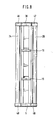
- FIG. 8 shows a view of the cabinet, with the doors 24, 26 arranged outside the housing according to the invention now being partially closed.
- the interior of the cabinet is at the bottom of the housing base 5 and the housing cover 36 at the top closed and contains two longitudinally spaced intermediate floors 19.
- the doors 24, 26 designed as rotating shells have the two bearing elements 46, 47 at the top in the area of the housing cover 36.
- the two bearing elements 48, 49 are provided at the bottom in the area of the housing base 5.
- the bearing elements 46 to 49 are arranged outside the housing and surround the housing cover 36 or housing base 5 and the housing walls.
Landscapes
- Engineering & Computer Science (AREA)
- Civil Engineering (AREA)
- Structural Engineering (AREA)
- Health & Medical Sciences (AREA)
- Public Health (AREA)
- Epidemiology (AREA)
- General Health & Medical Sciences (AREA)
- Hinges (AREA)
- Residential Or Office Buildings (AREA)
- Bathtubs, Showers, And Their Attachments (AREA)
- Magnetic Ceramics (AREA)
- Adhesives Or Adhesive Processes (AREA)
Priority Applications (1)
| Application Number | Priority Date | Filing Date | Title |
|---|---|---|---|
| AT87100218T ATE66279T1 (de) | 1986-01-21 | 1987-01-09 | Schrank, insbesondere fuer badezimmer. |
Applications Claiming Priority (2)
| Application Number | Priority Date | Filing Date | Title |
|---|---|---|---|
| DE19863601614 DE3601614A1 (de) | 1986-01-21 | 1986-01-21 | Schrank, insbesondere fuer badezimmer |
| DE3601614 | 1986-01-21 |
Publications (3)
| Publication Number | Publication Date |
|---|---|
| EP0230237A2 true EP0230237A2 (fr) | 1987-07-29 |
| EP0230237A3 EP0230237A3 (en) | 1988-07-20 |
| EP0230237B1 EP0230237B1 (fr) | 1991-08-14 |
Family
ID=6292268
Family Applications (1)
| Application Number | Title | Priority Date | Filing Date |
|---|---|---|---|
| EP87100218A Expired - Lifetime EP0230237B1 (fr) | 1986-01-21 | 1987-01-09 | Armoire, en particulier pour salle de bains |
Country Status (8)
| Country | Link |
|---|---|
| US (1) | US4783132A (fr) |
| EP (1) | EP0230237B1 (fr) |
| AT (1) | ATE66279T1 (fr) |
| AU (1) | AU592273B2 (fr) |
| CA (1) | CA1317627C (fr) |
| DE (2) | DE3601614A1 (fr) |
| GR (1) | GR3002719T3 (fr) |
| ZA (1) | ZA87360B (fr) |
Cited By (1)
| Publication number | Priority date | Publication date | Assignee | Title |
|---|---|---|---|---|
| EP0577355A1 (fr) * | 1992-07-01 | 1994-01-05 | Aqualux Products Limited | Armoires |
Families Citing this family (10)
| Publication number | Priority date | Publication date | Assignee | Title |
|---|---|---|---|---|
| FR2602410B1 (fr) * | 1986-08-11 | 1989-03-10 | Secretariat Etat Premier Minis | Casier de rangement destine en particulier aux installations sportives, ensemble de casiers, rangee de casiers et vestiaire equipe de tels casiers |
| US5458407A (en) * | 1993-04-14 | 1995-10-17 | L&P Property Management Company | Merchandising display |
| FI946052L (fi) * | 1994-12-23 | 1996-06-24 | Ido Kylpyhuone Oy | Säilytyskaappi |
| JP3097492B2 (ja) | 1995-04-17 | 2000-10-10 | 住友電気工業株式会社 | レーザ光源とその製作方法 |
| US5866876A (en) * | 1997-01-02 | 1999-02-02 | Su; Johnson | Electric oven |
| DE29711659U1 (de) * | 1997-07-03 | 1997-11-13 | Neuland GmbH Kommunikationssysteme, 36124 Eichenzell | Servierwagen |
| GB2353463A (en) * | 1999-08-25 | 2001-02-28 | Berlinlondon Ltd | Locker arrangement |
| USD473075S1 (en) | 2000-10-25 | 2003-04-15 | Federic Malle | Perfume tower |
| USD462545S1 (en) | 2000-10-25 | 2002-09-10 | Frederic Malle | 4-faceted perfume tower |
| US20050016081A1 (en) * | 2003-05-30 | 2005-01-27 | Gomree Jean Francois | Workspace habitat |
Family Cites Families (19)
| Publication number | Priority date | Publication date | Assignee | Title |
|---|---|---|---|---|
| DE160737C (fr) * | ||||
| US1033711A (en) * | 1907-03-02 | 1912-07-23 | Mfg Equipment & Engineering Company | Locker. |
| US892222A (en) * | 1907-09-09 | 1908-06-30 | John Hugh Arber | Mechanism for opening and closing doors. |
| US1702178A (en) * | 1927-12-02 | 1929-02-12 | El Paso Sash & Door Co | Telephone cabinet |
| US1934929A (en) * | 1931-03-28 | 1933-11-14 | Jonsson Arvas & Co | Transport wagons, especially for railways |
| US1874562A (en) * | 1931-05-01 | 1932-08-30 | Daprato Statuary Company | Door operating mechanism |
| US2507342A (en) * | 1947-04-30 | 1950-05-09 | Licari Vincent | Toothbrush holder |
| FR948420A (fr) * | 1947-06-09 | 1949-08-01 | Porte pivotante pour meuble métallique | |
| GB693446A (en) * | 1950-08-30 | 1953-07-01 | Harry Woolf | Improvements in or relating to wardrobes and like cabinets |
| FR2116795A5 (fr) * | 1970-12-08 | 1972-07-21 | Mazzoleni Freres | |
| US3692376A (en) * | 1970-12-17 | 1972-09-19 | Double Sixteen Co | Case for recording tape cassettes |
| DE2137914A1 (de) * | 1971-07-23 | 1973-02-15 | Bade Dieter E Dipl Ing | Abschluss fuer kleingebaeude |
| US3730468A (en) * | 1971-12-20 | 1973-05-01 | Gypsum Co | Furniture supporting system |
| US3976344A (en) * | 1972-02-11 | 1976-08-24 | Georges Frydman | Assembly system for furniture panels |
| US3826207A (en) * | 1972-08-21 | 1974-07-30 | Pickering Ind Inc | Collapsible, adjustable shelving |
| DE3067366D1 (en) * | 1979-10-17 | 1984-05-10 | Christophe Gevers | Furniture element, in particular storing cabinet, and storing unit composed of such a furniture element |
| US4288132A (en) * | 1980-02-19 | 1981-09-08 | Roper Corporation | Metal cabinet for assembly by the user from knocked-down condition |
| US4621877A (en) * | 1984-08-01 | 1986-11-11 | Digital Equipment Corporation | Securing cabinet walls |
| DE8506281U1 (de) * | 1985-03-05 | 1985-05-30 | Ninkaplast Gmbh, 4902 Bad Salzuflen | Drehbarer fachboden-einsatz fuer eckschraenke |
-
1986
- 1986-01-21 DE DE19863601614 patent/DE3601614A1/de active Granted
-
1987
- 1987-01-09 EP EP87100218A patent/EP0230237B1/fr not_active Expired - Lifetime
- 1987-01-09 DE DE8787100218T patent/DE3772060D1/de not_active Expired - Lifetime
- 1987-01-09 AT AT87100218T patent/ATE66279T1/de active
- 1987-01-14 CA CA000527351A patent/CA1317627C/fr not_active Expired - Fee Related
- 1987-01-19 ZA ZA87360A patent/ZA87360B/xx unknown
- 1987-01-21 US US07/005,869 patent/US4783132A/en not_active Expired - Fee Related
- 1987-01-21 AU AU67892/87A patent/AU592273B2/en not_active Ceased
-
1991
- 1991-09-12 GR GR91401324T patent/GR3002719T3/el unknown
Cited By (1)
| Publication number | Priority date | Publication date | Assignee | Title |
|---|---|---|---|---|
| EP0577355A1 (fr) * | 1992-07-01 | 1994-01-05 | Aqualux Products Limited | Armoires |
Also Published As
| Publication number | Publication date |
|---|---|
| DE3601614C2 (fr) | 1988-01-14 |
| EP0230237B1 (fr) | 1991-08-14 |
| EP0230237A3 (en) | 1988-07-20 |
| US4783132A (en) | 1988-11-08 |
| GR3002719T3 (en) | 1993-01-25 |
| AU592273B2 (en) | 1990-01-04 |
| ZA87360B (en) | 1987-09-30 |
| DE3601614A1 (de) | 1987-07-23 |
| ATE66279T1 (de) | 1991-08-15 |
| DE3772060D1 (de) | 1991-09-19 |
| CA1317627C (fr) | 1993-05-11 |
| AU6789287A (en) | 1987-07-23 |
Similar Documents
| Publication | Publication Date | Title |
|---|---|---|
| DE2723850C2 (de) | Möbelscharnier | |
| DE202004000652U1 (de) | Scharnier | |
| EP0384224B1 (fr) | Dispositif de guidage | |
| WO2001044608A1 (fr) | Raccord permettant de connecter deux parois minces | |
| AT401667B (de) | Möbelscharnier mit schliessmechanismus | |
| EP0230237B1 (fr) | Armoire, en particulier pour salle de bains | |
| EP0589170A1 (fr) | Ferrure de tringle de commande pour fenêtres, portes et similaires | |
| DE2739417C2 (de) | Möbelscharnier, insbesondere für Glastüren | |
| EP1497521A1 (fr) | Dispositif de fixation de ferrures de meubles a des profiles cadre d'elements de meubles en forme de plaques ou de panneaux | |
| DE3807729C2 (de) | Möbelscharnier | |
| EP0536471B1 (fr) | Plaque de moulage pour charnières de meubles | |
| AT521814A1 (de) | Möbelscharnier | |
| EP0237789B1 (fr) | Charnière de porte permettant une ouverture à 180 degrés | |
| DE2648095C2 (de) | Scharnier | |
| EP1306505A2 (fr) | Charnière, en particulier pour des portes de véhicules | |
| DE8714788U1 (de) | Faltwand für Badewannen, Duschwannen o. dgl. | |
| DE2911875A1 (de) | Aufhaengevorrichtung fuer eine verschiebbare wandtafel einer schiebetrennwand | |
| DE3223590C2 (fr) | ||
| EP1283319B1 (fr) | Paroi de séparation | |
| AT503457B1 (de) | Scharnier für die verschwenkbare anlenkung von klappen oder türflügeln am korpus von möbelstücken | |
| DE20109557U1 (de) | Innenscharnier insbesondere in einem Schaltgehäuse | |
| EP3871575A1 (fr) | Charnière | |
| EP1876319B1 (fr) | Coulisseau de guidage pour panneaux coulissants ou déplaçables selon un plan parallèle | |
| DE2647776C2 (de) | Scharnier | |
| DE2201546A1 (de) | Tuerzarge mit in die zarge eingebauten tuerbaendern |
Legal Events
| Date | Code | Title | Description |
|---|---|---|---|
| PUAI | Public reference made under article 153(3) epc to a published international application that has entered the european phase |
Free format text: ORIGINAL CODE: 0009012 |
|
| 17P | Request for examination filed |
Effective date: 19870109 |
|
| AK | Designated contracting states |
Kind code of ref document: A2 Designated state(s): AT BE CH DE ES FR GB GR IT LI NL SE |
|
| PUAL | Search report despatched |
Free format text: ORIGINAL CODE: 0009013 |
|
| AK | Designated contracting states |
Kind code of ref document: A3 Designated state(s): AT BE CH DE ES FR GB GR IT LI NL SE |
|
| RAP1 | Party data changed (applicant data changed or rights of an application transferred) |
Owner name: B.V. LEIDSE HOUTHANDEL V/H KATER EN WIETHOFF |
|
| RIN1 | Information on inventor provided before grant (corrected) |
Inventor name: BAUS, HEINZ GEORG |
|
| 17Q | First examination report despatched |
Effective date: 19890908 |
|
| RAP1 | Party data changed (applicant data changed or rights of an application transferred) |
Owner name: ALTURA LEIDEN HOLDING B.V. |
|
| RAP1 | Party data changed (applicant data changed or rights of an application transferred) |
Owner name: DUSCHOLUX GMBH Owner name: ALTURA LEIDEN HOLDING B.V. |
|
| RIN1 | Information on inventor provided before grant (corrected) | ||
| GRAA | (expected) grant |
Free format text: ORIGINAL CODE: 0009210 |
|
| AK | Designated contracting states |
Kind code of ref document: B1 Designated state(s): AT BE CH DE ES FR GB GR IT LI NL SE |
|
| PG25 | Lapsed in a contracting state [announced via postgrant information from national office to epo] |
Ref country code: GR Free format text: LAPSE BECAUSE OF FAILURE TO SUBMIT A TRANSLATION OF THE DESCRIPTION OR TO PAY THE FEE WITHIN THE PRESCRIBED TIME-LIMIT Effective date: 19910814 |
|
| REF | Corresponds to: |
Ref document number: 66279 Country of ref document: AT Date of ref document: 19910815 Kind code of ref document: T |
|
| ET | Fr: translation filed | ||
| REF | Corresponds to: |
Ref document number: 3772060 Country of ref document: DE Date of ref document: 19910919 |
|
| ITF | It: translation for a ep patent filed | ||
| PG25 | Lapsed in a contracting state [announced via postgrant information from national office to epo] |
Ref country code: ES Free format text: LAPSE BECAUSE OF FAILURE TO SUBMIT A TRANSLATION OF THE DESCRIPTION OR TO PAY THE FEE WITHIN THE PRESCRIBED TIME-LIMIT Effective date: 19911125 |
|
| GBT | Gb: translation of ep patent filed (gb section 77(6)(a)/1977) | ||
| PG25 | Lapsed in a contracting state [announced via postgrant information from national office to epo] |
Ref country code: SE Effective date: 19920110 |
|
| PG25 | Lapsed in a contracting state [announced via postgrant information from national office to epo] |
Ref country code: BE Effective date: 19920131 |
|
| PLBE | No opposition filed within time limit |
Free format text: ORIGINAL CODE: 0009261 |
|
| STAA | Information on the status of an ep patent application or granted ep patent |
Free format text: STATUS: NO OPPOSITION FILED WITHIN TIME LIMIT |
|
| BERE | Be: lapsed |
Owner name: ALTURA LEIDEN HOLDING B.V. Effective date: 19920131 |
|
| PG25 | Lapsed in a contracting state [announced via postgrant information from national office to epo] |
Ref country code: NL Effective date: 19920801 |
|
| 26N | No opposition filed | ||
| NLV4 | Nl: lapsed or anulled due to non-payment of the annual fee | ||
| REG | Reference to a national code |
Ref country code: GR Ref legal event code: FG4A Free format text: 3002719 |
|
| REG | Reference to a national code |
Ref country code: GR Ref legal event code: MM2A Free format text: 3002719 |
|
| EUG | Se: european patent has lapsed |
Ref document number: 87100218.4 Effective date: 19920806 |
|
| PGFP | Annual fee paid to national office [announced via postgrant information from national office to epo] |
Ref country code: DE Payment date: 19980313 Year of fee payment: 12 |
|
| PG25 | Lapsed in a contracting state [announced via postgrant information from national office to epo] |
Ref country code: DE Free format text: LAPSE BECAUSE OF NON-PAYMENT OF DUE FEES Effective date: 19991103 |
|
| PGFP | Annual fee paid to national office [announced via postgrant information from national office to epo] |
Ref country code: FR Payment date: 20000118 Year of fee payment: 14 |
|
| PGFP | Annual fee paid to national office [announced via postgrant information from national office to epo] |
Ref country code: AT Payment date: 20000120 Year of fee payment: 14 |
|
| PG25 | Lapsed in a contracting state [announced via postgrant information from national office to epo] |
Ref country code: AT Free format text: LAPSE BECAUSE OF NON-PAYMENT OF DUE FEES Effective date: 20010109 |
|
| PG25 | Lapsed in a contracting state [announced via postgrant information from national office to epo] |
Ref country code: FR Free format text: LAPSE BECAUSE OF NON-PAYMENT OF DUE FEES Effective date: 20010928 |
|
| REG | Reference to a national code |
Ref country code: FR Ref legal event code: ST |
|
| REG | Reference to a national code |
Ref country code: GB Ref legal event code: IF02 |
|
| REG | Reference to a national code |
Ref country code: CH Ref legal event code: PFA Owner name: ALTURA LEIDEN HOLDING B.V. Free format text: ALTURA LEIDEN HOLDING B.V.#WILHELMINASINGEL 118#MAASTRICHT (NL) -TRANSFER TO- ALTURA LEIDEN HOLDING B.V.#WILHELMINASINGEL 111#6221 BJ MAASTRICHT (NL) |
|
| PG25 | Lapsed in a contracting state [announced via postgrant information from national office to epo] |
Ref country code: IT Free format text: LAPSE BECAUSE OF NON-PAYMENT OF DUE FEES Effective date: 20050109 |
|
| PGFP | Annual fee paid to national office [announced via postgrant information from national office to epo] |
Ref country code: GB Payment date: 20060123 Year of fee payment: 20 |
|
| PGFP | Annual fee paid to national office [announced via postgrant information from national office to epo] |
Ref country code: CH Payment date: 20060124 Year of fee payment: 20 |
|
| PG25 | Lapsed in a contracting state [announced via postgrant information from national office to epo] |
Ref country code: GB Free format text: LAPSE BECAUSE OF EXPIRATION OF PROTECTION Effective date: 20070108 |
|
| REG | Reference to a national code |
Ref country code: GB Ref legal event code: PE20 |
|
| REG | Reference to a national code |
Ref country code: CH Ref legal event code: PL |