EP0230560A2 - Capteur de position - Google Patents
Capteur de position Download PDFInfo
- Publication number
- EP0230560A2 EP0230560A2 EP86116612A EP86116612A EP0230560A2 EP 0230560 A2 EP0230560 A2 EP 0230560A2 EP 86116612 A EP86116612 A EP 86116612A EP 86116612 A EP86116612 A EP 86116612A EP 0230560 A2 EP0230560 A2 EP 0230560A2
- Authority
- EP
- European Patent Office
- Prior art keywords
- signal
- sensor
- arrangement according
- evaluation circuit
- markings
- Prior art date
- Legal status (The legal status is an assumption and is not a legal conclusion. Google has not performed a legal analysis and makes no representation as to the accuracy of the status listed.)
- Granted
Links
Images


Classifications
-
- F—MECHANICAL ENGINEERING; LIGHTING; HEATING; WEAPONS; BLASTING
- F02—COMBUSTION ENGINES; HOT-GAS OR COMBUSTION-PRODUCT ENGINE PLANTS
- F02P—IGNITION, OTHER THAN COMPRESSION IGNITION, FOR INTERNAL-COMBUSTION ENGINES; TESTING OF IGNITION TIMING IN COMPRESSION-IGNITION ENGINES
- F02P7/00—Arrangements of distributors, circuit-makers or -breakers, e.g. of distributor and circuit-breaker combinations or pick-up devices
- F02P7/06—Arrangements of distributors, circuit-makers or -breakers, e.g. of distributor and circuit-breaker combinations or pick-up devices of circuit-makers or -breakers, or pick-up devices adapted to sense particular points of the timing cycle
- F02P7/067—Electromagnetic pick-up devices, e.g. providing induced current in a coil
- F02P7/0675—Electromagnetic pick-up devices, e.g. providing induced current in a coil with variable reluctance, e.g. depending on the shape of a tooth
-
- F—MECHANICAL ENGINEERING; LIGHTING; HEATING; WEAPONS; BLASTING
- F02—COMBUSTION ENGINES; HOT-GAS OR COMBUSTION-PRODUCT ENGINE PLANTS
- F02B—INTERNAL-COMBUSTION PISTON ENGINES; COMBUSTION ENGINES IN GENERAL
- F02B1/00—Engines characterised by fuel-air mixture compression
- F02B1/02—Engines characterised by fuel-air mixture compression with positive ignition
- F02B1/04—Engines characterised by fuel-air mixture compression with positive ignition with fuel-air mixture admission into cylinder
Definitions
- the invention relates to an encoder arrangement for speed detection of the crankshaft angle on the internal combustion engine according to the preamble of claim 1.
- Such sensor arrangements are used today as standard in internal combustion engines in order to deliver a cylinder signal for ignition timing controls which is in a fixed relationship to a predetermined position, for example the top dead center of a cylinder.
- Such signals are usually generated by an aperture provided on the distributor, which carries cutouts which are detected with the aid of a Hall element.
- a Hall element e.g., a Hall element
- other encoder elements such as photocells, reed relays or the like are also possible.
- Such encoder arrangements determine the position, for example, of the top dead center of a cylinder, but they are not able to generate cylinder-selective signals. To do this, it is necessary to inform the following logic in some form when the work cycle of a 720 ° crankshaft angle work sequence of an engine begins.
- the object of the invention is to provide a sensor arrangement with which a reference cylinder of the internal combustion engine can be specifically assigned to a specific crankshaft angle position.
- a sensor for detecting the marking is assigned a second sensor at a predetermined angular distance from the first sensor, and the signal from the second sensor, in comparison with the signal from the first sensor, provides information as to whether the two sensors are relative have detected short or relatively long marks on the signal transmitter.
- a relatively longer mark, which is assigned to the reference signal, can thus be discriminated against by the shorter cylinder markings.
- FIG. 1 a sensor arrangement according to the prior art is shown in supervision.
- An aperture wheel 10 has markings 12, the number corresponding to the number of cylinders of the internal combustion engine.
- a sensor or sensor 14 detects the passage of the marker 12 during the rotation of the aperture wheel 10 and emits a signal during the duration of the passage.
- FIG. 2 shows the side view of such a construction, the sensor 14 being shown as a Hall element, which detects cutouts 12 in the aperture wheel 10.
- an aperture wheel 10 is also provided which bears markings 12, each marking 12 covering an angular range ⁇ and generating a signal in passing 14 in the sensor 14, the duration of which is accordingly determined by the rotational speed of the aperture wheel 10 and the angle ⁇ .
- a marking 18 assigned to a predetermined reference cylinder differs from the other markings 12 in size. It covers an angular range that is larger by an angle ⁇ than the angle ⁇ .
- a second sensor 16 is provided, offset by an angle ⁇ to the sensor 14, which is identical in construction to the sensor 14.
- the markings are preferably provided as recesses in a with a metallic diaphragm wheel, while the sensors 14 and 16 are designed as Hall elements.
- Other pairings customary in the prior art such as openings and photocells, light sources and photocells, or phototransistors, magnets and read relays or the like can of course also be used.
- Each of the markings 12 and 18 generates a signal S1 in the sensor 14 and a signal S2 in the sensor 16.
- the signals S1 and S2 are determined in a subsequent evaluation circuit to generate the reference signal, which should only occur when the marker 18 passes by.
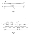
- FIG. 4 shows a first simple evaluation circuit in which the signal S1 from the sensor 14 is fed to an input 20 and the signal S2 from the sensor 16 is fed to an input 22.
- the signal 20 is tapped again at the output 24 and is used there as a speed signal, for example in order to be able to derive emergency running properties of the internal combustion engine. Since the signal S1 does not pass through any active components, a failure of the evaluation circuit does not affect the presence of the emergency operation signal.
- the evaluation circuit is essentially formed by an AND gate 28, which detects when both the signal S1 and the signal S2 are present, and in this phase a reference signal is generated at the output 26.
- the signals derived in FIG. 5 are based on an aperture wheel 10, the recess ⁇ of which corresponds to an angle of rotation of 30 ° of the camshaft and the angle ⁇ of which corresponds to an angle of 45 ° camshaft.
- the signal S1 shown in FIG. 5a is fed to one input of the NAND gate 28, the signal S2 shown in FIG. 5b is identical to the signal S1 in FIG. 5a with regard to its signal sequence, but out of phase by the angle ⁇ .
- the tuning of the angles ⁇ , ⁇ and ⁇ is such that only when the wider marking 18 passes the sensors 14 and 16 both sensors 14 and 16 simultaneously pick up a signal, as a result of which a signal occurs at the output of the NAND gate 28, which after renewed negation, can be tapped at the output as reference signal 26 and is correspondingly shown in FIG. 5c.
- FIG. 6 shows a further embodiment of the evaluation circuit which is used to convert the reference double pulse shown in FIG. 5c into a unique reference pulse.
- the signal S1 of the encoder 14 is applied to the input 20 of the circuit, the signal S2 of the encoder 18 to the input 22. As in the circuit according to FIG. 4, the signal at the input 20 is simultaneously present at the output 24 as a speed signal.
- the signal from input 20 is set to the trigger input of a D flip-flop 30, which occurs every time the rear Edge of a marker 12 or 18 runs past the sensor 14, is triggered and thus the Q output of the D flip-flop only switches to the "high” state if, at the time of the positive trigger edge, the data input previously Had “low” status.
- a pulse sequence thus arises at the output of the flip-flop, which changes to the "high” state only once per revolution of the diaphragm wheel encoder 10, specifically at the end of the slot C when its rear flank passes the sensor 14.
- the speed signal tapped at the output 24 has a different width depending on the width of the markings 12 and 18, and thus an uneven duty cycle, since it is the simple connection of the signal S1 from the encoder 14.
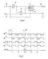
- Fig. 8 shows another evaluation circuit in which the speed signal has the same duty cycle if the angle ⁇ between the two sensors 14 and 16 is chosen equal to the angular width ⁇ of the markings A, B, D.
- an input 20 and an input 22 are provided, to which the signals S1 and S2 of the sensors 14 and 16 are fed, the reference signal is tapped at the output of the circuit 26, the speed signal at the output 24.
- a D flip-flop 36 is provided in the circuit, at the reset input of which signal S1 from input 20 is applied.
- the D input of the flip-flop 36 receives the negated signal S1, and the clock input of the flip-flop 36 is supplied with the output signal of a NAND gate 34, at whose one input the negated signal S1 tapped at the gate 32 is present and on whose other input the signal S2 is present.
- the output of this NAND gate 34 simultaneously provides the desired speed signal n at the output 24 of the evaluation circuit.
- FIG. 9a the signal S1 from sensor 14 is shown
- FIG. 9b the signal S2 from sensor 16 is shown poses.
- 9c shows the signal present at the data input of the flip-flop 36, which is the negated signal from S1, that is is. Since the signal from FIG. 9b and the signal from FIG. 9c are respectively fed to the NAND gate 34 at the inputs, the signal in FIG. 9d is the signal present at the output of the NAND gate 34, which can be used as a speed signal , the clock ratio of the signal according to FIG. 9d being constant.
- the inverted signal S1 is "low", so that the flip-flop 36 is not set by this signal when the clock input is activated.
Landscapes
- Engineering & Computer Science (AREA)
- General Engineering & Computer Science (AREA)
- Chemical & Material Sciences (AREA)
- Electromagnetism (AREA)
- Combustion & Propulsion (AREA)
- Mechanical Engineering (AREA)
- Physics & Mathematics (AREA)
- Combined Controls Of Internal Combustion Engines (AREA)
- Ignition Installations For Internal Combustion Engines (AREA)
- Transmission And Conversion Of Sensor Element Output (AREA)
- Measurement Of Length, Angles, Or The Like Using Electric Or Magnetic Means (AREA)
- Electrical Control Of Ignition Timing (AREA)
- Length Measuring Devices With Unspecified Measuring Means (AREA)
- Indicating Or Recording The Presence, Absence, Or Direction Of Movement (AREA)
Applications Claiming Priority (2)
| Application Number | Priority Date | Filing Date | Title |
|---|---|---|---|
| DE19863602292 DE3602292A1 (de) | 1986-01-25 | 1986-01-25 | Geberanordnung |
| DE3602292 | 1986-01-25 |
Publications (3)
| Publication Number | Publication Date |
|---|---|
| EP0230560A2 true EP0230560A2 (fr) | 1987-08-05 |
| EP0230560A3 EP0230560A3 (en) | 1987-11-11 |
| EP0230560B1 EP0230560B1 (fr) | 1991-01-16 |
Family
ID=6292660
Family Applications (1)
| Application Number | Title | Priority Date | Filing Date |
|---|---|---|---|
| EP86116612A Expired - Lifetime EP0230560B1 (fr) | 1986-01-25 | 1986-11-28 | Capteur de position |
Country Status (5)
| Country | Link |
|---|---|
| US (1) | US4783627A (fr) |
| EP (1) | EP0230560B1 (fr) |
| JP (1) | JPS62190408A (fr) |
| DE (2) | DE3602292A1 (fr) |
| ES (1) | ES2019580B3 (fr) |
Cited By (3)
| Publication number | Priority date | Publication date | Assignee | Title |
|---|---|---|---|---|
| FR2637652A1 (fr) * | 1988-10-11 | 1990-04-13 | Bendix Electronics Sa | Dispositif de reperage d'un cycle de fonctionnement d'un moteur a combustion interne |
| GB2234345A (en) * | 1989-06-06 | 1991-01-30 | Asahi Optical Co Ltd | Position sensing device |
| EP0879956A1 (fr) * | 1988-05-16 | 1998-11-25 | Motorola, Inc. | Capteur électronique de position associé à système de commande |
Families Citing this family (21)
| Publication number | Priority date | Publication date | Assignee | Title |
|---|---|---|---|---|
| DE3634587A1 (de) * | 1986-10-10 | 1988-04-14 | Bosch Gmbh Robert | Zuendsystem fuer verbrennungsmotoren |
| JPS63253220A (ja) * | 1987-04-10 | 1988-10-20 | Hitachi Ltd | 回転角計測装置 |
| US4972332A (en) * | 1987-07-28 | 1990-11-20 | Caterpillar Inc. | Apparatus for determining the speed, angular position and direction of rotation of a rotatable shaft |
| JPH0174376U (fr) * | 1987-11-09 | 1989-05-19 | ||
| JPH0715279B2 (ja) * | 1988-10-14 | 1995-02-22 | 三菱電機株式会社 | 点火時期制御装置 |
| EP0398909B1 (fr) * | 1988-12-09 | 1993-08-04 | Caterpillar Inc. | Appareil de determination de la vitesse, de la position angulaire et du sens de rotation d'un arbre rotatif |
| FR2650632B1 (fr) * | 1989-08-03 | 1994-04-29 | Renault Vehicules Ind | Procede et dispositif de detection pour le pilotage d'injection electronique d'un moteur multicylindre |
| WO1993009393A1 (fr) * | 1991-11-06 | 1993-05-13 | Orbital Engine Company (Australia) Pty. Limited | Procede et appareil permettant de determiner la position d'un corps se deplaçant de maniere cyclique |
| US5341097A (en) * | 1992-09-29 | 1994-08-23 | Honeywell Inc. | Asymmetrical magnetic position detector |
| US5497083A (en) * | 1992-12-24 | 1996-03-05 | Kayaba Kogyo Kabushiki Kaisha | Rod axial position detector including a first scale having equidistant magnetic parts and a second scale having unequally distant parts and differing field strengths |
| DE19520683A1 (de) | 1995-06-07 | 1996-12-12 | Teves Gmbh Alfred | Anordnung zur Erfassung einer Bewegung |
| AT2385U1 (de) * | 1997-09-09 | 1998-09-25 | Amo Automatisierung Messtechni | Winkelmesssystem |
| DE19959425A1 (de) * | 1999-12-09 | 2001-06-21 | Siemens Ag | Bewegungs-, insbesondere Drehzahl-Messeinrichtung mit erhöhter Auflösung |
| US6841962B2 (en) * | 2001-08-31 | 2005-01-11 | Package Machinery Co. Inc. | Reciprocating linear actuator |
| DE10160846A1 (de) * | 2001-12-12 | 2003-07-10 | Valeo Auto Electric Gmbh | Betätigungsvorrichtung, insbesondere zur Betätigung von Sperrdifferentialen von Fahrzeugen |
| DE102010001431A1 (de) | 2010-02-01 | 2011-08-04 | Osram Gesellschaft mit beschränkter Haftung, 81543 | Optisches System |
| DE102015209868A1 (de) * | 2015-05-29 | 2016-12-01 | Zf Friedrichshafen Ag | Planetengetriebe mit zumindest einem Sensor |
| DE102015209867A1 (de) * | 2015-05-29 | 2016-12-01 | Zf Friedrichshafen Ag | Verfahren zur Zustandsüberwachung von zumindest einem Planetenrad eines Planetengetriebes |
| DE102015209866A1 (de) * | 2015-05-29 | 2016-12-01 | Zf Friedrichshafen Ag | Verfahren zur Zustandsüberwachung von zumindest einem Planetenrad eines Planetengetriebes |
| DE102015209865B4 (de) * | 2015-05-29 | 2022-08-25 | Zf Friedrichshafen Ag | Verfahren zur Erfassung von Sensorsignalen |
| FR3083860B1 (fr) * | 2018-07-13 | 2021-01-15 | Continental Automotive France | Procede de traitement pour capteur arbre a cames |
Family Cites Families (19)
| Publication number | Priority date | Publication date | Assignee | Title |
|---|---|---|---|---|
| GB1490987A (en) * | 1974-03-08 | 1977-11-09 | Westinghouse Brake & Signal | Vehicle movement control arrangements |
| US3944923A (en) * | 1974-05-22 | 1976-03-16 | Frank Kenneth Luteran | Device for sensing the direction of motion |
| US4089316A (en) * | 1976-04-05 | 1978-05-16 | Motorola, Inc. | Adjustable rotary position sensor for electronic spark timing control |
| JPS5826339Y2 (ja) * | 1977-07-20 | 1983-06-07 | 株式会社デンソー | 回転基準位置検出装置 |
| FR2428151A1 (fr) * | 1978-06-08 | 1980-01-04 | Peugeot | Dispositif de declenchement, notamment de l'allumage d'un moteur a combustion interne |
| FR2437506A1 (fr) * | 1978-09-29 | 1980-04-25 | Thomson Csf | Capteur de position angulaire pour moteur a combustion interne equipe d'un systeme d'allumage electronique |
| DE2854017A1 (de) * | 1978-12-14 | 1980-07-03 | Bosch Gmbh Robert | Vorrichtung zur drehzahl- und drehwinkelerfassung |
| FR2445511A1 (fr) * | 1978-12-28 | 1980-07-25 | Thomson Csf | Transducteur de position pour moteur a combustion interne |
| US4280165A (en) * | 1979-04-24 | 1981-07-21 | Pospelov Boris S | Device for measuring angular position of a gear in a digital ignition system of an internal combustion engine |
| JPS5924970Y2 (ja) * | 1979-07-10 | 1984-07-23 | 株式会社デンソー | 回転位置検出装置 |
| JPS5619759U (fr) * | 1979-07-25 | 1981-02-21 | ||
| US4313414A (en) * | 1980-01-14 | 1982-02-02 | Thomson-Csf | Shaft position sensor for an internal combustion engine equipped with an electronic ignition system |
| DE3017972C2 (de) * | 1980-05-10 | 1995-01-26 | Bosch Gmbh Robert | Steuervorrichtung für mehrere Zündungs- und/oder Kraftstoffeinspritzendstufen für Brennkraftmaschinen |
| JPS5826339U (ja) * | 1981-08-17 | 1983-02-19 | 株式会社コトブキ | 折畳み式テ−ブルの甲板支持構造 |
| JPS5850257U (ja) * | 1981-09-25 | 1983-04-05 | 日本ケ−ブル・システム株式会社 | コントロ−ルケ−ブルの駆動装置 |
| JPS5870052A (ja) * | 1981-10-22 | 1983-04-26 | Kokusan Denki Co Ltd | 多気筒内燃機関用点火時期制御装置 |
| DE3220896A1 (de) * | 1982-06-03 | 1983-12-08 | Robert Bosch Gmbh, 7000 Stuttgart | Sensor |
| FR2531146B1 (fr) * | 1982-07-28 | 1986-05-16 | Peugeot | Dispositif de synchronisation pour un systeme d'allumage electronique |
| JPS59226232A (ja) * | 1983-06-06 | 1984-12-19 | Nippon Denso Co Ltd | 内燃機関用回転位置検出装置 |
-
1986
- 1986-01-25 DE DE19863602292 patent/DE3602292A1/de active Granted
- 1986-11-28 EP EP86116612A patent/EP0230560B1/fr not_active Expired - Lifetime
- 1986-11-28 DE DE8686116612T patent/DE3676990D1/de not_active Expired - Lifetime
- 1986-11-28 ES ES86116612T patent/ES2019580B3/es not_active Expired - Lifetime
-
1987
- 1987-01-26 JP JP62017124A patent/JPS62190408A/ja active Pending
- 1987-01-27 US US07/006,998 patent/US4783627A/en not_active Expired - Fee Related
Cited By (4)
| Publication number | Priority date | Publication date | Assignee | Title |
|---|---|---|---|---|
| EP0879956A1 (fr) * | 1988-05-16 | 1998-11-25 | Motorola, Inc. | Capteur électronique de position associé à système de commande |
| FR2637652A1 (fr) * | 1988-10-11 | 1990-04-13 | Bendix Electronics Sa | Dispositif de reperage d'un cycle de fonctionnement d'un moteur a combustion interne |
| GB2234345A (en) * | 1989-06-06 | 1991-01-30 | Asahi Optical Co Ltd | Position sensing device |
| US5073790A (en) * | 1989-06-06 | 1991-12-17 | Asahi Kogaku Kogyo Kabushiki Kaisha | Position sensing device |
Also Published As
| Publication number | Publication date |
|---|---|
| JPS62190408A (ja) | 1987-08-20 |
| DE3602292A1 (de) | 1987-08-06 |
| EP0230560A3 (en) | 1987-11-11 |
| ES2019580B3 (es) | 1991-07-01 |
| DE3676990D1 (de) | 1991-02-21 |
| US4783627A (en) | 1988-11-08 |
| EP0230560B1 (fr) | 1991-01-16 |
| DE3602292C2 (fr) | 1990-08-30 |
Similar Documents
| Publication | Publication Date | Title |
|---|---|---|
| EP0230560B1 (fr) | Capteur de position | |
| DE2357061C2 (de) | Einrichtung zur Abgabe von gleichmäßigen Impulsen bei bestimmten Winkelstellungen einer drehbaren Welle und zur Bildung von wenigstens einem Bezugssignal | |
| DE2326187C3 (de) | Einrichtung zur elektronischen Verstellung des Zündzeitpunktes und zur elekronischen Auslösung des Zündvorganges in Zündanlagen von Brennkraftmaschinen | |
| DE2951622C2 (fr) | ||
| DE2933516A1 (de) | Einrichtung zur drehzahlerfassung und winkelsegmenterkennung einer welle, insbesondere der kurbelwelle einer brennkraftmaschine | |
| WO1980000597A1 (fr) | Dispositif pour commander dans des machines motrices a combustion des operations qui dependent de parametres de fonctionnement et se repetent | |
| DE2645350C3 (de) | Elektronische Vorrichtung zur Zündsteuerung für Brennkraftmaschinen | |
| DE2322368B2 (de) | Vorrichtung zum verhindern des durchdrehens der antriebsraeder eines durch eine brennkraftmaschine angetriebenen kraftfahrzeuges | |
| DE2644646C2 (de) | Vorrichtung zur Erkennung eines oder mehrerer fehlender Impulse in einer sonst regelmäßigen Impulsfolge | |
| EP0745212B1 (fr) | Procede et dispositif permettant de determiner la position angulaire d'un arbre en rotation | |
| DE102010003526B4 (de) | Vorrichtung und Verfahren zur Verarbeitung von Signalen, die eine Winkelstellung einer Welle eines Motors repräsentieren | |
| DE3127220C2 (de) | Vorrichtung zum Erzeugen einer drehzahlabhängigen Signalfolge | |
| DE3034440A1 (de) | Zuendanlage fuer brennkraftmaschinen | |
| DE2614858C3 (de) | Elektronische Steuervorrichtung für die Zündung einer Brennkraftmaschine | |
| DE2703575A1 (de) | Einrichtung zum steuern des zuendzeitpunkts einer brennkraftmaschine | |
| DE69001222T2 (de) | Detektionsvorrichtung zur steuerung des elektronischen einspritzsystems einer brennkraftmaschine mit mehreren zylindern. | |
| DE19513597C2 (de) | Verfahren zur Zylindererkennung bei einer Brennkraftmaschine | |
| DE2851336C2 (fr) | ||
| DE2352941A1 (de) | Verfahren und einrichtung zur ausloesung eines impulses innerhalb eines verstellbereiches | |
| DD146325A5 (de) | Messfuehler zum messen der kolbenstellung eines mehrzylinder-verbrennungsmotors | |
| DE2648341C2 (de) | Elektronische Gebereinrichtung | |
| DE2847522A1 (de) | Induktiver geber und auswerteschaltung hierzu | |
| DE4041491C2 (de) | Sensor zur Erzeugung von elektrischen Signalen, welche die Stellung eines Objekts wiedergeben | |
| DE2325479C3 (de) | Verfahren und Vorrichtung zur drehzahlabhängigen Einstellung des Zündwinkels einer fremdgezündeten Brennkraftmaschine | |
| DE2931329C2 (fr) |
Legal Events
| Date | Code | Title | Description |
|---|---|---|---|
| PUAI | Public reference made under article 153(3) epc to a published international application that has entered the european phase |
Free format text: ORIGINAL CODE: 0009012 |
|
| 17P | Request for examination filed |
Effective date: 19861128 |
|
| AK | Designated contracting states |
Kind code of ref document: A2 Designated state(s): DE ES FR GB IT SE |
|
| PUAL | Search report despatched |
Free format text: ORIGINAL CODE: 0009013 |
|
| RHK1 | Main classification (correction) |
Ipc: F02P 7/067 |
|
| AK | Designated contracting states |
Kind code of ref document: A3 Designated state(s): DE ES FR GB IT SE |
|
| 17Q | First examination report despatched |
Effective date: 19891102 |
|
| ITF | It: translation for a ep patent filed | ||
| GRAA | (expected) grant |
Free format text: ORIGINAL CODE: 0009210 |
|
| AK | Designated contracting states |
Kind code of ref document: B1 Designated state(s): DE ES FR GB IT SE |
|
| GBT | Gb: translation of ep patent filed (gb section 77(6)(a)/1977) | ||
| REF | Corresponds to: |
Ref document number: 3676990 Country of ref document: DE Date of ref document: 19910221 |
|
| ET | Fr: translation filed | ||
| PLBI | Opposition filed |
Free format text: ORIGINAL CODE: 0009260 |
|
| 26 | Opposition filed |
Opponent name: ROBERT BOSCH GMBH Effective date: 19911015 |
|
| PGFP | Annual fee paid to national office [announced via postgrant information from national office to epo] |
Ref country code: GB Payment date: 19931021 Year of fee payment: 8 |
|
| PGFP | Annual fee paid to national office [announced via postgrant information from national office to epo] |
Ref country code: FR Payment date: 19931108 Year of fee payment: 8 |
|
| PGFP | Annual fee paid to national office [announced via postgrant information from national office to epo] |
Ref country code: SE Payment date: 19931116 Year of fee payment: 8 |
|
| PGFP | Annual fee paid to national office [announced via postgrant information from national office to epo] |
Ref country code: ES Payment date: 19931117 Year of fee payment: 8 |
|
| PGFP | Annual fee paid to national office [announced via postgrant information from national office to epo] |
Ref country code: DE Payment date: 19931210 Year of fee payment: 8 |
|
| RDAG | Patent revoked |
Free format text: ORIGINAL CODE: 0009271 |
|
| STAA | Information on the status of an ep patent application or granted ep patent |
Free format text: STATUS: PATENT REVOKED |
|
| 27W | Patent revoked |
Effective date: 19940101 |
|
| GBPR | Gb: patent revoked under art. 102 of the ep convention designating the uk as contracting state |
Free format text: 940101 |
|
| EUG | Se: european patent has lapsed |
Ref document number: 86116612.2 Effective date: 19940518 |