EP0230691A1 - Einrichtung zur Senderleistungssteuerung einer Richtfunkstrecke - Google Patents
Einrichtung zur Senderleistungssteuerung einer Richtfunkstrecke Download PDFInfo
- Publication number
- EP0230691A1 EP0230691A1 EP86202295A EP86202295A EP0230691A1 EP 0230691 A1 EP0230691 A1 EP 0230691A1 EP 86202295 A EP86202295 A EP 86202295A EP 86202295 A EP86202295 A EP 86202295A EP 0230691 A1 EP0230691 A1 EP 0230691A1
- Authority
- EP
- European Patent Office
- Prior art keywords
- received signal
- transmission power
- information
- threshold
- level
- Prior art date
- Legal status (The legal status is an assumption and is not a legal conclusion. Google has not performed a legal analysis and makes no representation as to the accuracy of the status listed.)
- Granted
Links
- 230000005540 biological transmission Effects 0.000 claims abstract description 85
- 238000005259 measurement Methods 0.000 claims abstract description 13
- 230000007423 decrease Effects 0.000 claims abstract description 11
- 230000010365 information processing Effects 0.000 claims description 9
- 238000005562 fading Methods 0.000 description 12
- 238000010586 diagram Methods 0.000 description 9
- 230000010287 polarization Effects 0.000 description 6
- 230000006835 compression Effects 0.000 description 4
- 238000007906 compression Methods 0.000 description 4
- 230000001276 controlling effect Effects 0.000 description 4
- 230000008901 benefit Effects 0.000 description 3
- 230000033228 biological regulation Effects 0.000 description 3
- 230000009849 deactivation Effects 0.000 description 3
- 238000001914 filtration Methods 0.000 description 3
- 230000006870 function Effects 0.000 description 3
- 230000000903 blocking effect Effects 0.000 description 2
- 238000001514 detection method Methods 0.000 description 2
- 230000000694 effects Effects 0.000 description 2
- 230000009467 reduction Effects 0.000 description 2
- 230000004044 response Effects 0.000 description 2
- 230000000717 retained effect Effects 0.000 description 2
- 230000008054 signal transmission Effects 0.000 description 2
- 239000007787 solid Substances 0.000 description 2
- PWNAWOCHVWERAR-UHFFFAOYSA-N Flumetralin Chemical compound [O-][N+](=O)C=1C=C(C(F)(F)F)C=C([N+]([O-])=O)C=1N(CC)CC1=C(F)C=CC=C1Cl PWNAWOCHVWERAR-UHFFFAOYSA-N 0.000 description 1
- 230000002596 correlated effect Effects 0.000 description 1
- 230000000875 corresponding effect Effects 0.000 description 1
- 238000005388 cross polarization Methods 0.000 description 1
- 230000003247 decreasing effect Effects 0.000 description 1
- 238000000034 method Methods 0.000 description 1
- 230000008569 process Effects 0.000 description 1
- 230000001105 regulatory effect Effects 0.000 description 1
- 230000003595 spectral effect Effects 0.000 description 1
- 230000001960 triggered effect Effects 0.000 description 1
Images

Classifications
-
- H—ELECTRICITY
- H04—ELECTRIC COMMUNICATION TECHNIQUE
- H04W—WIRELESS COMMUNICATION NETWORKS
- H04W52/00—Power management, e.g. Transmission Power Control [TPC] or power classes
- H04W52/04—Transmission power control [TPC]
- H04W52/18—TPC being performed according to specific parameters
- H04W52/20—TPC being performed according to specific parameters using error rate
-
- H—ELECTRICITY
- H04—ELECTRIC COMMUNICATION TECHNIQUE
- H04W—WIRELESS COMMUNICATION NETWORKS
- H04W52/00—Power management, e.g. Transmission Power Control [TPC] or power classes
- H04W52/04—Transmission power control [TPC]
- H04W52/18—TPC being performed according to specific parameters
- H04W52/24—TPC being performed according to specific parameters using SIR [Signal to Interference Ratio] or other wireless path parameters
- H04W52/245—TPC being performed according to specific parameters using SIR [Signal to Interference Ratio] or other wireless path parameters taking into account received signal strength
-
- H—ELECTRICITY
- H04—ELECTRIC COMMUNICATION TECHNIQUE
- H04W—WIRELESS COMMUNICATION NETWORKS
- H04W52/00—Power management, e.g. Transmission Power Control [TPC] or power classes
- H04W52/04—Transmission power control [TPC]
- H04W52/18—TPC being performed according to specific parameters
- H04W52/24—TPC being performed according to specific parameters using SIR [Signal to Interference Ratio] or other wireless path parameters
- H04W52/248—TPC being performed according to specific parameters using SIR [Signal to Interference Ratio] or other wireless path parameters where transmission power control commands are generated based on a path parameter
Definitions
- the present invention relates to a device for slaving the transmission power of a radio beam between at least one transmitting station and a receiving station providing information relating to the signal received at the transmitting station by means of a return channel, the servo device comprising, inter alia, at the receiving station a threshold device for measuring the received signal level providing information on the received signal level, to the transmitting station of the control means to increase or decrease the transmission power according to a given adjustment dynamic.
- Such a transmission power control device is known from the United States of America Patent No. 4,004,224, filed by the Siemens Company.
- the control of the transmission power is a function of a criterion linked to the level of the signal received.
- the choice to use this single criterion has several drawbacks.
- a first drawback appears from the fact that the quality of the received signal is not taken into account, that is to say the error rate existing in the received signal, in fact the transmission power is automatically increased to conserve a constant received signal level, even if the transmitted power value requires operation in the non-linear domain.
- the choice of this criterion is incompatible with the search for a low error rate and therefore for a high signal quality necessary for current systems.
- a second drawback is that such power regulation only takes into account the disturbances inherent in the regulated transmission channel and is ineffective in the face of disturbances due to adjacent channels.
- the present invention provides a device of the aforementioned kind which does not have the drawbacks of the known device.
- the device for controlling the transmission power of a radio beam of the type mentioned in the preamble comprises, in addition, at the receiving station a device with a threshold for measuring the rate of error of the received signal providing quality information of the received signal, which in combination with the threshold device for measuring the received signal level and by means of a combined information processing device makes it possible to apply a combined processing of the measurements of received signal level and error rate of the received signal to the transmission power control means for the control of said transmission power, the combined processing consisting in producing an increase or a decrease in the power of transmission for a first part of the dynamics taking into account only the information of the signal level received relative to a first preset threshold and for a second part of the adjustment dynamics age taking into account in addition the quality information of the received signal relative to a second preset threshold.
- a second device makes it possible to assess the quality of the signal received by measuring the error rate of the signal received and to use this quality information in combination with the level information of the signal received by the through a combined processing device to control and slave the power to the transmitting station.
- a second disadvantage relating to the use of such a criterion uniquely is that when the appearance of errors is linked to the presence of distortion in the propagation channel, blocking phenomena can occur. Indeed, the transmission power level is then increased without eliminating the errors, which has the effect of authorizing the increase in transmitted power up to the maximum value, power domain where numerous non- linearities, the number of errors increasing considerably, the device is blocked and when the error rate becomes greater than 10 -3 (commonly accepted upper limit), the transmission is then cut.
- the Applicant has managed to advantageously combine these two criteria of received level and signal quality, thereby avoiding the aforementioned drawbacks, while achieving a goal often sought in the field of radio-relay systems where the transmission is generally carried out with a margin much too large, which is to limit the power emitted.
- the combined use of these two criteria makes it possible to clearly improve the spectral efficiency and thus reduce the spacing between channels while having recourse to simple modulation equipment.
- Amplitude modulation in quadrature at 16 states allows the transmission of 140 M bit / s in a frequency plan at 40 MHz spacing at the cost of a reasonable complexity.
- the correct transmission of such modulation in radio-relay systems requires the use of linear amplifiers.
- the current solid state amplifiers are used for the transmission of signals whose average power has a drop of about 6 dB compared to the compression point 1 dB, this in order to obtain a residual error rate which is well below 10 -10 .
- the device according to the invention makes it possible to control the increase in the transmission power and thus to improve the gain of the system during the periods when the propagation fading phenomena lead to a reception level close to the threshold of the receiver.
- the gains thus obtained can be of the order of 3 dB which makes it possible to divide approximately by 2 the cut-off times which are imposed when the error rate is greater than 10 -3 .
- Figure 1 is shown a block diagram illustrating a connection between two stations 1 and 2.
- transmitting station and station 2 receiving station the signal considered being transmitted by station 1 and received by station 2. It is obvious that the description would be absolutely identical for a signal transmitted from station 2 to the station 1.
- the circuits and devices by which the signal travels in this direction of transmission described are represented in the figure in solid lines whereas in the other direction of transmission these circuits and devices, moreover identical to the first, appear in dotted lines .
- the transmission station 1 comprises, inter alia, a transmission frame device 100 followed by a modulator circuit 101 itself connected to a transmission circuit 102.
- a transmission frame device 100 At the output of the transmitter circuit 102 is connected an antenna 103 for the signal transmission.
- the signal is received by means of the antenna 200 connected to the input of the receiver circuit 201, the output of which is demodulated by means of the demodulator circuit 202, the demodulated signal is then sent to the frame device reception 203.
- the receiver circuit 201 supplies the received level measurements to the threshold device for measuring the received signal level 204 (for example a comparator circuit or a circuit known as a "Schmitt trigger") which in turn supplies logic signals in response to comparing the received signal level with a predetermined threshold.
- the threshold device for measuring the received signal level 204 (for example a comparator circuit or a circuit known as a "Schmitt trigger") which in turn supplies logic signals in response to comparing the received signal level with a predetermined threshold.
- the logic signals are then applied to the input of a multiplexer circuit 205 making it possible to multiplex in a return channel the previous information provided by the threshold circuit 204.
- the transmission of this return channel is carried out using a service multiplex channel via a service line multiplexer circuit 206, a transmission frame device 207, a modulator circuit 208, a transmitter circuit 209 and an antenna 210 which can moreover simply be the antenna 200.
- the information passing through this return channel is received at the transmitting station by means of an antenna 104 which could be the antenna 103 and a receiver circuit 105, are demodulated by a demodulator circuit 106 then are sent to a reception frame device 107 which switches the information relating to the return channel to a service line demultiplexer circuit 108 connected to a demultiplexer circuit 109 connected to the means of transmission power control 110.
- the control means 110 are those connected to the transmitter circuit 102 and receive from it the indication of the level of power transmitted.
- the output of the control means 100 is applied to the transmitter circuit 102 to control the transmission power by increasing or decreasing the transmitted power as a function of the information processed in said control means.
- the transmitter circuit 209 of the station transmits by means of the antenna 210 the signals coming from the transmission frame device 207 and from the modulator circuit 208. These signals transmitted by the station 2 are received at the station 1 by the antenna 104 and the receiver circuit 105 which is connected to a threshold device for measuring the received signal level 111 in relation to a multiplexer circuit 112 itself connected to the service line multiplexer circuit 113.
- the received signal level measurement information present at the output of the multiplexer circuit 113 are transmitted to the antenna 200 and the receiver circuit 201 via the transmission frame device 100, the modulator circuit 101 and the transmitter circuit 102 associated with the antenna 103.
- the signals at the output of the receiver circuit 201 are demodulated by the demodulator circuit 202 and pass through the reception frame device 203 which routes the information to a service line demultiplexer circuit 211 connected to a circ uit demultiplexer 212 which transmits the received signal level information to the control means of transmission power 213 connected on the other hand to the transmitter circuit 209 which thus provides them with the indication of the level of transmitted power.
- the output of the control means 213 is connected to the transmitter circuit 209 to control the transmission power.
- the device for controlling the transmission power of a radio beam between at least one transmitting station 1 and a receiving station 2 providing information relating to the signal received at the transmitting station by means of a return channel the servo device comprising, inter alia, at the receiving station a threshold device for measuring the received signal level 204 providing information on the received signal level, to the receiving station transmission of the control means 110 to increase or decrease the transmission power according to a given adjustment dynamic, is remarkable in that it further comprises, at the reception station, a device with a threshold for measuring the error rate of the received signal 214 providing quality information of the received signal, which in combination with the threshold device for measuring the received signal level 204 and by means of a combined information processing device, located at the transmitting station sion 1, makes it possible to apply a combined processing of the measurements of received signal level and of error rate of the received signal to the control means 110, of the transmission power for the control of said transmission power, the combined processing consisting in producing an increase or a decrease in the transmission power for a first part of the adjustment dynamics
- a device with a threshold for measuring the error rate of the received signal 214 (for example a compara or a circuit known as a "Schmitt trigger") is associated with the received level measurement threshold device 204.
- the inputs of this device 214 are applied on the one hand, coming from the demodulator circuit 202, the information loss of synchronization and secondly, from the frame receiving device 203 the parity divergence information.
- the output of the device 214 which thus supplies the quality information of the received signal is connected to the multiplexer circuit 205 which then performs the multiplexing of the information of the level of the received signal and of the quality of the received signal.
- the information thus multiplexed is transmitted via the various circuits and devices described above for the transmission of information relating to the level of the received signal and demultiplexed by the demultiplexer circuit 109 connected to the control means 110.
- the combined information processing device is remarkable in that it is inserted into the control means 110, it is described in FIG. 3 while a combined processing of the information is proposed in FIG. 4.
- a device with a threshold for measuring the error rate of the received signal 114 is associated with the device with a threshold for measuring the received level 111 as well as a combined information processing device is inserted in the control means 213.
- FIG. 2 provides a block diagram of devices with a threshold for measuring the level of the received signal and the quality of the signal from the receiving station 2, consequently for a direction of transmission of the information from station 1 to station 2.
- the receiver circuit 201 only appears with an IF (Intermediate Frequency) amplifier 201A and an automatic gain control circuit 201B.
- the output signal of the amplifier 201A is fed back to the circuit 201B which thus controls the gain of the amplifier 201A.
- the circuit 201B provides the measurement of the level of the signal received to the device with measurement threshold of received signal level 204 which comprises a logic threshold circuit 204A and a register 204B.
- the logic threshold circuit 204A supplies the register 204B with binary data relating to the exceeding or not exceeding of the level of the signal received relative to reference thresholds.
- An analog to digital converter can very well replace the threshold circuit 204 A.
- a logic alarm signal is emitted, when a loss of synchronization occurs at the receiving station 2, this logic signal is transmitted to the register. 204 B.
- the transmitted power level is preserved and then after a time Ta (of the order of 10 s), the transmitted power is brought back to its minimum level .
- the reception frame device 203 provides information on the divergence of the parity bit to the device with a threshold for measuring the quality of the received signal 214.
- the device 214 includes a counting circuit 214 A which makes it possible to assess the error rate by counting the number of parity divergences during a certain duration of time T.
- This duration of time or measurement window is fixed as long as the number of parity divergences is small, for example less than or equal to n1 divergences parity during T.
- Such a measurement window can be obtained for example by counting the frequency of recurrence of the frame, the closing or opening of the window for a new counting duration depending on the content of the counting circuit itself. even reset to zero on each new window. As soon as the number of divergences increases this duration becomes variable, when the counting circuit has counted n1 divergences the measurement window is closed and a new measurement window is opened for a new count.
- a logic threshold circuit 214 B When the appearance of N1 windows of reduced time duration is observed, a logic threshold circuit 214 B is activated and supplies a logic signal to the register 204 B, the error rate being greater than the predetermined threshold n1 x N1.
- the return to normal or deactivation of circuit 214 B is obtained if again in each of N2 windows of duration T the number of divergences is infer laughing or equal to a number n2, the deactivation threshold thus being equal to n2 x N2.
- the various logic signals representing the received signal level and received signal quality information are stored in the register 204 B and passed in serial mode to the multiplexer 205.
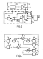
- FIG. 3 shows a block diagram of the transmission power control means, which in the direction of transmission described (from station 1 to station 2) belong to the transmission station 1 and are referenced 110 in the figure 1.
- the control means 110 produce a control signal which is applied to a controllable attenuator 102 A of the transmitter circuit 102.
- the controllable attenuator 102 A acts on the gain of an amplifier 102 B.
- the attenuator 102 A can control either the FI (Intermediate Frequency) part or the RF (Radio Frequency) part of the transmitter circuit 102, to simplify the diagram the attenuator is shown controlling the RF part, that is to say that it acts directly on the amplifier 102 B.
- the transmission power detection is carried out by means of a coupler which provides the indication of the power level transmitted to the control means 110 which receive on the other hand, the received signal level and received signal quality information at the receiving station via the demultiplexer circuit 109.
- the control means essentially consist of a digital analog converter circuit 110 A which supplies a control signal to an amplifier 110 B which also receives as a reference the indication of transmission power coming from the circuit transmitter 102, amplifier 110 B is followed by a bandpass filter 110 C, the signal at the output of the bandpass filter being the control signal from attenuator 102 A.
- the digital analog converter circuit 110 A can be realized in the form of an up-down counter which makes it possible to carry out increment or decrement steps, the steps being fixed by the weighting resistors of the converter circuit, they can be equal or variable.
- a combined information processing device is inserted in the control means.
- a combined information processing device 110 D is inserted in the control means.
- the device 110 D is preferably a programmable memory circuit (for example a PROM) in the memory of which the combined processing has been programmed which is described with FIG. 4, it can however also be produced in discrete form from logic circuits traditional.
- a logic signal depending on the transmission power level, developed from a threshold circuit 110 E which compares the indication of transmission power PE coming from the circuit transmitter 102 to typical values such as for example a minimum transmit power value PEO, a value of the high dynamic threshold of received level P1 corresponding to the high threshold of the first part of the adjustment dynamic for taking into account the only information of the received signal level, a maximum power value PMAX relative to the high threshold of the second part of the adjustment dynamics for taking into account more of the quality information of the received signal.
- typical values such as for example a minimum transmit power value PEO, a value of the high dynamic threshold of received level P1 corresponding to the high threshold of the first part of the adjustment dynamic for taking into account the only information of the received signal level, a maximum power value PMAX relative to the high threshold of the second part of the adjustment dynamics for taking into account more of the quality information of the received signal.
- the other inputs of the device 110 D are connected to the demultiplexer circuit 109 which provides the received signal level NR and signal quality information.
- the device 110 D after processing the information received controls the converter 110 A by means of two signals, an INC signal to impose an incrementation and therefore an increase in transmission power and a DEC signal to impose a decrementation and thus a reduction in transmission power.
- FIG. 4 describes a processing implemented at the transmitting station in the combined information processing device to control the increase or the decrease of the transmitting power by exploiting the information from the receiving station.
- the diagram describes the different successive states of the evolution of the combined processing of information which, according to the invention, consists in producing an increase or a decrease in the transmission power PE for a first part of the adjustment dynamics while not taking into account only that of the received signal level information NR relative to a first preset threshold S1 and for a second part of the adjustment dynamics taking into account in addition the quality information of the received signal Q relative to a second preset threshold S2.
- a first question is asked. Is the received signal level NR greater than the first preset level threshold S1? If the answer is yes, the device is in a phase of reduction and a second question is asked in state E2. Is the PE transmit power equal to the minimum allowable transmit power PEO? If the answer is yes, the transmission power can no longer be reduced, it is retained, it is state E3 and there is a return to state E1 until new responses appear on the first or on the second question. If, on the other hand, the answer is no, it is possible to further decrease the transmission power, a DEC decrement order is given by one step, this is state E4, then there is return to state E1 for possibly continue to decrease the transmit power in steps.
- state E5 the answer to the first question (is the signal level received NR lower than the pre mier preset threshold S1?) is not a third question is asked in state E5.
- the threshold P1 is the threshold not to be exceeded in the first part of the adjustment dynamics when only the level information received signal is taken into account. If the answer is yes, it is possible to increase the transmission power, an INC increment order is given by one step, it is state E5 and there is return to state E1 to possibly continue. increase the transmit power in steps. If on the other hand in state E5 the answer to the third question is no, a fourth question is asked in state E7.
- the transmission power level is kept low (much lower than the 1dB compression point) so that the amplifier non-linearities are negligible and lead to a very high residual error rate. less than 10 -10 .
- the transmission power control means increases in a step-by-step mode the transmitted power so as to maintain the received signal level value at the set value constituted by the threshold.
- the transmission power value will be limited to the value P1 located 6dB below the compression point ldB as long as the receiving station has not detected the presence of an error rate greater than the fixed threshold S2. Detection of the presence of an error rate higher than the fixed threshold then authorizes the transmission power level to increase up to the PMAX level approximately 3dB lower than the compression point 1dB (beyond the domain of strong non linearity would be reached), which has the effect of reducing the cut-off time due to propagation fading.
- One of the advantages of the device is thus achieved: making it possible to increase by approximately 3dB the power actually usable of an amplifier in the solid state used to transmit a modulation of the MAQ 16 type, during the appearance of significant propagation fading. but to keep the transmission power level low under normal propagation conditions.
- the rates of 140M bit / s in MAQ 16 modulation are transmitted on the radio-relay systems in frequency plans at 40 MHz, that is to say the spacing between two adjacent channels is 40 MHz.
- Two adjacent channels are transmitted in cross polarization (orthogonal) and benefit from a polarization decoupling of the order of 30 dB during normal propagation periods.
- XPD 45 - A
- XPD represents the polarization decoupling
- A the fading depth.
- the protection obtained is of the order of 17 to 18 dB and thus makes it possible to produce radio-relay systems which have a gross margin of 40 dB little degraded by the presence of an adjacent channel.
- the use of the device according to the invention makes it possible to use frequency plans at 30 MHz, in MAQ 16 modulation (16 states), while avoiding having to resort to more complex modulations (64 states for example).
- the adjacent channels working on crossed polarizations have a very strong correlation for fading not exceeding 10 to 15 dB and have an almost total decorrelation for deeper fading.
- the apparent loss of polarization decoupling is therefore due for the most part to the difference in signal level received between the two channels at the receiving antenna.
- Another advantage of the device according to the invention is therefore that it allows the use of 30 MHz frequency plans while retaining simple modulation equipment in MAQ 16.
- each station having a transmission part and a reception part.
- the use of the transmission power slaving device according to the invention is in no way limited to applications relating to 16-state modulation equipment.
Landscapes
- Engineering & Computer Science (AREA)
- Computer Networks & Wireless Communication (AREA)
- Signal Processing (AREA)
- Mobile Radio Communication Systems (AREA)
- Cable Transmission Systems, Equalization Of Radio And Reduction Of Echo (AREA)
- Transmitters (AREA)
- Time-Division Multiplex Systems (AREA)
- Radar Systems Or Details Thereof (AREA)
- Near-Field Transmission Systems (AREA)
- Radio Relay Systems (AREA)
Applications Claiming Priority (2)
| Application Number | Priority Date | Filing Date | Title |
|---|---|---|---|
| FR8518919A FR2592256B1 (fr) | 1985-12-20 | 1985-12-20 | Dispositif d'asservissement de la puissance d'emission d'un faisceau hertzien |
| FR8518919 | 1985-12-20 |
Publications (2)
| Publication Number | Publication Date |
|---|---|
| EP0230691A1 true EP0230691A1 (de) | 1987-08-05 |
| EP0230691B1 EP0230691B1 (de) | 1995-04-26 |
Family
ID=9326012
Family Applications (1)
| Application Number | Title | Priority Date | Filing Date |
|---|---|---|---|
| EP86202295A Expired - Lifetime EP0230691B1 (de) | 1985-12-20 | 1986-12-16 | Einrichtung zur Senderleistungssteuerung einer Richtfunkstrecke |
Country Status (9)
| Country | Link |
|---|---|
| US (1) | US4777653A (de) |
| EP (1) | EP0230691B1 (de) |
| JP (1) | JPH0795713B2 (de) |
| AU (1) | AU6665486A (de) |
| CA (1) | CA1274281A (de) |
| DE (1) | DE3650308T2 (de) |
| FI (1) | FI865149L (de) |
| FR (1) | FR2592256B1 (de) |
| NO (1) | NO865085L (de) |
Cited By (9)
| Publication number | Priority date | Publication date | Assignee | Title |
|---|---|---|---|---|
| EP0314962A3 (en) * | 1987-11-04 | 1990-09-05 | Telettra Telefonia Elettronica E Radio S.P.A. | Automatic transmit power level control in radio links |
| EP0322525A3 (en) * | 1987-12-23 | 1990-09-12 | Telettra Telefonia Elettronica E Radio S.P.A. | Automatic transmit power level control in radio links |
| EP0388894A1 (de) * | 1989-03-20 | 1990-09-26 | Fujitsu Limited | Sendeleistungsregelsystem in einem Funkgerät |
| EP0331255A3 (de) * | 1988-03-03 | 1990-11-28 | Philips Patentverwaltung GmbH | Optisches Uebertragungssystem |
| EP0527279A1 (de) * | 1990-02-28 | 1993-02-17 | AT&T Corp. | Automatische Einstellung der optischen Ausgangsleistung von mehreren optischen Sendern |
| US5199045A (en) * | 1987-06-09 | 1993-03-30 | Canon Kabushiki Kaisha | Communication apparatus |
| EP0693861A3 (de) * | 1994-07-22 | 1999-04-14 | Mitsubishi Denki Kabushiki Kaisha | Mobilkommunikationssystem |
| WO2000004649A1 (en) * | 1998-07-16 | 2000-01-27 | Nokia Networks Oy | Method for controlling transmission power in wcdma system |
| US7752488B2 (en) | 2006-01-06 | 2010-07-06 | International Business Machines Corporation | Method to adjust error thresholds in a data storage and retrieval system |
Families Citing this family (143)
| Publication number | Priority date | Publication date | Assignee | Title |
|---|---|---|---|---|
| GB2188202B (en) * | 1986-03-19 | 1989-12-06 | Marconi Co Ltd | High power systems |
| US5289459A (en) * | 1986-12-01 | 1994-02-22 | British Telecommunications Plc | Duplex data transmission |
| JPS6469127A (en) * | 1987-09-10 | 1989-03-15 | Fujitsu Ltd | High speed switching system |
| IE62238B1 (en) * | 1988-02-25 | 1995-01-11 | Dieter Stephan | Process and apparatus for producing blister packs |
| US4918431A (en) * | 1988-10-31 | 1990-04-17 | Motorola, Inc. | Method and apparatus for automatically adjusting the output power of a transmitter |
| US5003619A (en) * | 1989-01-31 | 1991-03-26 | Motorola, Inc. | Method and apparatus for adjusting the power of a transmitter |
| US4993021A (en) * | 1989-03-23 | 1991-02-12 | Telettra-Telefonia Elettronica E Radio Spa | Automatic transmit power level control in radio links |
| US4991164A (en) * | 1989-03-23 | 1991-02-05 | Telettra-Telefonia Elettronica E Radio S.P.A. | Automatic transmit power level control in radio links |
| US5485486A (en) * | 1989-11-07 | 1996-01-16 | Qualcomm Incorporated | Method and apparatus for controlling transmission power in a CDMA cellular mobile telephone system |
| US5265119A (en) * | 1989-11-07 | 1993-11-23 | Qualcomm Incorporated | Method and apparatus for controlling transmission power in a CDMA cellular mobile telephone system |
| US5267262A (en) * | 1989-11-07 | 1993-11-30 | Qualcomm Incorporated | Transmitter power control system |
| US5257283A (en) * | 1989-11-07 | 1993-10-26 | Qualcomm Incorporated | Spread spectrum transmitter power control method and system |
| GB2282734B (en) * | 1989-11-13 | 1995-08-09 | Philips Electronic Associated | Communications system |
| FI86352C (fi) * | 1989-11-14 | 1992-08-10 | Nokia Oy Ab | Digitaliskt radiolaenksystem och foerfarande foer reglering av en saendingseffekt i ett digitaliskt radiolaenksystem. |
| US5878329A (en) * | 1990-03-19 | 1999-03-02 | Celsat America, Inc. | Power control of an integrated cellular communications system |
| JP2777742B2 (ja) * | 1990-03-30 | 1998-07-23 | 株式会社小松製作所 | 光通信装置の信号伝送性能評価装置 |
| SE467332B (sv) * | 1990-06-21 | 1992-06-29 | Ericsson Telefon Ab L M | Foerfarande foer effektreglering i ett digitalt mobiltelefonisystem |
| KR950000054B1 (ko) * | 1990-07-27 | 1995-01-07 | 가부시끼가이샤 도시바 | 자동파워 콘트롤장치 |
| US5129098A (en) * | 1990-09-24 | 1992-07-07 | Novatel Communication Ltd. | Radio telephone using received signal strength in controlling transmission power |
| DE9102747U1 (de) * | 1990-12-21 | 1991-05-23 | Siemens AG, 8000 München | Verriegelungssystem, z.B. Zentralverriegelungssystem eines Kfz |
| US5204970A (en) * | 1991-01-31 | 1993-04-20 | Motorola, Inc. | Communication system capable of adjusting transmit power of a subscriber unit |
| EP0507480B1 (de) * | 1991-04-04 | 2001-06-20 | Canon Kabushiki Kaisha | Drahtlose Übertragungseinrichtung und Drucker unter Verwendung dieser Einrichtung |
| US5335360A (en) * | 1991-06-25 | 1994-08-02 | Motorola, Inc. | Base site selection apparatus and method |
| US5175871A (en) * | 1991-08-08 | 1992-12-29 | Ericsson/Ge Mobile Communication Holding Inc. | Power amplifier for a cellular telephone |
| EP0548939B1 (de) * | 1991-12-26 | 2000-09-13 | Nec Corporation | System zur Steuerung der Sendeleistung mit Gewährleistung einer konstanten Signalqualität in einem Mobilkommunikationsnetzwerk |
| KR100289630B1 (ko) * | 1992-07-13 | 2001-05-02 | 리패치 | 무선 랜의 출력제어방법 및 장치 |
| US5465399A (en) * | 1992-08-19 | 1995-11-07 | The Boeing Company | Apparatus and method for controlling transmitted power in a radio network |
| NZ255617A (en) * | 1992-09-04 | 1996-11-26 | Ericsson Telefon Ab L M | Tdma digital radio: measuring path loss and setting transmission power accordingly |
| FI96554C (fi) * | 1993-02-05 | 1996-07-10 | Nokia Mobile Phones Ltd | Aikajakoinen solukkoradiopuhelinjärjestelmä ja radiopuhelin sitä varten |
| WO1994018756A1 (en) * | 1993-02-11 | 1994-08-18 | Motorola, Inc. | Method and apparatus for controlling a power level of a subscriber unit of a wireless communication system |
| JP2937681B2 (ja) * | 1993-03-18 | 1999-08-23 | 沖電気工業株式会社 | 送信電力制御方法 |
| US5574982A (en) * | 1993-05-14 | 1996-11-12 | Telefonaktiebolaget Lm Ericsson | Method and apparatus for regulating a power level of a transmitted radio signal |
| US5669066A (en) * | 1993-05-14 | 1997-09-16 | Telefonaktiebolaget Lm Ericsson | Dynamic control of transmitting power at a transmitter and attenuation at a receiver |
| US5450617A (en) * | 1993-05-25 | 1995-09-12 | Motorola, Inc. | Method and apparatus for closed loop frequency control in a two-way communication system |
| US5465398A (en) * | 1993-10-07 | 1995-11-07 | Metricom, Inc. | Automatic power level control of a packet communication link |
| US5768684A (en) * | 1994-03-04 | 1998-06-16 | Motorola, Inc. | Method and apparatus for bi-directional power control in a digital communication system |
| US5548837A (en) * | 1994-03-28 | 1996-08-20 | Hess; Garry C. | Method and apparatus for producing diversity gain of a received signal |
| JPH07297776A (ja) * | 1994-04-22 | 1995-11-10 | Oki Electric Ind Co Ltd | 通信システム |
| US5551057A (en) * | 1994-06-08 | 1996-08-27 | Lucent Technologies Inc. | Cellular mobile radio system power control |
| US5822318A (en) * | 1994-07-29 | 1998-10-13 | Qualcomm Incorporated | Method and apparatus for controlling power in a variable rate communication system |
| GB9417318D0 (en) * | 1994-08-27 | 1994-10-19 | Philips Electronics Uk Ltd | Microwave cellular communications system and adaptable microwave transmitter |
| US5873028A (en) * | 1994-10-24 | 1999-02-16 | Ntt Mobile Communications Network Inc. | Transmission power control apparatus and method in a mobile communication system |
| FI105865B (fi) * | 1994-11-14 | 2000-10-13 | Nokia Mobile Phones Ltd | Menetelmä ja kytkentä radiolaitteen lähetinsignaalin tehon säätämiseksi ja linearisoimiseksi |
| JPH08163190A (ja) * | 1994-11-30 | 1996-06-21 | Sony Corp | 送受信機 |
| EP1104118B1 (de) * | 1994-12-13 | 2005-05-25 | NTT DoCoMo, Inc. | Sendeleistungsregelung in einem mobilen Satelliten Kommunikationssystem |
| EP0801850A1 (de) * | 1995-03-27 | 1997-10-22 | Celsat America, Inc. | Leistungsregelsystem für zellularkommunikation |
| KR0155818B1 (ko) * | 1995-04-29 | 1998-11-16 | 김광호 | 다중 반송파 전송시스템에서 적응형 전력 분배 방법 및 장치 |
| US5710981A (en) * | 1995-05-23 | 1998-01-20 | Ericsson Inc. | Portable radio power control device and method using incrementally degraded received signals |
| GB2302240B (en) * | 1995-06-02 | 2000-01-12 | Dsc Communications | Apparatus and method of frame aligning information in a wireless telecommunications system |
| US5696766A (en) * | 1995-06-02 | 1997-12-09 | Dsc Communications Corporation | Apparatus and method of synchronizing a transmitter in a subscriber terminal of a wireless telecommunications system |
| GB2301735B (en) * | 1995-06-02 | 1999-07-28 | Dsc Communications | Message handling in a telecommunications network |
| GB2301752B (en) * | 1995-06-02 | 2000-03-29 | Dsc Communications | Control message transmission in telecommunications systems |
| US5915216A (en) * | 1995-06-02 | 1999-06-22 | Dsc Communications Corporation | Apparatus and method of transmitting and receiving information in a wireless telecommunications system |
| GB2337861B (en) * | 1995-06-02 | 2000-02-23 | Dsc Communications | Integrated directional antenna |
| US5809093A (en) * | 1995-06-02 | 1998-09-15 | Dsc Communications Corporation | Apparatus and method of frame aligning information in a wireless telecommunications system |
| US5745496A (en) * | 1995-06-02 | 1998-04-28 | Dsc Communications Corporation | Apparatus and method of establishing a downlink communication path in a wireless telecommunications system |
| GB2301751B (en) * | 1995-06-02 | 2000-02-09 | Dsc Communications | Control message transmission in telecommunications systems |
| US5742595A (en) * | 1995-06-02 | 1998-04-21 | Dsc Communications Corporation | Processing CDMA signals |
| GB2301717B (en) * | 1995-06-02 | 1999-08-11 | Dsc Communications | Network controller for monitoring the status of a network |
| US6131015A (en) * | 1995-06-21 | 2000-10-10 | Motorola, Inc. | Two-way communication system for performing dynamic channel control |
| AU3260195A (en) * | 1995-08-31 | 1997-03-19 | Nokia Telecommunications Oy | Method and device for controlling transmission power of a radio transmitter in a cellular communication system |
| US5790533A (en) * | 1995-10-27 | 1998-08-04 | Motorola, Inc. | Method and apparatus for adaptive RF power control of cable access units |
| US5722051A (en) * | 1996-02-13 | 1998-02-24 | Lucent Technologies Inc. | Adaptive power control and coding scheme for mobile radio systems |
| SE515509C2 (sv) * | 1996-04-29 | 2001-08-20 | Radio Design Innovation Tj Ab | Adaptivt luftgränssnitt |
| US5774785A (en) * | 1996-06-20 | 1998-06-30 | Telefonaktiebolaget Lm Ericsson | Adaptive quality adjustment |
| KR100309652B1 (ko) | 1996-06-27 | 2001-12-17 | 다치카와 게이지 | 송신전력제어장치 |
| JPH1041896A (ja) * | 1996-07-19 | 1998-02-13 | Sony Corp | 送受信装置および送受信方法 |
| US5960361A (en) * | 1996-10-22 | 1999-09-28 | Qualcomm Incorporated | Method and apparatus for performing a fast downward move in a cellular telephone forward link power control system |
| JP2861970B2 (ja) * | 1996-10-23 | 1999-02-24 | 日本電気株式会社 | 通信システム |
| US6075974A (en) * | 1996-11-20 | 2000-06-13 | Qualcomm Inc. | Method and apparatus for adjusting thresholds and measurements of received signals by anticipating power control commands yet to be executed |
| US5956619A (en) * | 1996-12-12 | 1999-09-21 | Globalstar L.P. | Satellite controlled power control for personal communication user terminals |
| USRE39177E1 (en) * | 1997-01-29 | 2006-07-11 | Qualcomm, Inc. | Method and apparatus for performing soft hand-off in a wireless communication system |
| US6151502A (en) * | 1997-01-29 | 2000-11-21 | Qualcomm Incorporated | Method and apparatus for performing soft hand-off in a wireless communication system |
| US5933781A (en) * | 1997-01-31 | 1999-08-03 | Qualcomm Incorporated | Pilot based, reversed channel power control |
| US5987326A (en) * | 1997-02-11 | 1999-11-16 | Qualcomm Incorporated | Transmit power reduction for a high speed CDMA link in soft handoff |
| CN1510937B (zh) * | 1997-04-17 | 2013-05-22 | Ntt移动通信网株式会社 | 通信系统中的通信方法和通信装置中的通信方法 |
| US6396867B1 (en) | 1997-04-25 | 2002-05-28 | Qualcomm Incorporated | Method and apparatus for forward link power control |
| US6002933A (en) * | 1997-04-29 | 1999-12-14 | Qualcomm Incorporated | Inter-system soft handoff |
| US6072990A (en) * | 1997-05-08 | 2000-06-06 | Lucent Technologies, Inc. | Transmitter-receiver pair for wireless network power-code operating point is determined based on error rate |
| US5982760A (en) * | 1997-06-20 | 1999-11-09 | Qualcomm Inc. | Method and apparatus for power adaptation control in closed-loop communications |
| US6426960B2 (en) | 1997-06-24 | 2002-07-30 | Qualcomm Incorporated | Increased capacity data transmission in a CDMA wireless communication system |
| KR100259839B1 (ko) * | 1997-06-30 | 2000-06-15 | 윤종용 | 삭제 지시자 비트를 이용한 순방향 전력 제어 방법 |
| US6055428A (en) * | 1997-07-21 | 2000-04-25 | Qualcomm Incorporated | Method and apparatus for performing soft hand-off in a wireless communication system |
| US6188678B1 (en) | 1997-08-07 | 2001-02-13 | Qualcomm Inc. | Method and apparatus for adaptive closed loop power control using open loop measurements |
| US6147981A (en) * | 1997-08-07 | 2000-11-14 | Qualcomm Incorporated | Method and apparatus for predictive parameter control with loop delay |
| US6070085A (en) | 1997-08-12 | 2000-05-30 | Qualcomm Inc. | Method and apparatus for controlling transmit power thresholds based on classification of wireless communication subscribers |
| US6101179A (en) * | 1997-09-19 | 2000-08-08 | Qualcomm Incorporated | Accurate open loop power control in a code division multiple access communication system |
| US5987333A (en) * | 1997-09-30 | 1999-11-16 | Nortel Networks Corporation/Corporation Nortel Networks | Communications power control |
| US6711415B1 (en) * | 1997-10-03 | 2004-03-23 | Nortel Networks Limited | Method and system for minimizing transmitter power levels within a cellular telephone communications network |
| US6269093B1 (en) * | 1997-12-16 | 2001-07-31 | Nokia Mobile Phones Limited | Adaptive removal of disturbance in TDMA acoustic peripheral devices |
| US6298220B1 (en) * | 1998-01-15 | 2001-10-02 | Hughes Electronics Corporation | Power control system for communications channels |
| US6104512A (en) * | 1998-01-23 | 2000-08-15 | Motorola, Inc. | Method for adjusting the power level of an infrared signal |
| JP3299927B2 (ja) * | 1998-01-29 | 2002-07-08 | 沖電気工業株式会社 | 移動体通信システム、および移動局の位置推定方法 |
| US6236726B1 (en) * | 1998-02-27 | 2001-05-22 | Nortel Networks Limited | Transmit power scaling for far-end crosstalk reduction |
| US6070074A (en) * | 1998-04-24 | 2000-05-30 | Trw Inc. | Method for enhancing the performance of a regenerative satellite communications system |
| JPH11355204A (ja) * | 1998-06-04 | 1999-12-24 | Nec Corp | Cdma移動通信システム及びcdma移動通信システムにおける送信電力制御方法 |
| WO2000007318A1 (en) | 1998-07-30 | 2000-02-10 | Airnet Communications Corporation | Broadband power management (power banking) within a broadband multi-carrier base station transceiver system |
| US6590682B1 (en) * | 1998-08-10 | 2003-07-08 | Zilog, Inc. | Infrared signal communication system and method including transmission means having automatic gain control |
| US6519236B1 (en) | 1998-09-18 | 2003-02-11 | Telefonaktiebolaget Lm Ericsson (Publ) | Automatic power control in uncoordinated frequency-hopping radio systems |
| AU6162799A (en) * | 1998-09-29 | 2000-04-17 | Triton Network Systems, Inc. | System and method of controlling co-channel interference in point to point communications |
| US6512925B1 (en) * | 1998-12-03 | 2003-01-28 | Qualcomm, Incorporated | Method and apparatus for controlling transmission power while in soft handoff |
| US6788685B1 (en) | 1999-01-28 | 2004-09-07 | Qualcomm, Incorporated | Method and apparatus for controlling transmission power in a CDMA communication system |
| US6373823B1 (en) | 1999-01-28 | 2002-04-16 | Qualcomm Incorporated | Method and apparatus for controlling transmission power in a potentially transmission gated or capped communication system |
| DE19911146C2 (de) * | 1999-03-12 | 2003-10-02 | Siemens Ag | Verfahren zur Sendeleistungsregelung in einem Funk-Kommunikationssystem |
| US6802033B1 (en) | 1999-04-06 | 2004-10-05 | International Business Machines Corporation | Low-power critical error rate communications controller |
| US6249683B1 (en) | 1999-04-08 | 2001-06-19 | Qualcomm Incorporated | Forward link power control of multiple data streams transmitted to a mobile station using a common power control channel |
| JP2000307520A (ja) * | 1999-04-26 | 2000-11-02 | Sony Corp | 光送受信装置及び光送受信方法 |
| US6690938B1 (en) | 1999-05-06 | 2004-02-10 | Qualcomm Incorporated | System and method for reducing dropped calls in a wireless communications network |
| US6351460B1 (en) * | 1999-05-24 | 2002-02-26 | Qualcomm Incorporated | Method and apparatus for a dedicated control channel in an early soft handoff in a code division multiple access communication system |
| US7649925B2 (en) * | 1999-06-14 | 2010-01-19 | Time Domain Corporation | Time transfer utilizing ultra wideband signals |
| US6539213B1 (en) | 1999-06-14 | 2003-03-25 | Time Domain Corporation | System and method for impulse radio power control |
| GB2351420A (en) * | 1999-06-23 | 2000-12-27 | Motorola Ltd | Power control in a radio communication system |
| JP2001077714A (ja) * | 1999-09-03 | 2001-03-23 | Matsushita Electric Ind Co Ltd | 無線受信機、無線受信方法および記録媒体 |
| US6487241B1 (en) | 1999-11-22 | 2002-11-26 | Advanced Micro Devices, Inc. | Method and apparatus employing cutback probe |
| US6687509B2 (en) | 1999-12-29 | 2004-02-03 | Airnet Communications Corporation | Backhaul power control system in a wireless repeater |
| GB2358328A (en) * | 2000-01-14 | 2001-07-18 | Motorola Ltd | Power control in Mobile communications |
| US6678530B1 (en) * | 2000-05-18 | 2004-01-13 | Denso Corporation | Dynamic power control of a channel signal |
| US7801544B2 (en) | 2001-06-29 | 2010-09-21 | Koninklijke Philips Electronics N.V. | Noise margin information for power control and link adaptation in IEEE 802.11h WLAN |
| USRE47911E1 (en) | 2001-06-29 | 2020-03-17 | Koninklijke Philips N.V. | Noise margin information for power control and link adaptation in IEEE 802.11h WLAN |
| US6665283B2 (en) * | 2001-08-10 | 2003-12-16 | Motorola, Inc. | Method and apparatus for transmitting data in a packet data communication system |
| DE10150476A1 (de) * | 2001-10-16 | 2003-04-17 | Thomson Brandt Gmbh | Wireless LAN |
| KR100469245B1 (ko) * | 2001-12-07 | 2005-02-02 | 엘지전자 주식회사 | 순방향 링크 전력 제어 방법 |
| EP1525678B1 (de) * | 2002-06-21 | 2008-07-30 | QUALCOMM Incorporated | Zwischenverstärker für drahtlose lokale netzwerke |
| US8885688B2 (en) | 2002-10-01 | 2014-11-11 | Qualcomm Incorporated | Control message management in physical layer repeater |
| US8122134B2 (en) * | 2002-10-11 | 2012-02-21 | Qualcomm Incorporated | Reducing loop effects in a wireless local area network repeater |
| US8078100B2 (en) * | 2002-10-15 | 2011-12-13 | Qualcomm Incorporated | Physical layer repeater with discrete time filter for all-digital detection and delay generation |
| EP1604468B1 (de) | 2002-10-15 | 2008-07-23 | Qualcomm Incorporated | Wlan-repeater mit automatischer verstärkungsregelung für erweiterte netzabdeckung |
| US7230935B2 (en) | 2002-10-24 | 2007-06-12 | Widefi, Inc. | Physical layer repeater with selective use of higher layer functions based on network operating conditions |
| CN100588133C (zh) | 2002-11-15 | 2010-02-03 | 高通股份有限公司 | 检测信号存在的方法和装置 |
| GB2396004B (en) * | 2002-12-06 | 2006-02-22 | Optex Co Ltd | Anti-thief security sensor assembly with variable amount of emitted infrared beam |
| JP2006510326A (ja) | 2002-12-16 | 2006-03-23 | ワイデファイ インコーポレイテッド | 改良された無線ネットワーク中継器 |
| JP2006514453A (ja) * | 2003-01-31 | 2006-04-27 | ノキア コーポレイション | マルチスロットアップリンクのための出力電力制御 |
| US20060182030A1 (en) * | 2003-05-05 | 2006-08-17 | Harris John M | Method and apparatus for transmitting data in a packet data communication |
| US8027642B2 (en) | 2004-04-06 | 2011-09-27 | Qualcomm Incorporated | Transmission canceller for wireless local area network |
| CN1993904B (zh) * | 2004-05-13 | 2011-09-07 | 高通股份有限公司 | 具有用于上行链路及下行链路同步之下行链路检测的非变频中继器 |
| CN1985528B (zh) | 2004-06-03 | 2010-06-09 | 高通股份有限公司 | 具有低成本高性能本振架构的变频中继器 |
| US8059727B2 (en) | 2005-01-28 | 2011-11-15 | Qualcomm Incorporated | Physical layer repeater configuration for increasing MIMO performance |
| JP5199261B2 (ja) | 2006-09-21 | 2013-05-15 | クゥアルコム・インコーポレイテッド | リピータの間の振動を緩和するための方法および装置 |
| US8774079B2 (en) * | 2006-10-26 | 2014-07-08 | Qualcomm Incorporated | Repeater techniques for multiple input multiple output utilizing beam formers |
| JP5125368B2 (ja) * | 2007-09-28 | 2013-01-23 | 富士通セミコンダクター株式会社 | 半導体装置、通信システム及び送受信振幅最適化方法、 |
| EP2830382B1 (de) * | 2013-07-23 | 2016-03-23 | Alcatel Lucent | Verfahren zur drahtlosen Backhaul Kommunikation, Funkzugriffseinheit und zentrale Einheit dafür |
| US9667312B2 (en) * | 2015-01-13 | 2017-05-30 | Hughes Network Systems, Llc | Radio based automatic level control for linear radio calibration |
| JP7593153B2 (ja) * | 2021-01-29 | 2024-12-03 | オムロン株式会社 | ネットワークシステム |
Citations (2)
| Publication number | Priority date | Publication date | Assignee | Title |
|---|---|---|---|---|
| US4361892A (en) * | 1980-11-03 | 1982-11-30 | Bell Telephone Laboratories, Incorporated | Adaptive equalizer |
| EP0115139A2 (de) * | 1982-12-27 | 1984-08-08 | Western Electric Company, Incorporated | Funkübertragungsgeräte und -systeme |
Family Cites Families (9)
| Publication number | Priority date | Publication date | Assignee | Title |
|---|---|---|---|---|
| US4004224A (en) | 1972-01-17 | 1977-01-18 | Siemens Aktiengesellschaft | Method for fade correction of communication transmission over directional radio paths |
| US4309771A (en) * | 1979-07-02 | 1982-01-05 | Farinon Corporation | Digital radio transmission system |
| JPS56122246A (en) * | 1980-02-29 | 1981-09-25 | Fujitsu Ltd | Control system of transmission output |
| JPS5913429A (ja) * | 1982-07-15 | 1984-01-24 | Nippon Telegr & Teleph Corp <Ntt> | 無線通信装置 |
| JPS609230A (ja) * | 1983-06-28 | 1985-01-18 | Nec Corp | 送信電力制御方式 |
| US4639936A (en) * | 1984-02-10 | 1987-01-27 | Prime Computer, Inc. | Data transmission signal apparatus |
| US4619002A (en) * | 1984-07-02 | 1986-10-21 | Motorola, Inc. | Self-calibrating signal strength detector |
| SE445698B (sv) * | 1984-11-19 | 1986-07-07 | Ericsson Telefon Ab L M | Forfarande att reducera smalbandiga storares inverkan vid radiokommunikation mellan tva stationer, vilka utnyttjar frekvenshopp |
| DE3513361A1 (de) * | 1985-04-15 | 1986-10-16 | Philips Patentverwaltung Gmbh, 2000 Hamburg | Verfahren und schaltungsanordnung zur qualitaetsmessung von funkuebertragungskanaelen eines funkuebertragungssystems |
-
1985
- 1985-12-20 FR FR8518919A patent/FR2592256B1/fr not_active Expired
-
1986
- 1986-12-11 US US06/940,325 patent/US4777653A/en not_active Expired - Fee Related
- 1986-12-16 EP EP86202295A patent/EP0230691B1/de not_active Expired - Lifetime
- 1986-12-16 NO NO865085A patent/NO865085L/no unknown
- 1986-12-16 DE DE3650308T patent/DE3650308T2/de not_active Expired - Fee Related
- 1986-12-17 AU AU66654/86A patent/AU6665486A/en not_active Abandoned
- 1986-12-17 FI FI865149A patent/FI865149L/fi not_active Application Discontinuation
- 1986-12-17 CA CA000525626A patent/CA1274281A/en not_active Expired - Lifetime
- 1986-12-18 JP JP61300171A patent/JPH0795713B2/ja not_active Expired - Lifetime
Patent Citations (2)
| Publication number | Priority date | Publication date | Assignee | Title |
|---|---|---|---|---|
| US4361892A (en) * | 1980-11-03 | 1982-11-30 | Bell Telephone Laboratories, Incorporated | Adaptive equalizer |
| EP0115139A2 (de) * | 1982-12-27 | 1984-08-08 | Western Electric Company, Incorporated | Funkübertragungsgeräte und -systeme |
Cited By (10)
| Publication number | Priority date | Publication date | Assignee | Title |
|---|---|---|---|---|
| US5199045A (en) * | 1987-06-09 | 1993-03-30 | Canon Kabushiki Kaisha | Communication apparatus |
| EP0314962A3 (en) * | 1987-11-04 | 1990-09-05 | Telettra Telefonia Elettronica E Radio S.P.A. | Automatic transmit power level control in radio links |
| EP0322525A3 (en) * | 1987-12-23 | 1990-09-12 | Telettra Telefonia Elettronica E Radio S.P.A. | Automatic transmit power level control in radio links |
| EP0331255A3 (de) * | 1988-03-03 | 1990-11-28 | Philips Patentverwaltung GmbH | Optisches Uebertragungssystem |
| EP0388894A1 (de) * | 1989-03-20 | 1990-09-26 | Fujitsu Limited | Sendeleistungsregelsystem in einem Funkgerät |
| EP0527279A1 (de) * | 1990-02-28 | 1993-02-17 | AT&T Corp. | Automatische Einstellung der optischen Ausgangsleistung von mehreren optischen Sendern |
| EP0693861A3 (de) * | 1994-07-22 | 1999-04-14 | Mitsubishi Denki Kabushiki Kaisha | Mobilkommunikationssystem |
| WO2000004649A1 (en) * | 1998-07-16 | 2000-01-27 | Nokia Networks Oy | Method for controlling transmission power in wcdma system |
| US6792248B1 (en) | 1998-07-16 | 2004-09-14 | Nokia Networks Oy | Method for controlling transmission power in WCDMA system |
| US7752488B2 (en) | 2006-01-06 | 2010-07-06 | International Business Machines Corporation | Method to adjust error thresholds in a data storage and retrieval system |
Also Published As
| Publication number | Publication date |
|---|---|
| JPS62157427A (ja) | 1987-07-13 |
| EP0230691B1 (de) | 1995-04-26 |
| FI865149A7 (fi) | 1987-06-21 |
| FI865149L (fi) | 1987-06-21 |
| FR2592256A1 (fr) | 1987-06-26 |
| AU6665486A (en) | 1987-06-25 |
| DE3650308D1 (de) | 1995-06-01 |
| DE3650308T2 (de) | 1995-11-16 |
| JPH0795713B2 (ja) | 1995-10-11 |
| NO865085D0 (no) | 1986-12-16 |
| NO865085L (no) | 1987-06-22 |
| CA1274281A (en) | 1990-09-18 |
| US4777653A (en) | 1988-10-11 |
| FI865149A0 (fi) | 1986-12-17 |
| FR2592256B1 (fr) | 1988-02-12 |
Similar Documents
| Publication | Publication Date | Title |
|---|---|---|
| EP0230691B1 (de) | Einrichtung zur Senderleistungssteuerung einer Richtfunkstrecke | |
| US7356256B1 (en) | Digital performance monitoring for an optical communications system | |
| US7813655B2 (en) | Signal waveform deterioration compensator | |
| WO1993006677A1 (fr) | Procede de transmission numerique et recepteur a conversion directe | |
| EP0016705B1 (de) | R.F.Stufe mit automatischer Verstärkungsregelung und Empfänger mit einer solchen Stufe | |
| FR2811776A1 (fr) | Emetteur optique et systeme de transmission optique | |
| FR2576472A1 (fr) | Procede et dispositif de commande automatique de gain d'un recepteur en acces multiple a repartition temporelle | |
| EP0971494A1 (de) | Quasi-verteilte Verstärkung in einer Soliton-WDM Übertragung | |
| FR2496363A1 (fr) | Procede et dispositif de detection de la sequence d'apprentissage d'un egaliseur auto-adaptatif | |
| FR2598872A1 (fr) | Systeme de demodulation de signal numerique | |
| FR2580130A1 (de) | ||
| US5572350A (en) | Method and apparatus to compensate for differential attenuation in an optical time slot interchanger | |
| EP0756390A1 (de) | Verfahren zur Leistungsregelung in einem Kommunikationssystem | |
| US20180069636A1 (en) | Hybrid Direct-Detection Differential Phase Shift Keying-Multipulse Pulse Position Modulation Techniques for Optical Communication Systems | |
| US20210135765A1 (en) | Optical receiver, light signal receiving method, and data reproduction device | |
| FR2687876A1 (fr) | Ensemble de detection d'erreurs pour ligne de transmission numerique et procede de surveillance. | |
| CN115499066A (zh) | 光信号的接收装置、终端、系统及方法 | |
| FR2843503A1 (fr) | Procede de reglage pour recepteur de signaux transmis par salves et recepteurs correspondants | |
| US20150200724A1 (en) | Correction table for interferometric optical signal-to-noise ration monitor | |
| FR2565445A1 (fr) | Demodulateur de frequence et recepteur d'emission de television a multiplexage temporel en comportant application | |
| EP0428444A1 (de) | Verfahren zur Synchronisationssuche beim Empfang eines Spreizspektrumsignals | |
| EP0089276A1 (de) | Taktfrequenzwiedergewinnungseinrichtung für digitale Übertragung | |
| EP0604295A1 (de) | Verfahren zur Verstärkungsregelung in einem digitalen Empfänger, insbesondere einem TDMA-Empfänger und Vorrichtung zur Durchführung des Verfahrens | |
| FR2811831A1 (fr) | Procede et dispositif de conversion analogique/numerique | |
| EP1206045A1 (de) | Verfahren zum Korrigieren der Frequenzfehler |
Legal Events
| Date | Code | Title | Description |
|---|---|---|---|
| PUAI | Public reference made under article 153(3) epc to a published international application that has entered the european phase |
Free format text: ORIGINAL CODE: 0009012 |
|
| AK | Designated contracting states |
Kind code of ref document: A1 Designated state(s): BE CH DE FR GB IT LI NL SE |
|
| 17P | Request for examination filed |
Effective date: 19871118 |
|
| 17Q | First examination report despatched |
Effective date: 19900320 |
|
| RAP1 | Party data changed (applicant data changed or rights of an application transferred) |
Owner name: TRT TELECOMMUNICATIONS RADIOELECTRIQUES ET TELEPH Owner name: TELECOMMUNICATIONS RADIOELECTRIQUES ET TELEPHONIQU |
|
| RAP1 | Party data changed (applicant data changed or rights of an application transferred) |
Owner name: TRT TELECOMMUNICATIONS RADIOELECTRIQUES ET TELEPH Owner name: TELECOMMUNICATIONS RADIOELECTRIQUES ET TELEPHONIQU |
|
| RAP1 | Party data changed (applicant data changed or rights of an application transferred) |
Owner name: TRT TELECOMMUNICATIONS RADIOELECTRIQUES ET TELEPHO |
|
| GRAA | (expected) grant |
Free format text: ORIGINAL CODE: 0009210 |
|
| AK | Designated contracting states |
Kind code of ref document: B1 Designated state(s): BE CH DE FR GB IT LI NL SE |
|
| PG25 | Lapsed in a contracting state [announced via postgrant information from national office to epo] |
Ref country code: NL Free format text: LAPSE BECAUSE OF FAILURE TO SUBMIT A TRANSLATION OF THE DESCRIPTION OR TO PAY THE FEE WITHIN THE PRESCRIBED TIME-LIMIT Effective date: 19950426 |
|
| REF | Corresponds to: |
Ref document number: 3650308 Country of ref document: DE Date of ref document: 19950601 |
|
| ITF | It: translation for a ep patent filed | ||
| PG25 | Lapsed in a contracting state [announced via postgrant information from national office to epo] |
Ref country code: SE Effective date: 19950726 |
|
| GBT | Gb: translation of ep patent filed (gb section 77(6)(a)/1977) |
Effective date: 19950703 |
|
| NLV1 | Nl: lapsed or annulled due to failure to fulfill the requirements of art. 29p and 29m of the patents act | ||
| PLBE | No opposition filed within time limit |
Free format text: ORIGINAL CODE: 0009261 |
|
| STAA | Information on the status of an ep patent application or granted ep patent |
Free format text: STATUS: NO OPPOSITION FILED WITHIN TIME LIMIT |
|
| PGFP | Annual fee paid to national office [announced via postgrant information from national office to epo] |
Ref country code: CH Payment date: 19960322 Year of fee payment: 10 |
|
| 26N | No opposition filed | ||
| REG | Reference to a national code |
Ref country code: FR Ref legal event code: TP |
|
| REG | Reference to a national code |
Ref country code: CH Ref legal event code: PUE Owner name: TELECOMMUNICATIONS RADIOELECTRIQUES ET TELEPHONIQU Ref country code: CH Ref legal event code: NV Representative=s name: ISLER & PEDRAZZINI AG PATENTANWAELTE |
|
| REG | Reference to a national code |
Ref country code: GB Ref legal event code: 732E |
|
| PGFP | Annual fee paid to national office [announced via postgrant information from national office to epo] |
Ref country code: GB Payment date: 19961202 Year of fee payment: 11 |
|
| PGFP | Annual fee paid to national office [announced via postgrant information from national office to epo] |
Ref country code: BE Payment date: 19961204 Year of fee payment: 11 |
|
| PGFP | Annual fee paid to national office [announced via postgrant information from national office to epo] |
Ref country code: FR Payment date: 19961217 Year of fee payment: 11 |
|
| PG25 | Lapsed in a contracting state [announced via postgrant information from national office to epo] |
Ref country code: LI Effective date: 19961231 Ref country code: CH Effective date: 19961231 |
|
| PGFP | Annual fee paid to national office [announced via postgrant information from national office to epo] |
Ref country code: DE Payment date: 19970221 Year of fee payment: 11 |
|
| REG | Reference to a national code |
Ref country code: CH Ref legal event code: PL |
|
| REG | Reference to a national code |
Ref country code: FR Ref legal event code: TP |
|
| REG | Reference to a national code |
Ref country code: GB Ref legal event code: 732E |
|
| PG25 | Lapsed in a contracting state [announced via postgrant information from national office to epo] |
Ref country code: GB Free format text: LAPSE BECAUSE OF NON-PAYMENT OF DUE FEES Effective date: 19971216 |
|
| PG25 | Lapsed in a contracting state [announced via postgrant information from national office to epo] |
Ref country code: FR Free format text: THE PATENT HAS BEEN ANNULLED BY A DECISION OF A NATIONAL AUTHORITY Effective date: 19971231 Ref country code: BE Free format text: LAPSE BECAUSE OF NON-PAYMENT OF DUE FEES Effective date: 19971231 |
|
| BERE | Be: lapsed |
Owner name: PHILIPS ELECTRONICS N.V. Effective date: 19971231 |
|
| GBPC | Gb: european patent ceased through non-payment of renewal fee |
Effective date: 19971216 |
|
| PG25 | Lapsed in a contracting state [announced via postgrant information from national office to epo] |
Ref country code: DE Free format text: LAPSE BECAUSE OF NON-PAYMENT OF DUE FEES Effective date: 19980901 |
|
| REG | Reference to a national code |
Ref country code: FR Ref legal event code: ST |
|
| APAH | Appeal reference modified |
Free format text: ORIGINAL CODE: EPIDOSCREFNO |
|
| PG25 | Lapsed in a contracting state [announced via postgrant information from national office to epo] |
Ref country code: IT Free format text: LAPSE BECAUSE OF NON-PAYMENT OF DUE FEES;WARNING: LAPSES OF ITALIAN PATENTS WITH EFFECTIVE DATE BEFORE 2007 MAY HAVE OCCURRED AT ANY TIME BEFORE 2007. THE CORRECT EFFECTIVE DATE MAY BE DIFFERENT FROM THE ONE RECORDED. Effective date: 20051216 |