EP0230713A2 - Baguette décorative sans substrat et son mode de fabrication - Google Patents
Baguette décorative sans substrat et son mode de fabrication Download PDFInfo
- Publication number
- EP0230713A2 EP0230713A2 EP86307029A EP86307029A EP0230713A2 EP 0230713 A2 EP0230713 A2 EP 0230713A2 EP 86307029 A EP86307029 A EP 86307029A EP 86307029 A EP86307029 A EP 86307029A EP 0230713 A2 EP0230713 A2 EP 0230713A2
- Authority
- EP
- European Patent Office
- Prior art keywords
- layer
- adhesive
- pressure sensitive
- sensitive adhesive
- plastic
- Prior art date
- Legal status (The legal status is an assumption and is not a legal conclusion. Google has not performed a legal analysis and makes no representation as to the accuracy of the status listed.)
- Granted
Links
Images

Classifications
-
- B—PERFORMING OPERATIONS; TRANSPORTING
- B44—DECORATIVE ARTS
- B44C—PRODUCING DECORATIVE EFFECTS; MOSAICS; TARSIA WORK; PAPERHANGING
- B44C1/00—Processes, not specifically provided for elsewhere, for producing decorative surface effects
- B44C1/10—Applying flat materials, e.g. leaflets, pieces of fabrics
- B44C1/105—Applying flat materials, e.g. leaflets, pieces of fabrics comprising an adhesive layer
-
- B—PERFORMING OPERATIONS; TRANSPORTING
- B44—DECORATIVE ARTS
- B44C—PRODUCING DECORATIVE EFFECTS; MOSAICS; TARSIA WORK; PAPERHANGING
- B44C3/00—Processes, not specifically provided for elsewhere, for producing ornamental structures
- B44C3/02—Superimposing layers
-
- B—PERFORMING OPERATIONS; TRANSPORTING
- B44—DECORATIVE ARTS
- B44C—PRODUCING DECORATIVE EFFECTS; MOSAICS; TARSIA WORK; PAPERHANGING
- B44C3/00—Processes, not specifically provided for elsewhere, for producing ornamental structures
- B44C3/04—Modelling plastic materials, e.g. clay
- B44C3/046—Modelling plastic materials, e.g. clay using a modelling surface, e.g. plate
-
- B—PERFORMING OPERATIONS; TRANSPORTING
- B44—DECORATIVE ARTS
- B44C—PRODUCING DECORATIVE EFFECTS; MOSAICS; TARSIA WORK; PAPERHANGING
- B44C5/00—Processes for producing special ornamental bodies
- B44C5/005—Processes for producing special ornamental bodies comprising inserts
-
- B—PERFORMING OPERATIONS; TRANSPORTING
- B44—DECORATIVE ARTS
- B44C—PRODUCING DECORATIVE EFFECTS; MOSAICS; TARSIA WORK; PAPERHANGING
- B44C5/00—Processes for producing special ornamental bodies
- B44C5/04—Ornamental plaques, e.g. decorative panels, decorative veneers
-
- B—PERFORMING OPERATIONS; TRANSPORTING
- B44—DECORATIVE ARTS
- B44F—SPECIAL DESIGNS OR PICTURES
- B44F1/00—Designs or pictures characterised by special or unusual light effects
- B44F1/06—Designs or pictures characterised by special or unusual light effects produced by transmitted light, e.g. transparencies, imitations of glass paintings
Definitions
- the invention relates to an elongate strip or molding of the type attached to an automobile body or the like for protection and decoration and methods for its manufacture.
- Trim strips of various configurations have been used in the automotive industry to decorate and protect the surfaces of an automobile, especially body side surfaces.
- emphasis has been placed on replacing chromed metallic trim strips with plastic trim strips which do not corrode and which can be attached to an automobile body adhesively without fasteners.
- plastic trim or molding strips include Waugh, U.S. patent No. 4,446,179, Madonia, U.S. Patent No. 4,206,155, Narita, U.S. Patent No. 4,220,681, Wenrick, U.S. Patent No. 4,010.297, Sawa et al, U.S. Patent No. 3,914,482, and Kent, U.S. Patent No. 3,843,425.
- trim strips are formed on plastic resin substrates onto which another layer or layers of decorative metal or plastic are placed.
- Waugh U.S. Patent No. 4,446,179, discloses a trim strip having an adhesively-backed foil substrate of metal or plastic over which is cast a curable liquid plastic resin. The resin forms a lens cap over the substrate, giving a lens effect to the decorative indicia printed on the foil.
- the present invention provides a plastic-capped trim strip and process of manufacture in which decorative indicia and the like are printed directly onto the upper surface of an adhesive layer.
- the present invention eliminates the need for an intermediate metal, paper, or plastic substrate and produces a finished flexible elongate trim strip which is ready to be adhered to any intended surface such as the side of an automobile body. Likewise, it can be used as an insert for premolded trim, bumpers, or bumper guards or can be used to decorate other articles having contoured surfaces.
- a plastic-capped adhesive article is made by providing a layer of pressure sensitive adhesive on a support surface. A measured amount of a curable plastic resin is then applied onto a first (upper) surface of the layer of pressure sensitive adhesive. The resin is then cured and hardened to provide an assembly of a plastic cap over the adhesive layer. After formation of the plastic cap, individual articles may be die cut, stamped out, or otherwise separated from the assembly.
- the layer of pressure sensitive adhesive is supported on a sheet or web of release liner which has been coated so that it may be readily peeled away from the adhesive article prior to use.
- the adhesive may be applied to the release liner in a conventional manner such as by spraying or roll coating.
- the adhesive may be clear, or is preferably colored.
- the plastic cap which is formed may be in the form of a lens or positive meniscus which forms as the liquid resin is cast onto the adhesive layer.
- a relatively flat cap may be applied by flow coating, spraying, or extruding a liquid resin onto the first (upper) surface of the adhesive.
- the first surface of the pressure sensitive adhesive may be rendered substantially tack free and suitable for the printing of indicia directly thereon prior to the application of the plastic cap.
- This procedure may be performed for all or only certain portions of the first surface of the adhesive, as desired. This may be accomplished by, for example, coating or spraying the first surface of the adhesive with a hardenable or curable liquid, by coating with a particulate material, by coating with a hot stamp foil, or by spray metallizing the surface.
- These detackifying procedures may leave either a clear or colored, transparent surface or may be opaque. In this manner, the color of the finished article may be determined by the color of the pressure sensitive adhesive, the color of the detackifed surface, or a combination of the two.
- the thus treated first (upper) surface of the adhesive may then optionally be printed or otherwise decorated by silk-screening or other conventional printing techniques.
- individual articles may then readily be separated from the assembly by die cutting, stamping, or other conventional separation techniques. They may be supported on the release liner until they are ready to be applied to an intended surface.
- a substrateless trim strip is made by the steps of providing an elongate layer of pressure sensitive adhesive on a support surface and forming a plurality of spaced, elongate raised boundaries on one surface of the pressure sensitive adhesive.
- the raised boundaries are spaced apart to provide at least one open area running lengthwise on the elongate layer of pressure sensitive adhesive.
- This open area corresponds to the external shape of the final trim strip structure.
- the open area is then treated to render the upper surface of the adhesive tack free in this area and suitable for silk screening or otherwise printing directly on the treated upper surface.
- the upper surface of the pressure sensitive adhesive is treated to render it tack-free and, then, raised boundries are formed to create at least one enclosed area to be decorated.
- the treated upper surface of the adhesive is then decorated, as desired, by silk screening or otherwise printing background colors and/or indicia thereon.
- a measured amount of a curable liquid plastic resin may be cast onto the decorated surface and flows to the edges of the raised boundaries.
- the resin forms a positive meniscus over the decorated area without overflowing the edges of the raised boundaries.
- the resin is then cured and hardened to provide one or more elongate substrateless trim strips having plastic lens caps thereon. Again, a relatively flat cap may be applied by flow coating, spraying or laminating. After formation of the plastic cap, the individual trim strips may then be separated from the assembly. Preferably, that assembly also includes a release liner.
- a preferred method of forming the trim strip of this embodiment includes providing the elongate layer of pressure sensitive adhesive supported on a release liner.
- the raised boundries are formed by laminating to the adhesive surface cover strips, spaced apart to form at least one elongated open area.
- the open area is then treated, decorated, and has a plastic cap cast thereon as described above.
- the individual trim strips may be readily peeled off of the release liner.
- the raised boundary formed by the cut edges of the cover strips acts as a knife edge of sorts such that when the trim strip is peeled from the assembly, the underlying adhesive will break sharply at those areas resulting in a trim strip having crisp edges.
- a cutting operation may also be used to separate individual trim strips (with release liner attached) from the overall assembly.
- the present invention thus provides a trim strip without the need for an intermediate metal, paper, or plastic substrate as required by prior art trim strips.
- the trim strip of the present invention provides increased flexibility and relative ease of manufacture.
- Fig. 1 illustrates in cross section a substrateless trim strip made in accordance with the process of the present invention.
- Trim strip 10 has a layer of pressure sensitive adhesive 12 having an upper and a lower surface.
- Pressure sensitive adhesive 12 can be any of a number of commercially available adhesives such as, for example, an acrylic pressure sensitive adhesive.
- Non-tacky surface 16 covers the upper surface 13 of adhesive 12.
- Non-tacky surface 16 is preferably a clear lacquer one, but may also be a particle layer (such as talc or mica).
- a thin, bright metallic layer approximately 0.0001 inch thick or less, may be applied by hot stamping or spray metallizing, and serves to provide a bright or colored background for indicia 18 printed thereon.
- Indicia 18 may be any desirable decoration including words, numbers, symbols, pictures, or combinations thereof.
- Adhesive 12 may itself be colored, by any number of means, to serve as a background for indicia 18 or, in some instances, eliminating the need for non-tacky surface 16 and indicia 18 (as for instance when the trim strip is to simply be the solid color of the adhesive).
- a cured, clear plastic lens cap 20 overlies and encapsulates indicia 18.
- the edge of lens cap 20 is contiguous with the layer of adhesive 12, and forms a positive-shaped meniscus. This meniscus contributes to the lens effect of cap 20, enhancing the beauty of the printed indicia 18 while at the same time providing a tough, weather-resistant protective covering.
- Cap 20 may be formed of any castable plastic resin which is curable to a clear, tough compound.
- a two-part polyurethane resin is used; although, other castable plastics may also be used. Such resins may be cured by either heat or exposure to ultraviolet or other radiation.
- the substrateless trim strip of the present invention is preferably produced by the following steps. Initially, a layer of pressure sensitive adhesive 12 is coated onto release liner 14. Adhesive 12 may be applied to liner 14 by any suitable means such as by spraying or roll or dip coating. Preferably, adhesive layer 12 is applied in a thickness of from between about 0.002 to 0.010 inches.
- a plurality of spaced, elongate raised boundaries are formed on the upper surface 13 of adhesive 12 forming at least one open area running lengthwise thereon.
- the upper surface 13 is then treated, as described in further detail below, to render it tack free and suitable for printing directly on the treated surface.
- the raised boundaries are formed by laminating cover strips 22 and 24 over adhesive surface 12.
- the ends of cover strips 22, 24 may be connected by an end strip 26 to form a unitary structure or assembly 30 which is laminated to adhesive 12.
- cover strips 22, 24, 26 and assembly 30 may be of metal, cardboard, paper, or plastic. However, it is preferred that they be of a nonabsorbing material or be treated to be nonabsorbing. Suitable plastics include styrene or polyester having a thickness of approximately 0.004 to 0.008 inches. Alternatively in a continuous process, cover strips 22 and 24 will be laminated from feed rolls onto a web of release liner 14 having adhesive 12 thereon. In that instance, end stop 26 is not used.
- the cover strips are treated to render their surfaces substantially nonwetting to the liquid plastic resin which is to be cast.
- Suitable treating agents which may be applied to cover strips 22, 24, 26 either prior to or after the cut out areas have been removed, include fluorocarbon compounds such as polytetrafluoroethylene and silicones.
- a preferred treating agent for a polyester cover strip comprises a mixture of polytetrafluoroethylene and Hypalon (trademark of duPont). Hypalon, which is a chlorinated rubber material, improves the adhesion of the treating agent to the polyester substrate and increases the ductility of the coating.
- the treating agent may be applied in any suitable manner such as by screen printing, spraying, or roll coating.
- the exposed areas of adhesive 12 are then treated to render the upper surface 13 of the adhesive tack free and suitable for printing indicia 18 directly thereon.
- the lower surface of adhesive 12 remains tacky so that the finished article may be adhered to an intended surface.
- the treatment of upper surface 13 of adhesive 12 to render it tack free may be accomplished by a number of different procedures.
- upper surface 13 may be overcoated with a clear or colored lacquer which forms non-tacky layer 16 and seals the upper surface of the adhesive.
- upper surface 13 may be dusted with a fine powder of inert particles such as mica.
- a bright metallic surface may be applied to upper surface 13. This can be accomplished by applying a bright metal hot stamp foil to upper surface 13 by means of a pressure roll or the like. The foil is accompanied by a carrier film which is then stripped away leaving bright metal non-tacky surface 16.
- a metallic non-tacky surface may have a silver or gold color, or other colors may be used as desired.
- the overall thickness of bright metallic surface 16 is desirably 0.001 inches or less.
- any suitable indicia 18 may be printed directly thereon. These indicia may include letters, numbers, words, symbols, pictures, or other decoration.
- the printing may be accomplished by any of a number of printing techniques which are known in the art, including silk screen printing.
- Adhesive layer 12 may itself be colored by the addition of suitable pigment or dye to the composition. If layer 12 is already colored, the need for printing a colored background is eliminated and, in that instance, the need for a non-tacky layer may also be eliminated.
- a liquid plastic resin is cast onto the decorated surface and flows to the edges of cover strips 22, 24.
- the amount of liquid resin applied is controlled so that the resin forms a positive meniscus but does not overflow onto cover strips 22, 24.
- it may also be controlled so as to produce a relatively flat cap should the lens not be desired.
- the nonwetting fluorocarbon coating which has previously been applied aids in controlling the flow of plastic. Apparatus suitable for performing the casting operation is more fully described in Waugh, U.S. Patent No. 4,100,010, the disclosure of which is hereby incorporated by reference.
- the plastic resin utilized is preferably a clear thermosetting material which is resistant to abrasion and impact.
- a number of plastics can be used for this purpose, but one which is particularly advantageous is an impact-resistant polyurethane.
- Polyurethanes useful in the practice of the present invention are two-part compositions which are the reaction product of a glycol, (such as a polyether or polyester glycol, and an aliphatic diisocyanate.
- the cast plastic resin is cured or otherwise hardened to form a lens cap 20.
- the resin is preferably cured by heating or ultraviolet radiation. However, depending on the particular composition utilized, other methods such as radio frequency heating, hot air drying, or even the heat of an exothermic curing reaction may be utilized.
- the edges of the cover strips 22 and 24 act as a knife edge of sorts to sharply cut the adhesive layer as the capped, trim strip as shown in Fig. 1 is separated from the release liner.
- the polyurethane cap has firmly bonded to the indicia bearing adhesive and the trim strip is, thus, cleanly separated from the assembly.
- the trim strip may be cut from the assembly.
- cover strips 22 and 24 and other methods may be used to form the raised boundries. These include the methods taught in Reed, U.S. Patent No. 4,259,388, and Gilleo, U.S. Patent No. 4,409,264, which are incorporated herein by reference.
- a raised boundary may be formed by an embossing operation. In this embodiment, it is desirable to render the upper adhesive surface tack-free prior to formation of the raised boundaries. The remaining steps are the same as discussed above.
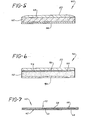
- FIGs. 5 and 6 illustrate, in cross-section, plastic-capped adhesive articles produced by alternative embodiments of the present invention.
- Article 40 has a layer of pressure sensitive adhesive 42 having a first upper surface 43 and a second lower surface.
- the lower surface of adhesive 42 is adhered to a release liner 44 or other releasable support surface.
- the adhesive 42 may then optionally be treated to render the upper surface 43 of the adhesive substantially tack free and suitable for printing indicia 48 directly thereon as discussed above.
- the lower surface of adhesive 42 remains tacky so that the finished article may be adhered to an intended surface.
- any suitable indicia 48 may be printed directly thereon.
- Adhesive layer 42 may itself be colored by the addition of suitable pigments or dyes to the composition. If layer 42 is already colored, the need for overprinting a colored background and/or treating the upper surface 43 of adhesive 42 to render it substantially tack free may be eliminated. Likewise, if layer 42 is clear, areas of the upper surface of the adhesive may be left undecorated by indicia 48 so that when the article is applied to a substrate, the color or brightness of the substrate shows through in those areas.
- a curable liquid plastic resin is applied onto the structure.
- the liquid plastic resin is cast onto the structure and flows to the edges of the structure forming a positive-shaped meniscus. This meniscus contributes to the lens effect of plastic cap 50 which is formed when the resin is cured.
- a relatively flat cap such as is illustrated in Fig. 6, may be applied by flow coating, spraying, or extruding a liquid resin onto the upper surface of the structure.
- flow coating, spraying, or extruding a liquid resin onto the upper surface of the structure.
- individual articles may then be die cut, stamped out, or otherwise separated from the larger sheet.
- the individual articles may be kiss-cut (i.e.. cut through to release liner 44) and left on the larger sheet or roll. In this manner, they may be shipped to ultimate users who may then readily peel the individual articles from release liner 44 for adherence to intended substrates.
- article 60 has a layer of pressure sensitive adhesive 62 having an upper and a lower surface.
- the lower surface of adhesive 62 is adhered to a release liner 64.
- the upper surface 63 of adhesive 62 has been treated, as explained in further detail above, to render it substantially tack free.
- a non-tacky surface 66 covers the upper surface of adhesive 62.
- any suitable indicia 68 may be printed directly thereon.
- a clear or colored plastic sheet 70 is laminated to the assembly. Any of a number of different plastics may be utilized depending upon the effect desired, and the intended environment for the article.
- the layer may be a polyester or polyolefin plastic.
- the lower surface of layer 70 may have an adhesive thereon to bond to the assembly.
- a plurality of individual decorated articles may be supported on a single larger sheet or web of release liner 64.
- Liquid plastic resin may then be cast, coated, sprayed, extruded or otherwise applied over the entire sheet or web. Such a procedure produces a relatively flat plastic cap over the entire sheet.
- individual articles may be die cut, stamped out, or otherwise separated from the larger sheet.
- the individual articles may be kiss-cut (i.e., cut through to release liner 64) and left on the larger sheet. In this manner, they may be shipped and sold to ultimate users who may then readily peel individual articles from the release liner 64 for adherance to intended substrates.
- a unique substrateless (i.e., meaning that there is no self-supporting paper, cardboard, or plastic stock as such) article is produced which is useful as trim strips on automobile bodies, inserts for bumpers and bumper guards, or as decoration or reflectors on tailgates, walls, doors, protective headgear, and the like.
Landscapes
- Chemical & Material Sciences (AREA)
- Dispersion Chemistry (AREA)
- Laminated Bodies (AREA)
- Adhesive Tapes (AREA)
Applications Claiming Priority (4)
| Application Number | Priority Date | Filing Date | Title |
|---|---|---|---|
| US06/820,106 US4737225A (en) | 1985-06-12 | 1986-01-21 | Method of making a substrateless decorative article |
| US820106 | 1986-01-21 | ||
| US06/820,646 US4643790A (en) | 1985-06-12 | 1986-01-21 | Plastic-capped adhesive article and method for making same |
| US820646 | 1986-01-21 |
Publications (3)
| Publication Number | Publication Date |
|---|---|
| EP0230713A2 true EP0230713A2 (fr) | 1987-08-05 |
| EP0230713A3 EP0230713A3 (en) | 1988-07-27 |
| EP0230713B1 EP0230713B1 (fr) | 1992-01-02 |
Family
ID=27124425
Family Applications (1)
| Application Number | Title | Priority Date | Filing Date |
|---|---|---|---|
| EP19860307029 Expired EP0230713B1 (fr) | 1986-01-21 | 1986-09-11 | Baguette décorative sans substrat et son mode de fabrication |
Country Status (2)
| Country | Link |
|---|---|
| EP (1) | EP0230713B1 (fr) |
| DE (1) | DE3683279D1 (fr) |
Cited By (1)
| Publication number | Priority date | Publication date | Assignee | Title |
|---|---|---|---|---|
| FR2660239A1 (fr) * | 1990-03-29 | 1991-10-04 | Profil | Procede et dispositif de fabrication de pieces moulees adhesives et pieces obtenues selon ce procede. |
Family Cites Families (5)
| Publication number | Priority date | Publication date | Assignee | Title |
|---|---|---|---|---|
| US4330352A (en) * | 1977-08-19 | 1982-05-18 | Stauffer Chemical Company | Method of forming a metallized decorative film laminate |
| US4446179A (en) * | 1982-05-21 | 1984-05-01 | The D. L. Auld Company | Trim strip for automobile bodies |
| JPS60140740U (ja) * | 1984-02-29 | 1985-09-18 | 豊田合成株式会社 | サイドモ−ル |
| US4560596A (en) * | 1984-05-21 | 1985-12-24 | The D. L. Auld Company | Decorative trim strips and process for making the same |
| US4612075A (en) * | 1985-06-12 | 1986-09-16 | The D. L. Auld Company | Substrateless trim strip and method of making |
-
1986
- 1986-09-11 EP EP19860307029 patent/EP0230713B1/fr not_active Expired
- 1986-09-11 DE DE8686307029T patent/DE3683279D1/de not_active Expired - Fee Related
Cited By (1)
| Publication number | Priority date | Publication date | Assignee | Title |
|---|---|---|---|---|
| FR2660239A1 (fr) * | 1990-03-29 | 1991-10-04 | Profil | Procede et dispositif de fabrication de pieces moulees adhesives et pieces obtenues selon ce procede. |
Also Published As
| Publication number | Publication date |
|---|---|
| EP0230713B1 (fr) | 1992-01-02 |
| DE3683279D1 (de) | 1992-02-13 |
| EP0230713A3 (en) | 1988-07-27 |
Similar Documents
| Publication | Publication Date | Title |
|---|---|---|
| US4645556A (en) | Substrateless decorative embedded article and method of making | |
| US4446179A (en) | Trim strip for automobile bodies | |
| US4737225A (en) | Method of making a substrateless decorative article | |
| US4716052A (en) | Method of making pressure sensitive adhesive tag or label stock | |
| US4566929A (en) | Process for making a trim strip for automobile bodies | |
| US4556588A (en) | Decorative emblem useful in customizing an automobile and other surfaces | |
| EP0381856A2 (fr) | Baguette décorative à profondeur de vision augmentée | |
| US4612075A (en) | Substrateless trim strip and method of making | |
| JPH04232990A (ja) | 看板 | |
| US5480688A (en) | Shaped flexible decorative articles and method for making same | |
| EP0102205B1 (fr) | Appareil pour fabriquer des feuilles façonnées ayant une calotte en matière plastique coulée | |
| US4560596A (en) | Decorative trim strips and process for making the same | |
| USRE32819E (en) | Trim strip for automobile bodies | |
| EP0320225B1 (fr) | Objet décoratif et son procédé de fabrication | |
| US4781952A (en) | Decorative article and process for making | |
| EP0230713B1 (fr) | Baguette décorative sans substrat et son mode de fabrication | |
| KR940011822B1 (ko) | 보호용 투명피복층을 가지는 건식전사제품 | |
| EP0234091B1 (fr) | Emblème décoratif sans substrat et son mode de fabrication | |
| EP0085732B1 (fr) | Imitation de peintures sur verre et de vitraux sertis de plomb | |
| EP0693993B1 (fr) | Dispositif d'alignement de graphiques et procedes de fabrication de ce dispositif | |
| JPS6361176B2 (fr) | ||
| JPS61290051A (ja) | 基体を有しないトリムストリツプおよびその製造方法 | |
| JPS61286120A (ja) | 基体を有しない装飾エンブレムの製造方法 | |
| JPS59161438A (ja) | 表面加飾を施した合成樹脂製品およびその表面加飾方法 | |
| JPH0889882A (ja) | 保護クリヤー層を成層する方法 |
Legal Events
| Date | Code | Title | Description |
|---|---|---|---|
| PUAI | Public reference made under article 153(3) epc to a published international application that has entered the european phase |
Free format text: ORIGINAL CODE: 0009012 |
|
| AK | Designated contracting states |
Kind code of ref document: A2 Designated state(s): DE FR GB IT |
|
| PUAL | Search report despatched |
Free format text: ORIGINAL CODE: 0009013 |
|
| AK | Designated contracting states |
Kind code of ref document: A3 Designated state(s): DE FR GB IT |
|
| 17P | Request for examination filed |
Effective date: 19890119 |
|
| 17Q | First examination report despatched |
Effective date: 19901004 |
|
| ITTA | It: last paid annual fee | ||
| GRAA | (expected) grant |
Free format text: ORIGINAL CODE: 0009210 |
|
| ITF | It: translation for a ep patent filed | ||
| AK | Designated contracting states |
Kind code of ref document: B1 Designated state(s): DE FR GB IT |
|
| REF | Corresponds to: |
Ref document number: 3683279 Country of ref document: DE Date of ref document: 19920213 |
|
| ET | Fr: translation filed | ||
| PLBE | No opposition filed within time limit |
Free format text: ORIGINAL CODE: 0009261 |
|
| STAA | Information on the status of an ep patent application or granted ep patent |
Free format text: STATUS: NO OPPOSITION FILED WITHIN TIME LIMIT |
|
| 26N | No opposition filed | ||
| PGFP | Annual fee paid to national office [announced via postgrant information from national office to epo] |
Ref country code: FR Payment date: 19950811 Year of fee payment: 10 |
|
| PGFP | Annual fee paid to national office [announced via postgrant information from national office to epo] |
Ref country code: DE Payment date: 19950818 Year of fee payment: 10 |
|
| PGFP | Annual fee paid to national office [announced via postgrant information from national office to epo] |
Ref country code: GB Payment date: 19950825 Year of fee payment: 10 |
|
| PG25 | Lapsed in a contracting state [announced via postgrant information from national office to epo] |
Ref country code: GB Effective date: 19960911 |
|
| PG25 | Lapsed in a contracting state [announced via postgrant information from national office to epo] |
Ref country code: FR Effective date: 19960930 |
|
| GBPC | Gb: european patent ceased through non-payment of renewal fee |
Effective date: 19960911 |
|
| PG25 | Lapsed in a contracting state [announced via postgrant information from national office to epo] |
Ref country code: DE Effective date: 19970603 |
|
| REG | Reference to a national code |
Ref country code: FR Ref legal event code: ST |
|
| REG | Reference to a national code |
Ref country code: FR Ref legal event code: ST |
|
| PG25 | Lapsed in a contracting state [announced via postgrant information from national office to epo] |
Ref country code: IT Free format text: LAPSE BECAUSE OF NON-PAYMENT OF DUE FEES;WARNING: LAPSES OF ITALIAN PATENTS WITH EFFECTIVE DATE BEFORE 2007 MAY HAVE OCCURRED AT ANY TIME BEFORE 2007. THE CORRECT EFFECTIVE DATE MAY BE DIFFERENT FROM THE ONE RECORDED. Effective date: 20050911 |