EP0231027A2 - Vorrichtung zur Lichttransmissionsprüfung - Google Patents
Vorrichtung zur Lichttransmissionsprüfung Download PDFInfo
- Publication number
- EP0231027A2 EP0231027A2 EP87101210A EP87101210A EP0231027A2 EP 0231027 A2 EP0231027 A2 EP 0231027A2 EP 87101210 A EP87101210 A EP 87101210A EP 87101210 A EP87101210 A EP 87101210A EP 0231027 A2 EP0231027 A2 EP 0231027A2
- Authority
- EP
- European Patent Office
- Prior art keywords
- coherent light
- transmissivity
- signal
- inspection
- specific pattern
- Prior art date
- Legal status (The legal status is an assumption and is not a legal conclusion. Google has not performed a legal analysis and makes no representation as to the accuracy of the status listed.)
- Granted
Links
Images


Classifications
-
- G—PHYSICS
- G01—MEASURING; TESTING
- G01N—INVESTIGATING OR ANALYSING MATERIALS BY DETERMINING THEIR CHEMICAL OR PHYSICAL PROPERTIES
- G01N21/00—Investigating or analysing materials by the use of optical means, i.e. using sub-millimetre waves, infrared, visible or ultraviolet light
- G01N21/17—Systems in which incident light is modified in accordance with the properties of the material investigated
- G01N21/47—Scattering, i.e. diffuse reflection
- G01N21/4738—Diffuse reflection, e.g. also for testing fluids, fibrous materials
-
- B—PERFORMING OPERATIONS; TRANSPORTING
- B07—SEPARATING SOLIDS FROM SOLIDS; SORTING
- B07C—POSTAL SORTING; SORTING INDIVIDUAL ARTICLES, OR BULK MATERIAL FIT TO BE SORTED PIECE-MEAL, e.g. BY PICKING
- B07C5/00—Sorting according to a characteristic or feature of the articles or material being sorted, e.g. by control effected by devices which detect or measure such characteristic or feature; Sorting by manually actuated devices, e.g. switches
- B07C5/34—Sorting according to other particular properties
- B07C5/342—Sorting according to other particular properties according to optical properties, e.g. colour
-
- B—PERFORMING OPERATIONS; TRANSPORTING
- B07—SEPARATING SOLIDS FROM SOLIDS; SORTING
- B07C—POSTAL SORTING; SORTING INDIVIDUAL ARTICLES, OR BULK MATERIAL FIT TO BE SORTED PIECE-MEAL, e.g. BY PICKING
- B07C5/00—Sorting according to a characteristic or feature of the articles or material being sorted, e.g. by control effected by devices which detect or measure such characteristic or feature; Sorting by manually actuated devices, e.g. switches
- B07C5/36—Sorting apparatus characterised by the means used for distribution
- B07C5/363—Sorting apparatus characterised by the means used for distribution by means of air
- B07C5/365—Sorting apparatus characterised by the means used for distribution by means of air using a single separation means
Definitions
- the present invention relates to a transmissivity inspection apparatus which is applied to a glass molding technique and is used for detecting and removing nontransparent substances for coherent light, such as stones, ceramics, and the like, mixed in transparent substances for coherent light, such as glass fragments.
- glass molding includes a process of charging transparent glass fragments as raw materials into a furnace to melt them.
- nontranslucent or nontransparent foreign matter other than the glass fragments such as stones, ceramics, and the like are mixed in the glass fragments, defective products are molded, and the furnace itself could be damaged. Therefore, it is important to remove foreign matter from recovered glass fragments during the glass molding processes.
- coherent light is radiated onto an object to be inspected, irregularly reflected light components produced in the object are detected, and a transmissivity of the object with respect to the light is inspected based on the irregularly reflected light components detected.
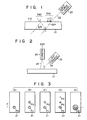
- Figs. l to 6A and 6B explain the principle of the operation of this invention, in which:
- laser beam 23 is radiated from light (laser) source 22 onto a substance (object 2l to be inspected), such as glass, which is transparent for coherent light.
- a substance such as glass
- Laser beam 23 is scattered at surface 2la of the translucent substance due to its reflection, absorption, transmission, etc.
- Transmission beam 23* arrives at interface 2lb while being absorbed during transmission to decrease in amount of light, and is also scattered at interface 2lb due to its reflection, absorption, transmission, and the like. The same phenomenon is repeated at surface 2la or interface 2lb.
- Emission directions of reflected beams 24a and 24b depend on the surface condition of the translucent substance (2l). More specifically, if the surface is almost a smooth plane, the amount of irregular reflection components (indicated by solid arrows in Fig. l) decreases while the amount of regular reflection components (indicated by broken arrows in Fig. l) increases.
- object 2l is a nontranslucent substance, such as stones, ceramics, and the like, an interference phenomenon including only reflection and absorption occurs on the surface of object 2l, and there are no transmission beams.
- pieces of glass having different transmissivities and nontranslucent substances are selected, and are irradiated with laser beams 23 so as to detect irregular reflection components by camera 25, as shown in Fig. 2.
- Figs. 3A-3E exemplifies several reflection patterns (slanted portions) scanned by camera 25.
- Fig. 3A shows an irradiation pattern of light source 22 (irradiation position or beam spot position is indicated by P);
- Fig. 3B shows a reflection pattern of a piece of glass with low transmissivity;
- Fig. 3C shows a reflection pattern of a piece of glass with medium transmissivity;
- Fig. 3D shows a reflection pattern of a piece of glass with high transmissivity;
- Fig. 3E shows a reflection pattern of a nontranslucent substance.
- laser beam 23 is converted into scan beam 23S by scanning the direction of beam 23 in the widthwise direction of object 2l using rotary mirror 26, and scan beam 23S is radiated onto object 2l. Then, reflection pattern P25 (Figs. 6A and 6B), formed by the scanning of beam 23S, is detected by camera 25.
- object 2l When object 2l is glass having a transmissivity higher than a predetermined transmissivity, it causes a pattern with different widths because the intensity of scanned reflected beams 24S obtained at each of two end portions of object 2l is larger than that obtained at the intermediate portion thereof, as shown by the slanted portion 25l in Fig. 6A.
- object 2l When object 2l is a nontranslucent substance having a transmissivity lower than the predetermined transmissivity, it causes a pattern with a substantially constant width, as shown by the slanted portion 252 in Fig. 6B.
- detecting abrupt changes (X in Fig. 6A) in reflection pattern P25 or detecting a certain length (L in Fig. 6A) of the narrowed portion of reflection pattern P25 glass can be distinguished from a nontranslucent substance.
- reflection pattern P25 (Fig. 6A) has portion X indicating abrupt change, or when pattern P25 includes narrowed portion 25l with length L, it can be discriminated as glass.
- reflection pattern P25 (Fig. 6B) does not have a portion indicating abrupt change, it can be discriminated as a nontranslucent substance.
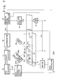
- Fig. 7 is a block diagram showing a system configuration of a first embodiment of the present invention.
- reference numeral l denotes a conveyor belt line (to be referred to simply as a conveyor line hereinafter).
- Conveyor line l is pivoted upon rotation of roller 3, and roller 3 is driven by motor 2, so that objects 2l to be inspected are fed, one by one, to the next process (in the direction indicated by arrow v).
- objects 2l, mixed with foreign matter (stones, ceramics, etc.) 2lF, are glass fragments 2lG used in a glass molding process.
- Light source 22 emits coherent light, for example, laser beam 23.
- Laser beam 23 is sequentially radiated onto point P, as shown in Fig. 7, to form a beam spot on object 2l.
- Reflected light detector 25R formed of a plurality of photoelectric converters, detects from reflected beam 24 the irregular reflection components of laser beam 23.
- detector 25R detects the patterns as shown in Figs. 4A and 4B. More specifically, the photoelectric converters of detector 25R are arranged at given positions at which reflected beam 24 with reflection angle ⁇ 2, which is different from laser beam incident angle ⁇ l, can be detected.
- Data acquisition system (DAS) 9 acquires electrical signals E25 from the respective photoelectric converters of detector 25R, and acquired signals E9 are subjected to predetermined preprocessing, such as filtering, in preprocessor l0. Thereafter, preprocessed signal El0 from preprocessor l0 is converted to binary signal Ell via binary converter ll. This binary signal Ell represents a signal obtained by level-slicing signal E25 shown in Figs. 4A and 4B.
- Discriminator l2 discriminates, based on binary signal Ell delivered from converter ll, whether object 2l is glass fragment 2lG or foreign matter 2lF. If it is discriminated that object 2l under inspection is foreign matter 2lF, foreign matter removal instruction (inspection signal) El2 is supplied to removing mechanism controller l3.
- a material, having a transmissivity lower than a predetermined transmissivity, is defined as foreign matter 2lF.
- Removing mechanism controller l3 controls driving operations of suction pump l4 and air jet l5 arranged opposite thereto. Upon operation of suction pump l4 and air jet l5, only foreign matters 2lF contained in many objects 2l are removed from conveyor line l.
- Main controller l6 controls start timing and rotating speed of motor 2, and also controls data acquisition timing of DAS 9 as well as activation timing of removing mechanism controller l3.
- the activation timing of controller l3 is determined by removal start instruction El6l generated from controller l6.
- the generation timing of instruction El6l depends on feeding speed v of conveyor line l, distance LX between beam spot position P and foreign matter removing position Q, and the timing of generation of instruction El2.
- Motor (pulse motor) 2 is driven under the control of main controller l6, and conveyor line l runs so that objects 2l are conveyed, one by one, along line l.
- laser beam 23 is radiated from light source 22 onto object 2l to form a laser spot thereon.
- irregular reflection components of beam 24, reflected by the surface of object 2l are detected by reflected light detector 25R.
- Detector 25R converts the reflection components of beam 24 to electrical signal E25, and signal E25 is then acquired by DAS 9.
- Electrical signal E25 is subjected to predetermined preprocessing in preprocessor l0, and is then converted into binary signal Ell via binary converter ll, using a threshold level being higher than the signal level of E25 obtained for glass fragment 2lG but lower than that obtained for foreign matter 2lF.
- Removing mechanism controller l3 is controlled by main controller l6 in accordance with the relationship between distance LX between the beam spot position P of laser beam 23 and position Q of pump l4 and air jet l5, and with the feeding speed of conveyor line l. If controller l3 receives removal instruction El2 from discriminator l2, it activates pump l4 and air jet l5 when removal start instruction El6l is supplied from main controller l6. Then, at position Q, foreign matter 2lF is blown by air jet l5, and is drawn by suction pump l4. In this manner, foreign matter 2lF is removed from conveyor line l.
- laser beam 23 is radiated onto object 2l, which is conveyed along conveyor line l, to form beam spots thereon, and irregular reflection components of reflected beams 24 upon laser beam radiation are detected and converted to electrical signal E25. It is then discriminated by discriminator l2, based on the signal levels of electrical signal E25, whether object 2l under inspection is glass fragment 2lG or foreign matter 2lF. If object 2l is discriminated to be foreign matter 2lF, foreign matter 2lF is removed from line l by the action of pump l4 and air jet l5.
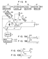
- Fig. 8 is a block diagram showing the main part of a second embodiment of the present invention.
- laser beam 23 emitted from light source 22 is converted into linearly scanned beam 23S by rotary mirror 26, and scanned beam 23S is radiated onto object 2l along the widthwise direction of conveyor line l. Namely, beam 23S is scanned along line P.
- the reflection pattern of each of objects 2l is detected by reflected light detector 25R which is formed of a line sensor.
- the reflection pattern detected by detector 25R, becomes a specific pattern whose two ends indicate irregular reflection and which has a narrow intermediate portion, as shown in Fig. 6A.
- the entire detected pattern indicates significant irregular reflection, as shown in Fig. 6B.
- the reflection pattern is subjected to predetermined preprocessing by preprocessor l0.
- Preprocessed output El0 from preprocessor l0 is differentiated by differentiator 33 to detect the rate of change of the signal edge of output El0.
- the waveform of differentiated output signal E33 from differentiator 33 is shown in Fig. 9A when object 2l is glass fragment 2lG, and is shown in Fig. 9B when it is foreign matter 2lF.
- Signal E33 is converted into pulse signal E34, via signal detector 34, using predetermined positive and negative threshold levels.
- differentiated signal E33 of Fig. 9A is converted into pulse signal E34 of Fig. l0A
- differentiated signal E33 of Fig. 9B is converted into pulse signal E34 of Fig. l0B.
- Pulse signal E34 shown in Fig. l0A is detected in the case of glass fragment 2lG
- pulse signal E34 shown in Fig. l0B is detected in the case of the foreign matter 2lF.
- pulse signal E34 includes portions PSl and PS2 as shown in Fig. l0A
- foreign matter discriminator l2* discriminates glass fragment 2lG having a transmissivity higher than a predetermined transmissivity. If pulse signal E34 does not include portions PSl and PS2 as shown in Fig. l0B, foreign matter discriminator l2* discriminates foreign matter 2lF having a transmissivity lower than the predetermined transmissivity, and generates foreign matter removal instruction El2*. When a removing mechanism similar to that in the first embodiment is used, foreign matter 2lF can be removed in accordance with the generation of removal instruction El2*.
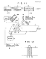
- Fig. ll is a block diagram showing the main part of a third embodiment of the present invention.
- the case has been exemplified wherein objects 2l are conveyed along conveyor line l one by one.
- a plurality of objects 2l are irregularly conveyed, and laser beam 23S, obtained via rotary mirror 26 from light source 22, is scanned in the widthwise direction of conveyor line l.
- reflected beams (irregular reflection components) 24S from objects 2l are detected for each scanning operation by reflected light detector 25R on which a plurality of photoelectric conversion elements (not shown) are aligned.
- Detector 25R receives, at its photoelectric conversion elements, reflected beams 24S from positions Nl and N2 of conveyor line l, which are separated by distance D (see Fig. l2).
- Laser beam irradiation position M on conveyor line l is located at the center of distance D, as shown in Fig. l2.
- Distance D is larger than the width of the narrowed portion of reflection pattern 25l (Fig. 6A) of glass fragment 2lG, but is smaller than the width of reflection pattern 252 (Fig. 6B) of foreign matter 2lF.
- Discriminator l2 performs foreign matter discrimination based on binary signals Ell. Discriminator l2 also detects specific conveyance position PX of foreign matter 2lF in accordance with scan position signal E42 detected by scan position detector 42, which indicates the position of scanning of beam 23S with respect to irradiation locus IL along the widthwise direction of on conveyor line l.
- discriminator l2 may include a rotary encoder (not shown), coupled to rotary mirror 26, for generating pulses indicating the scanning angle of beam 23S, and a microcomputer responsive to the pulses from the rotary encoder and binary signals Ell from binary converter ll.
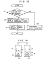
- discriminator l2 operates in accordance with the flow chart shown in Fig. l3.
- discriminator l2 checks whether or not the number of binary data "l" continues for a predetermined length (step STl). If data "l" does not continue for the predetermined length, it is discriminated that no foreign matter 2lF is present at the scan position of laser beam 23S, and that all objects 2l are glass fragments 2lG (step ST2).
- step ST3 a distance, from the laser beam scan start position (e.g., side edge portion la of conveyor line l) to the position from which the first one of the continuous data "l", is detected from laser beam scan position signal E42 (step ST3). Then, foreign matter removal instruction El2**, containing the widthwise distance information of step ST3, is sent to removing mechanism controller l3 of, e.g., Fig. 7 (step ST4).
- Foreign matter 2lF at specific conveyance position PX on line l can thus be removed upon operation of, for example, parallel-arranged plural sets of a pump (l4) and air jet (l5), one of which sets (l4+l5) is selectively activated in accordance with the widthwise distance information contained in removal instruction El2**.
- a pump (l4) and air jet (l5) one of which sets (l4+l5) is selectively activated in accordance with the widthwise distance information contained in removal instruction El2**.
- one parallel-slidable set of pump (l4) and air jet (l5) which can be moved along the widthwise direction of line l in accordance with the widthwise distance information of El2**, can be used.
- the circuit configuration of this embodiment may be the same as that shown in Fig. 7.
- sizes of reflection patterns (Pl, Pl0) obtained by glass fragment 2lG and foreign matter 2lF with respect to laser beam spot P0, are different from each other.
- the fourth embodiment utilizes this difference of the reflection patterns.
- the fourth embodiment is provided with a photoelectric conversion element (not shown) responsive to reflection sensing area PY near irradiation position P, which is capable of detecting only reflection pattern Pl0 of foreign matter 2lF whose transmissivity is lower than a predetermined transmissivity, without detecting reflection pattern Pl of glass fragment 2lG.
- a photoelectric conversion element is arranged in place of reflected light detector 25R shown in Fig. 7 etc. In this manner, glass fragment 2lG and foreign matter 2lF can be distinguished from each other based on the output signal from the photoelectric conversion element.
- a two-dimensional area sensor (not shown) for detecting reflection sensing area PZ in Figs. l4A and l4B can be used in place of, or together with, the photoelectric conversion element for detecting reflection sensing area PZ.
- This two-dimensional area sensor is arranged such that it does not respond to foreign matter pattern Pl0 as shown in Fig. 3E, but it senses glass fragment patterns P2 and/or P3 as shown in Figs. 3B-3D.
- Fig. l5 is a block diagram showing the main part of a fifth embodiment of the present invention.
- the apparatus of this embodiment has the same functions as that of the first embodiment in Fig. 7. However, in this embodiment, inspection is performed not for objects 2l being conveyed along conveyor line l, but for objects 2l falling from first conveyor line lA to second conveyor line lB, by irradiating them with laser beam 23.
- reflected light detector 25R is coupled to circuit elements 9-l2 of Fig. 7, so that the irregular reflection components of reflected beam 24 are discrimination, and glass fragments 2lG and foreign matter 2lF are distinguished from each other.
- the detected foreign matter (2lF) is blown by air jet l5, so that it does not fall on second conveyor line lB.
- foreign matter 2lF can be removed from a number of objects 2l, and only glass fragments 2lG are collected on second conveyor line lB.
- a reflection pattern detection system (22+25R) is arranged at the left side of Fig. l5. However, it can be arranged at the right side thereof.
- this detection system (22+25R) is arranged as now presently illustrated in Fig. l5
- distances Ll and L2 between the detection system (22+25R) and object 2l under inspection can be made substantially constant.
- distances Ll and L2 vary, depending on the thicknesses of object 2l, and the inspection apparatus could be operated erroneously.
- the present invention is not limited to the first to fifth embodiments.
- the apparatus is used for distinguishing glass fragments 2lG (translucent substances) from foreign matters 2lF (nontranslucent substances, such as stones, ceramics, etc.).
- the present invention can be applied to an inspection apparatus for discriminating a material having a unique transmissivity upon radiation of coherent light, for example, laser beam 23.
- the distance between patterns Pl and P2 or between P2 and P3 in Fig. 3D changes in accordance with the thickness of object 2l, such as a glass plate. Accordingly, the flatness of plate-like object 2l can be inspected by measuring the distance between patterns Pl and P2 or between P2 and P3.
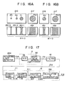
- Fig. l6A illustrates patterns obtained for translucent material (glass) 2lG and nontranslucent material (foreign matter such as stone) 2lF where laser beam incident angle ⁇ l shown in Fig. 7 is not zero.
- Fig. l6A teaches that all areas Pl-P3 of translucent material 2lG are smaller than area Pl0 of nontranslucent material 2lF.
- the distance between Pl and P2 (or P2 and P3) becomes long as the thickness of translucent material 2lG becomes large.
- the area of P2 (or P3) becomes small as the thickness of translucent material 2lG becomes large.
- patterns 25l-l to 25l-3 obtained by the laser beam scanning, becomes narrow as the thickness of translucent material 2lG becomes large, and the width of each of these patterns (25l-l to 25l-3) is narrower than the width of pattern 252 obtained for nontranslucent material 2lF.
- Fig. l6B illustrates patterns obtained for translucent and nontranslucent materials where laser beam incident angle ⁇ l shown in Fig. 7 is zero.
- Fig. l6B teaches that area P0 of translucent material 2lG is smaller than area P00 of nontranslucent material 2lF, and that the width of pattern 25l, obtained by the laser beam scanning, is narrower than that of pattern 252 obtained for nontranslucent material 2lF.
- Fig. l7 shows details of circuit elements 9-l2 in Fig. 7.
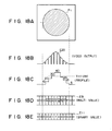
- Figs. l8A-l8E exemplify the contents of signals obtained from the circuit elements in Fig. l7.
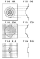
- Fig. l9A shows an example of the reflected light pattern (Pl-P3, Pl0, etc.) having three different intensities.
- Fig. l9B shows a profile of the pattern shown in Fig. l9A, which is obtained from profile detector l2A in Fig. l7.
- Fig. 20A shows an example of the memory arrangement of binary-converted signal Ell obtained for a low intensity pattern image.
- Fig. 20B shows a profile of the low intensity pattern image corresponding to Fig. 20A.
- Fig. 2lA shows an example of the memory arrangement of binary-converted signal Ell obtained for a high intensity pattern image.
- Fig. 2lB shows a profile of the high intensity pattern image corresponding to Fig. 2lA.
- Analog signal E25 (Fig. l8B), containing pattern information (Pl) as shown in Fig. l8A, is supplied from reflected light detector 25R to A/D converter 9A.
- A/D converter 9A provides multi-value digital signal E9A which represents the intensity of signal E25.
- Such digital signal E9A is stored in multi value memory 9B.
- Digital output E9 (Fig. l8D) from memory 9B, corresponding to signal E9A, is filtered by filter l0 so as to eliminate noise from output E9. Then, filtered signal El0 is converted, via binary converter llA, into binary signal EllA. Binary signal EllA is stored in binary memory llB.
- Binary output Ell (Fig. l8E) from memory llB is supplied to profile detector l2A.
- Detector l2A detects, based on data "l" of output Ell, the profile (Figs. l8C, l9B-2lB) of the detected image pattern.
- the area of the profile is detected in calculator/discriminator l2B, by calculating the total number of the data "l” encircled within the profile of output Ell.
- calculator/discriminator l2B discriminates that the object (2l), providing signal E25, is foreign matter 2lF, and generates foreign matter removal instruction El2.
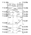
- Figs. 22A-22I are timing charts explaining how a translucent pattern (25l) is discriminated by discriminator l2* in Fig. 8.
- Figs. 23A-23I are timing charts explaining how a nontranslucent pattern (252) is discriminated by discriminator l2* in Fig. 8.
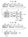
- Fig. 24 shows an example of circuit elements 34 and l2* in Fig. 8, which is responsive to a discrimination value (DREF) shown in Figs. 22F and 23F.
- DREF discrimination value
- Fig. 24 responds to sensing area SAl or SA3 shown in Figs. 22A and 23A.
- Differentiated output signal E33 (Figs. 22C and 23C) from differentiator 33 is supplied to positive detector 34P and negative detector 34N.
- Positive detector 34P responds only to the positive component of signal E33 and outputs positive pulse E34P (Figs. 22D and 23D).
- Negative detector 34N responds only to the negative component of signal E33 and outputs negative pulse E34N (Figs. 22E and 23E).
- Pulse E34P is supplied to up-counter l2l, so that counter l2l starts up-counting of clock pulse CK.
- Pulse E34N is also supplied to counter l2l, so that counter l2l stops the counting of clock pulse CK, and it is then cleared.
- Count value Dl2l (Figs. 22F and 23F) of counter l2l is latched by a latch (not shown) contained in counter l2l, before it is cleared.
- Count value Dl2l is compared with predetermined reference value DREF at comparator l22.
- discriminator l2* discriminates that the object (2l) under inspection is, for example, glass, and no removal instruction l2* is generated (Fig. 22G). If Dl2l ⁇ DREF, discriminator l2* discriminates that the object (2l) under inspection is, for example, stone, and removal instruction l2* is generated (Fig. 23G).
- Fig. 25 shows an example of circuit elements 34 and l2* in Fig. 8, which is responsive to detection area SA2 shown in Figs. 22A and 23A and to discrimination threshold level VTHl shown in Figs. 22B and 23B.
- Differentiated output signal E33 (Figs. 22C and 23C) from differentiator 33 is supplied to positive detector 34P.
- Positive detector 34P responds only to the positive component of signal E33 having a signal level higher than VTHl.
- E33 ⁇ VTHl detector 34P provides no pulse.
- comparator l2* generates removal instruction El2* in response to E34P (Fig. 23G).
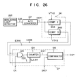
- Fig. 26 shows an example of circuit elements 34 and l2* in Fig. 8, which is responsive to detection area SA2 shown in Figs. 22A and 23A and to discrimination threshold levels VTH2 and VTH3 shown in Figs. 22B and 23B.
- Analog video signal E25 from reflected light detector 25R is analog-to-digital converted via A/D converter l0*.
- A/D converted digital signal El0* from converter l0* is supplied to digital comparators 34A and 34B.
- Comparator 34A compares the digital value of El0* with that of VTH2, and comparator 34B compares the digital value of El0* with that of VTH3.
- comparator 34B When an object (2l) exists in the inspection area, the relation El0* > VTH3 is always obtained, so that comparator 34B always generates pulse E34B with logic "l" level (Figs. 22H and 23H).
- comparator 34A When the object is translucent material 2lG, comparator 34A generates pulse E34A with logic "l” level, only if El0* > VTH2 (Figs. 22B and 22I).
- comparator 34A when the object is nontranslucent material 2lF, comparator 34A generates pulse E34A with logic "l” level, since El0* > VTH2 (Figs. 23B and 23I).
- Pulses 34A and 34B are input to AND gate l20.
- AND gate l20 also receives clock pulse CK.
- pulse CK passes AND gate l20 and is supplied to counter l2l.
- Counter l2l counts pulse CK until it is cleared.
- Counter l2l is cleared by the falling edge of pulse E34A.
- a latch (not shown) of counter l2l latches count value Dl2l of CK. This count value indicates the pulse width of E34A, and indicates whether or not the object (2l) is translucent.
- Count value Dl2l is compared with predetermined reference value DREF at comparator l22.
- discriminator l2* discriminates that the object (2l) under inspection is translucent, and no removal instruction l2* is generated (Fig. 22G).
- discriminator l2* discriminates that the object (2l) under inspection is nontranslucent, and removal instruction l2* is generated (Fig. 23G).
- a transmissivity inspection apparatus can automatically and highly reliably detect a nontranslucent substance mixed with translucent substances.
Landscapes
- Physics & Mathematics (AREA)
- Health & Medical Sciences (AREA)
- Life Sciences & Earth Sciences (AREA)
- Chemical & Material Sciences (AREA)
- Analytical Chemistry (AREA)
- Biochemistry (AREA)
- General Health & Medical Sciences (AREA)
- General Physics & Mathematics (AREA)
- Immunology (AREA)
- Pathology (AREA)
- Investigating Materials By The Use Of Optical Means Adapted For Particular Applications (AREA)
- Sorting Of Articles (AREA)
- Re-Forming, After-Treatment, Cutting And Transporting Of Glass Products (AREA)
Applications Claiming Priority (2)
| Application Number | Priority Date | Filing Date | Title |
|---|---|---|---|
| JP61019615A JPH0690149B2 (ja) | 1986-01-31 | 1986-01-31 | 透光度検査装置 |
| JP19615/86 | 1986-01-31 |
Publications (3)
| Publication Number | Publication Date |
|---|---|
| EP0231027A2 true EP0231027A2 (de) | 1987-08-05 |
| EP0231027A3 EP0231027A3 (en) | 1989-09-06 |
| EP0231027B1 EP0231027B1 (de) | 1993-04-14 |
Family
ID=12004089
Family Applications (1)
| Application Number | Title | Priority Date | Filing Date |
|---|---|---|---|
| EP87101210A Expired - Lifetime EP0231027B1 (de) | 1986-01-31 | 1987-01-29 | Vorrichtung zur Lichttransmissionsprüfung |
Country Status (4)
| Country | Link |
|---|---|
| US (1) | US4730932A (de) |
| EP (1) | EP0231027B1 (de) |
| JP (1) | JPH0690149B2 (de) |
| DE (1) | DE3785370T2 (de) |
Cited By (9)
| Publication number | Priority date | Publication date | Assignee | Title |
|---|---|---|---|---|
| GB2195438A (en) * | 1986-09-26 | 1988-04-07 | Pilkington Brothers Plc | Detecting unwanted materials among cullet |
| WO1993007468A1 (en) * | 1991-10-01 | 1993-04-15 | Oseney Limited | Scattered/transmitted light information system |
| AU638268B2 (en) * | 1989-08-17 | 1993-06-24 | Toyo Glass Company Limited | Method of detecting opaque foreign article from among transparent bodies |
| US5305894A (en) * | 1992-05-29 | 1994-04-26 | Simco/Ramic Corporation | Center shot sorting system and method |
| EP0620051A1 (de) * | 1993-04-16 | 1994-10-19 | Materiel Pour L'arboriculture Fruitiere (M.A.F.) S.A. | Verfahren und Vorrichtung zur automatischen Sortierung von Produkten, hauptsächlich von Früchten oder Gemüsen |
| AU670347B2 (en) * | 1993-01-21 | 1996-07-11 | Albert Peter Hawkins | Sorting translucent objects |
| FR2731075A1 (fr) * | 1995-02-24 | 1996-08-30 | Materiel Arboriculture | Procede et dispositif d'analyse de la structure interne de produits, tels que par exemple des produits carnes, des tubercules ou des vegetaux |
| US6545240B2 (en) * | 1996-02-16 | 2003-04-08 | Huron Valley Steel Corporation | Metal scrap sorting system |
| US9785851B1 (en) | 2016-06-30 | 2017-10-10 | Huron Valley Steel Corporation | Scrap sorting system |
Families Citing this family (27)
| Publication number | Priority date | Publication date | Assignee | Title |
|---|---|---|---|---|
| GB2219394B (en) * | 1988-05-06 | 1992-09-16 | Gersan Ets | Sensing a narrow frequency band of radiation and examining objects or zones |
| US5110213A (en) * | 1989-12-21 | 1992-05-05 | R. J. Reynolds Tobacco Company | Method and apparatus for measuring concentration of a material in a sample |
| US5751443A (en) * | 1996-10-07 | 1998-05-12 | Xerox Corporation | Adaptive sensor and interface |
| US6603554B1 (en) * | 2000-12-22 | 2003-08-05 | Terabeam Corporation | Apparatus and method to measure light attenuation through a window |
| US6590223B1 (en) | 2001-07-03 | 2003-07-08 | Lexmark International, Inc. | Apparatus and method for media presence detection |
| JP4333165B2 (ja) * | 2003-03-04 | 2009-09-16 | トヨタ自動車株式会社 | 土壌状態判定方法 |
| US7391898B2 (en) * | 2003-10-10 | 2008-06-24 | Nova Packaging Systems, Inc. | Method and apparatus for programmable zoned array counter |
| US7403722B2 (en) * | 2005-02-22 | 2008-07-22 | Lexmark International, Inc. | Integrated media and media tray sensing in an image forming device |
| US20070248366A1 (en) * | 2006-04-19 | 2007-10-25 | Lexmark International, Inc. | Devices for moving a media sheet within an image forming apparatus |
| US20070246880A1 (en) * | 2006-04-19 | 2007-10-25 | Kenji Totsuka | Methods For Moving A Media Sheet Within An Image Forming Device |
| US20070248365A1 (en) * | 2006-04-19 | 2007-10-25 | Lexmark International, Inc. | Methods for moving a media sheet within an image forming device |
| USRE46672E1 (en) | 2006-07-13 | 2018-01-16 | Velodyne Lidar, Inc. | High definition LiDAR system |
| US7699305B2 (en) * | 2007-03-29 | 2010-04-20 | Lexmark International, Inc. | Smart pick control algorithm for an image forming device |
| JP4983753B2 (ja) * | 2008-09-08 | 2012-07-25 | トヨタ自動車株式会社 | 土壌状態判定方法 |
| JP4894833B2 (ja) * | 2008-09-08 | 2012-03-14 | トヨタ自動車株式会社 | 土壌状態判定方法 |
| NO336546B1 (no) | 2010-09-24 | 2015-09-21 | Tomra Sorting As | Apparat og fremgangsmåte for inspeksjon av materie |
| US20140261170A1 (en) * | 2013-03-15 | 2014-09-18 | Hiti Digital, Inc. | Methods for detecting an edge of a transparent material and detecting devices and systems for same |
| US10627490B2 (en) | 2016-01-31 | 2020-04-21 | Velodyne Lidar, Inc. | Multiple pulse, LIDAR based 3-D imaging |
| CN109154661A (zh) | 2016-03-19 | 2019-01-04 | 威力登激光雷达有限公司 | 用于基于lidar的3-d成像的集成照射和检测 |
| US10393877B2 (en) | 2016-06-01 | 2019-08-27 | Velodyne Lidar, Inc. | Multiple pixel scanning LIDAR |
| WO2018183843A1 (en) | 2017-03-31 | 2018-10-04 | Velodyne Lidar, Inc. | Integrated lidar illumination power control |
| CN110809704B (zh) | 2017-05-08 | 2022-11-01 | 威力登激光雷达美国有限公司 | Lidar数据获取与控制 |
| US11294041B2 (en) | 2017-12-08 | 2022-04-05 | Velodyne Lidar Usa, Inc. | Systems and methods for improving detection of a return signal in a light ranging and detection system |
| US10712434B2 (en) | 2018-09-18 | 2020-07-14 | Velodyne Lidar, Inc. | Multi-channel LIDAR illumination driver |
| US11082010B2 (en) | 2018-11-06 | 2021-08-03 | Velodyne Lidar Usa, Inc. | Systems and methods for TIA base current detection and compensation |
| US11885958B2 (en) | 2019-01-07 | 2024-01-30 | Velodyne Lidar Usa, Inc. | Systems and methods for a dual axis resonant scanning mirror |
| CN110216808B (zh) * | 2019-06-05 | 2021-08-31 | 芜湖宝晟源新材料科技有限公司 | 一种塑料颗粒再生成型模具装置 |
Family Cites Families (8)
| Publication number | Priority date | Publication date | Assignee | Title |
|---|---|---|---|---|
| GB1305192A (de) * | 1969-05-19 | 1973-01-31 | ||
| US3693025A (en) * | 1969-11-28 | 1972-09-19 | Brun Sensor Systems Inc | Apparatus and method for eliminating interference errors in dual-beam infrared reflection measurements on a diffusely reflecting surface by geometrical elimination of interference-producing specularly-reflected radiation components |
| US3680965A (en) * | 1970-12-10 | 1972-08-01 | Us Army | Beamspread measurement camera for recording laser beam intensity distribution |
| US3807870A (en) * | 1972-05-22 | 1974-04-30 | G Kalman | Apparatus for measuring the distance between surfaces of transparent material |
| JPS585817B2 (ja) * | 1977-08-23 | 1983-02-01 | 株式会社整電社 | 軌条車両の洗浄方法 |
| JPS5632582A (en) * | 1979-08-23 | 1981-04-02 | Chugoku Toryo Kk | Method for increasing intensity of light emission of fluorescent material |
| AU563981B2 (en) * | 1983-03-23 | 1987-07-30 | Sphere Investments Ltd. | Ore sorting |
| GB2195438A (en) * | 1986-09-26 | 1988-04-07 | Pilkington Brothers Plc | Detecting unwanted materials among cullet |
-
1986
- 1986-01-31 JP JP61019615A patent/JPH0690149B2/ja not_active Expired - Lifetime
-
1987
- 1987-01-29 EP EP87101210A patent/EP0231027B1/de not_active Expired - Lifetime
- 1987-01-29 DE DE8787101210T patent/DE3785370T2/de not_active Expired - Fee Related
- 1987-02-02 US US07/009,752 patent/US4730932A/en not_active Expired - Lifetime
Cited By (17)
| Publication number | Priority date | Publication date | Assignee | Title |
|---|---|---|---|---|
| US4781742A (en) * | 1986-09-26 | 1988-11-01 | Pilkington Plc | Method and apparatus for detecting unwanted materials among cullet |
| EP0261840A3 (de) * | 1986-09-26 | 1989-10-18 | Pilkington Plc | Nachweis von ungewünschtem Material im Glassbruch |
| AU601486B2 (en) * | 1986-09-26 | 1990-09-13 | Pilkington Plc | Detecting unwanted materials among cullet |
| GB2195438A (en) * | 1986-09-26 | 1988-04-07 | Pilkington Brothers Plc | Detecting unwanted materials among cullet |
| AU638268B2 (en) * | 1989-08-17 | 1993-06-24 | Toyo Glass Company Limited | Method of detecting opaque foreign article from among transparent bodies |
| US5675419A (en) * | 1991-10-01 | 1997-10-07 | Van Den Bergh; Herman | Scattered/transmitted light information system |
| US5471311A (en) * | 1991-10-01 | 1995-11-28 | Van Den Bergh; Herman | Information system for monitoring products in sorting apparatus |
| WO1993007468A1 (en) * | 1991-10-01 | 1993-04-15 | Oseney Limited | Scattered/transmitted light information system |
| US5305894A (en) * | 1992-05-29 | 1994-04-26 | Simco/Ramic Corporation | Center shot sorting system and method |
| AU670347B2 (en) * | 1993-01-21 | 1996-07-11 | Albert Peter Hawkins | Sorting translucent objects |
| EP0620051A1 (de) * | 1993-04-16 | 1994-10-19 | Materiel Pour L'arboriculture Fruitiere (M.A.F.) S.A. | Verfahren und Vorrichtung zur automatischen Sortierung von Produkten, hauptsächlich von Früchten oder Gemüsen |
| FR2703932A1 (fr) * | 1993-04-16 | 1994-10-21 | Materiel Arboriculture | Procédé et dispositif de tri automatique de produits, notamment de fruits et légumes. |
| US5729473A (en) * | 1993-04-16 | 1998-03-17 | Materiel Pour L'arboriculture Fruitiere | Method and device for generating colorimetric data for use in the automatic sorting of products, notably fruits or vegetables |
| FR2731075A1 (fr) * | 1995-02-24 | 1996-08-30 | Materiel Arboriculture | Procede et dispositif d'analyse de la structure interne de produits, tels que par exemple des produits carnes, des tubercules ou des vegetaux |
| US6545240B2 (en) * | 1996-02-16 | 2003-04-08 | Huron Valley Steel Corporation | Metal scrap sorting system |
| US6795179B2 (en) | 1996-02-16 | 2004-09-21 | Huron Valley Steel Corporation | Metal scrap sorting system |
| US9785851B1 (en) | 2016-06-30 | 2017-10-10 | Huron Valley Steel Corporation | Scrap sorting system |
Also Published As
| Publication number | Publication date |
|---|---|
| US4730932A (en) | 1988-03-15 |
| JPH0690149B2 (ja) | 1994-11-14 |
| EP0231027B1 (de) | 1993-04-14 |
| DE3785370T2 (de) | 1993-07-29 |
| DE3785370D1 (de) | 1993-05-19 |
| EP0231027A3 (en) | 1989-09-06 |
| JPS62177436A (ja) | 1987-08-04 |
Similar Documents
| Publication | Publication Date | Title |
|---|---|---|
| EP0231027A2 (de) | Vorrichtung zur Lichttransmissionsprüfung | |
| EP0413522B1 (de) | Erfassung von undurchsichtigen Fremdartikeln unter durchsichtigen Körpern | |
| US3365699A (en) | Apparatus for the automatic dimensional inspection of an object | |
| US3694658A (en) | Veneer inspection system | |
| EP0315697A4 (en) | Discriminative flaw detector for light-transmissive sheet material | |
| WO1989006356A1 (fr) | Detecteur de defauts de coupe dans des feuilles de verre | |
| US4982105A (en) | Surface inspecting apparatus with strip width dividing means | |
| US4281243A (en) | Apparatus for detecting postage stamps on envelopes | |
| EP0261840A2 (de) | Nachweis von ungewünschtem Material im Glassbruch | |
| DE3750600T2 (de) | Kodierungsleser. | |
| US6100537A (en) | Measuring system for recognition of surface features | |
| EP0244092B1 (de) | Optische Vorrichtung und Verfahren zur Untersuchung eines Gegenstandes | |
| KR960001644B1 (ko) | 주사 가능한 서류의 속도 검출기 | |
| US4186310A (en) | Automatic wane detector | |
| JP2704145B2 (ja) | ラベル位置検出装置 | |
| JP2811043B2 (ja) | 瓶類の自動識別方法とその装置、およびこの識別装置を用いた瓶類分別装置 | |
| JPH0511574B2 (de) | ||
| JPH1063913A (ja) | 良否判別装置 | |
| JPH03296881A (ja) | 光学読取装置 | |
| JPH07104289B2 (ja) | びん口検査装置 | |
| GB1560152A (en) | Photometric sorters | |
| JPS61175874A (ja) | 光学的読取装置 | |
| JPH01250050A (ja) | 光学系の付着ごみ等検出装置 | |
| JP2007317039A (ja) | 光学式記号読取装置 | |
| JP3576893B2 (ja) | バーコード読み取り方法及び読み取り装置 |
Legal Events
| Date | Code | Title | Description |
|---|---|---|---|
| PUAI | Public reference made under article 153(3) epc to a published international application that has entered the european phase |
Free format text: ORIGINAL CODE: 0009012 |
|
| 17P | Request for examination filed |
Effective date: 19870225 |
|
| AK | Designated contracting states |
Kind code of ref document: A2 Designated state(s): DE FR GB |
|
| PUAL | Search report despatched |
Free format text: ORIGINAL CODE: 0009013 |
|
| AK | Designated contracting states |
Kind code of ref document: A3 Designated state(s): DE FR GB |
|
| 17Q | First examination report despatched |
Effective date: 19900125 |
|
| GRAA | (expected) grant |
Free format text: ORIGINAL CODE: 0009210 |
|
| AK | Designated contracting states |
Kind code of ref document: B1 Designated state(s): DE FR GB |
|
| REF | Corresponds to: |
Ref document number: 3785370 Country of ref document: DE Date of ref document: 19930519 |
|
| ET | Fr: translation filed | ||
| PLBE | No opposition filed within time limit |
Free format text: ORIGINAL CODE: 0009261 |
|
| STAA | Information on the status of an ep patent application or granted ep patent |
Free format text: STATUS: NO OPPOSITION FILED WITHIN TIME LIMIT |
|
| 26N | No opposition filed | ||
| PGFP | Annual fee paid to national office [announced via postgrant information from national office to epo] |
Ref country code: FR Payment date: 19991210 Year of fee payment: 14 |
|
| PGFP | Annual fee paid to national office [announced via postgrant information from national office to epo] |
Ref country code: DE Payment date: 19991230 Year of fee payment: 14 |
|
| PGFP | Annual fee paid to national office [announced via postgrant information from national office to epo] |
Ref country code: GB Payment date: 20000126 Year of fee payment: 14 |
|
| PG25 | Lapsed in a contracting state [announced via postgrant information from national office to epo] |
Ref country code: GB Free format text: LAPSE BECAUSE OF NON-PAYMENT OF DUE FEES Effective date: 20010129 |
|
| GBPC | Gb: european patent ceased through non-payment of renewal fee |
Effective date: 20010129 |
|
| PG25 | Lapsed in a contracting state [announced via postgrant information from national office to epo] |
Ref country code: FR Free format text: LAPSE BECAUSE OF NON-PAYMENT OF DUE FEES Effective date: 20010928 |
|
| PG25 | Lapsed in a contracting state [announced via postgrant information from national office to epo] |
Ref country code: DE Free format text: LAPSE BECAUSE OF NON-PAYMENT OF DUE FEES Effective date: 20011101 |
|
| REG | Reference to a national code |
Ref country code: FR Ref legal event code: ST |