EP0232425B1 - Surface machining method - Google Patents
Surface machining method Download PDFInfo
- Publication number
- EP0232425B1 EP0232425B1 EP86904394A EP86904394A EP0232425B1 EP 0232425 B1 EP0232425 B1 EP 0232425B1 EP 86904394 A EP86904394 A EP 86904394A EP 86904394 A EP86904394 A EP 86904394A EP 0232425 B1 EP0232425 B1 EP 0232425B1
- Authority
- EP
- European Patent Office
- Prior art keywords
- cutting
- tool
- cutting path
- offset
- point
- Prior art date
- Legal status (The legal status is an assumption and is not a legal conclusion. Google has not performed a legal analysis and makes no representation as to the accuracy of the status listed.)
- Expired - Lifetime
Links
Images


Classifications
-
- B—PERFORMING OPERATIONS; TRANSPORTING
- B23—MACHINE TOOLS; METAL-WORKING NOT OTHERWISE PROVIDED FOR
- B23Q—DETAILS, COMPONENTS, OR ACCESSORIES FOR MACHINE TOOLS, e.g. ARRANGEMENTS FOR COPYING OR CONTROLLING; MACHINE TOOLS IN GENERAL CHARACTERISED BY THE CONSTRUCTION OF PARTICULAR DETAILS OR COMPONENTS; COMBINATIONS OR ASSOCIATIONS OF METAL-WORKING MACHINES, NOT DIRECTED TO A PARTICULAR RESULT
- B23Q15/00—Automatic control or regulation of feed movement, cutting velocity or position of tool or work
-
- G—PHYSICS
- G05—CONTROLLING; REGULATING
- G05B—CONTROL OR REGULATING SYSTEMS IN GENERAL; FUNCTIONAL ELEMENTS OF SUCH SYSTEMS; MONITORING OR TESTING ARRANGEMENTS FOR SUCH SYSTEMS OR ELEMENTS
- G05B19/00—Program-control systems
- G05B19/02—Program-control systems electric
- G05B19/18—Numerical control [NC], i.e. automatically operating machines, in particular machine tools, e.g. in a manufacturing environment, so as to execute positioning, movement or co-ordinated operations by means of program data in numerical form
- G05B19/41—Numerical control [NC], i.e. automatically operating machines, in particular machine tools, e.g. in a manufacturing environment, so as to execute positioning, movement or co-ordinated operations by means of program data in numerical form characterised by interpolation, e.g. the computation of intermediate points between programmed end points to define the path to be followed and the rate of travel along that path
-
- G—PHYSICS
- G05—CONTROLLING; REGULATING
- G05B—CONTROL OR REGULATING SYSTEMS IN GENERAL; FUNCTIONAL ELEMENTS OF SUCH SYSTEMS; MONITORING OR TESTING ARRANGEMENTS FOR SUCH SYSTEMS OR ELEMENTS
- G05B2219/00—Program-control systems
- G05B2219/30—Nc systems
- G05B2219/49—Nc machine tool, till multiple
- G05B2219/49381—Raster, line servo, area machining, cutting, facing
Definitions
- This invention relates to a surface cutting method and, more particularly, to a surface cutting method for cutting a surface within an area bounded by a closed curve by moving a tool along a cutting path in a predetermined direction to cut the surface within the area, thenceforth moving the tool along an adjacent cutting path, obtained by a shift of a predetermined amount, in a direction opposite the predetermined direction to cut the surface, and repeating such two-way cutting.
- Japanese Patent Publication JP-A-60-127955 discloses a form of numerically controlled machining in which there is an area bounded by a closed curve, wherein surface cutting is applied to a portion (convex portion) projecting from an area on the outer side of the closed curve.
- Such an area cutting (surface cutting) method includes the following steps:
- an object of the present invention is to provide a surface cutting method through which tool pass can be shortened without leaving portions uncut.
- Another object of the present invention is to provide a surface cutting method through which a portion projecting from an area can be cut away in a reliable manner.
- the present invention provides a surface cutting method for back-and-forth surface cutting of the interior of an area bounded by a closed curve.
- the surface cutting method includes repeating the following steps: a step of obtaining points of intersection P i , Q i between an i-th cutting path and an offset curve offset by (T + C + R) to the outer side of the closed curve, as well as points of intersection P i+1, Q i+1 between the offset curve and an (i+1)th cutting path, where T, C and R represent excess thickness, amount of clearance and tool radius, respectively; a step of obtaining a coordinate value, in the cutting path direction, of an outermost point R i on the offset curve between the points of intersection Q i , Q i+1 , where Q i is a point of intersection on a cutting end point side of the i-th cutting path and Q i+1 is a point of intersection on a cutting starting point side of the (i+1)th cutting path; a step of performing surface cutting by moving a tool along the i-th cutting path until a coordinate value of the position of the tool in the cutting path direction coincides with the coordinate value of the point R i in the
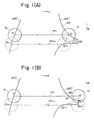
- Figs. 1 and 2 are views for describing the general features of the present invention.
- OFC' denotes an offset curve offset a predetermined amount to the outer side of a closed curve, not shown.
- AR represents an area to undergo surface machining, and TL denotes a tool.
- Arrow A indicates the direction of a cutting path, and arrow B the direction of a shift.
- P i , Q i designate points of intersection, on machining starting point and end point sides, respectively, between the cutting path PT i and offset curve OFC'
- P i+1 , Q i+1 designate points of intersection, on machining end point and starting point sides, respectively, between the cutting path PT i+1 and offset curve OFC'
- R i represents the outermost point of the offset curve between the points of intersection Q i and Q i+1 .
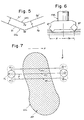
- CCL represents a closed curve
- AR the shaded portion
- OFC designates an offset curve offset to the outer side of the closed curve CCL by the sum of excess thickness T and amount of clearance C.
- OFC' is an offset curve offset to the outer side of the closed curve by (T + C + R), where R is the tool radius.
- Re designates the effective tool radius.
- the arrow A indicates the direction of the cutting path
- arrow B indicates the direction of a shift
- W denotes the width of the area A in the shift direction
- PT i denotes a tool path
- P represents the amount of cut-in.
- this method leaves a portion uncut.
- the points of intersection P i , Q i between the i-th cutting path PT i and the offset curve OFC' offset by (T + C + R) to the outer side of the closed curve specifying the area, as well as the points of intersection P i+1 , Q i+1 between the offset curve OFC' and (i+1)th cutting path PT i+1 , are obtained, where T, C and R represent excess thickness, amount of clearance and tool radius, respectively.
- Surface cutting is then performed by moving the tool TL along the i-th cutting path PT i until coordinate of the position of the tool in the cutting path direction coincides with the coordinate of the point R i .
- uncut portions can be reliably eliminated and tool pass shortened to improve cutting efficiency.
- Fig. 3 is a block diagram of an embodiment of the invention
- Fig. 4 is a flowchart of processing according to the invention. The area cutting method of the invention will now be described with reference to Figs. 1 through 4.
- an area cutting command is inserted into an NC tape in advance, cutting paths are generated successively by using the area cutting data that follow the area cutting command, and surface cutting is performed by moving a tool along the cutting paths.
- the present invention is not limited to such an arrangement.
- An arrangement can be adopted in which after the area data are inputted from a keyboard, an NC tape (NC data) is created through a method substantially the same as that described above and the NC tape is inputted to an NC unit to perform area cutting.
- NC data for tool movement would be prepared.
- tool pass can be shortened.
- the portion can be cut away reliably without leaving portions uncut.
Landscapes
- Engineering & Computer Science (AREA)
- Computing Systems (AREA)
- Theoretical Computer Science (AREA)
- Human Computer Interaction (AREA)
- Manufacturing & Machinery (AREA)
- Physics & Mathematics (AREA)
- General Physics & Mathematics (AREA)
- Automation & Control Theory (AREA)
- Mechanical Engineering (AREA)
- Numerical Control (AREA)
Applications Claiming Priority (2)
| Application Number | Priority Date | Filing Date | Title |
|---|---|---|---|
| JP60160892A JPH0710480B2 (ja) | 1985-07-20 | 1985-07-20 | 面加工方法 |
| JP160892/85 | 1985-07-20 |
Publications (3)
| Publication Number | Publication Date |
|---|---|
| EP0232425A1 EP0232425A1 (en) | 1987-08-19 |
| EP0232425A4 EP0232425A4 (en) | 1989-06-14 |
| EP0232425B1 true EP0232425B1 (en) | 1992-01-22 |
Family
ID=15724618
Family Applications (1)
| Application Number | Title | Priority Date | Filing Date |
|---|---|---|---|
| EP86904394A Expired - Lifetime EP0232425B1 (en) | 1985-07-20 | 1986-07-21 | Surface machining method |
Country Status (6)
| Country | Link |
|---|---|
| US (1) | US4764878A (ja) |
| EP (1) | EP0232425B1 (ja) |
| JP (1) | JPH0710480B2 (ja) |
| KR (1) | KR910007274B1 (ja) |
| DE (1) | DE3683628D1 (ja) |
| WO (1) | WO1987000474A1 (ja) |
Families Citing this family (6)
| Publication number | Priority date | Publication date | Assignee | Title |
|---|---|---|---|---|
| JPH0766290B2 (ja) * | 1986-06-26 | 1995-07-19 | 東芝機械株式会社 | 工具経路生成方法 |
| JP2564488B2 (ja) * | 1987-06-12 | 1996-12-18 | 富士電機株式会社 | 画像塗りつぶし方法 |
| US4989152A (en) * | 1988-11-21 | 1991-01-29 | Cheng Koun Ping | Method of finding the surface intersections and the shortest distance between two aribtrary surfaces |
| JPH06104293B2 (ja) * | 1989-01-30 | 1994-12-21 | 豊田工機株式会社 | 非真円創成制御装置 |
| DE4029607C2 (de) * | 1990-09-19 | 1995-10-26 | Bosch Gmbh Robert | Steuerungsverfahren für die Bewegung eines Fräswerkzeugs zum Fräsen beliebiger zweieinhalbdimensionaler Flächen |
| DE10341776B4 (de) * | 2003-09-10 | 2007-09-27 | P & L Gmbh & Co. Kg | Verfahren zur Bearbeitung eines Werkstücks mittels eines rotierenden, spanabhebenden Werkzeugs |
Family Cites Families (4)
| Publication number | Priority date | Publication date | Assignee | Title |
|---|---|---|---|---|
| JPS6090653A (ja) * | 1983-10-22 | 1985-05-21 | Fanuc Ltd | 領域加工方法 |
| JPS60127952A (ja) * | 1983-12-14 | 1985-07-08 | Fanuc Ltd | 領域加工方法 |
| JPS60127955A (ja) * | 1983-12-14 | 1985-07-08 | Fanuc Ltd | 領域加工方法 |
| JPS60155342A (ja) * | 1984-01-10 | 1985-08-15 | Fanuc Ltd | 領域加工方法 |
-
1985
- 1985-07-20 JP JP60160892A patent/JPH0710480B2/ja not_active Expired - Lifetime
-
1986
- 1986-07-21 KR KR1019870700221A patent/KR910007274B1/ko not_active Expired
- 1986-07-21 US US07/043,350 patent/US4764878A/en not_active Expired - Fee Related
- 1986-07-21 DE DE8686904394Q patent/DE3683628D1/de not_active Expired - Lifetime
- 1986-07-21 WO PCT/JP1986/000380 patent/WO1987000474A1/ja not_active Ceased
- 1986-07-21 EP EP86904394A patent/EP0232425B1/en not_active Expired - Lifetime
Also Published As
| Publication number | Publication date |
|---|---|
| DE3683628D1 (de) | 1992-03-05 |
| JPH0710480B2 (ja) | 1995-02-08 |
| KR910007274B1 (ko) | 1991-09-24 |
| US4764878A (en) | 1988-08-16 |
| JPS6234753A (ja) | 1987-02-14 |
| EP0232425A4 (en) | 1989-06-14 |
| WO1987000474A1 (fr) | 1987-01-29 |
| EP0232425A1 (en) | 1987-08-19 |
| KR870700450A (ko) | 1987-12-29 |
Similar Documents
| Publication | Publication Date | Title |
|---|---|---|
| EP0160097B1 (en) | Area machining method | |
| EP0166784A1 (en) | Area machining method | |
| EP0722580A1 (en) | Motion control with precomputation | |
| EP0160096A1 (en) | Approaching method in area machining | |
| EP0175792B1 (en) | Area machining method | |
| EP0166000B1 (en) | Area machining method | |
| EP0168501B1 (en) | Area machining method | |
| EP0232425B1 (en) | Surface machining method | |
| EP0231388B1 (en) | Surface machining method | |
| EP0161321B1 (en) | Machining method for machine tool | |
| EP0068765B1 (en) | Numerical control method | |
| EP0431174B1 (en) | Involute interpolation error correction system | |
| EP0229851B1 (en) | Region machining method | |
| EP0160705B1 (en) | Machining method for machine tools | |
| EP0436733A1 (en) | Involute interpolation error correction system | |
| EP0519075A1 (en) | Method of forming nc data | |
| US12487575B2 (en) | Control device for industrial machine | |
| JP3343826B2 (ja) | 数値制御情報作成装置 | |
| JP2670180B2 (ja) | 数値制御情報作成装置 | |
| JPS60108249A (ja) | 自由曲面加工用数値制御装置 |
Legal Events
| Date | Code | Title | Description |
|---|---|---|---|
| PUAI | Public reference made under article 153(3) epc to a published international application that has entered the european phase |
Free format text: ORIGINAL CODE: 0009012 |
|
| 17P | Request for examination filed |
Effective date: 19870406 |
|
| AK | Designated contracting states |
Kind code of ref document: A1 Designated state(s): DE FR GB |
|
| A4 | Supplementary search report drawn up and despatched |
Effective date: 19890614 |
|
| 17Q | First examination report despatched |
Effective date: 19910502 |
|
| GRAA | (expected) grant |
Free format text: ORIGINAL CODE: 0009210 |
|
| AK | Designated contracting states |
Kind code of ref document: B1 Designated state(s): DE FR GB |
|
| PG25 | Lapsed in a contracting state [announced via postgrant information from national office to epo] |
Ref country code: FR Effective date: 19920122 |
|
| REF | Corresponds to: |
Ref document number: 3683628 Country of ref document: DE Date of ref document: 19920305 |
|
| EN | Fr: translation not filed | ||
| PG25 | Lapsed in a contracting state [announced via postgrant information from national office to epo] |
Ref country code: GB Effective date: 19920721 |
|
| PLBE | No opposition filed within time limit |
Free format text: ORIGINAL CODE: 0009261 |
|
| STAA | Information on the status of an ep patent application or granted ep patent |
Free format text: STATUS: NO OPPOSITION FILED WITHIN TIME LIMIT |
|
| 26N | No opposition filed | ||
| GBPC | Gb: european patent ceased through non-payment of renewal fee |
Effective date: 19920721 |
|
| PGFP | Annual fee paid to national office [announced via postgrant information from national office to epo] |
Ref country code: DE Payment date: 19970725 Year of fee payment: 12 |
|
| PG25 | Lapsed in a contracting state [announced via postgrant information from national office to epo] |
Ref country code: DE Free format text: LAPSE BECAUSE OF NON-PAYMENT OF DUE FEES Effective date: 19990501 |