EP0235302B1 - Datensammelverfahren für röntgenstrahltomographen - Google Patents
Datensammelverfahren für röntgenstrahltomographen Download PDFInfo
- Publication number
- EP0235302B1 EP0235302B1 EP86905397A EP86905397A EP0235302B1 EP 0235302 B1 EP0235302 B1 EP 0235302B1 EP 86905397 A EP86905397 A EP 86905397A EP 86905397 A EP86905397 A EP 86905397A EP 0235302 B1 EP0235302 B1 EP 0235302B1
- Authority
- EP
- European Patent Office
- Prior art keywords
- channel
- data
- ray
- timing
- channels
- Prior art date
- Legal status (The legal status is an assumption and is not a legal conclusion. Google has not performed a legal analysis and makes no representation as to the accuracy of the status listed.)
- Expired
Links
- 238000000034 method Methods 0.000 title claims abstract description 9
- 230000005540 biological transmission Effects 0.000 claims description 8
- 238000009826 distribution Methods 0.000 claims description 5
- 238000001514 detection method Methods 0.000 abstract 3
- 230000005855 radiation Effects 0.000 description 3
- 238000010521 absorption reaction Methods 0.000 description 2
- 238000013480 data collection Methods 0.000 description 1
- 230000002093 peripheral effect Effects 0.000 description 1
- 238000005070 sampling Methods 0.000 description 1
Images



Classifications
-
- A—HUMAN NECESSITIES
- A61—MEDICAL OR VETERINARY SCIENCE; HYGIENE
- A61B—DIAGNOSIS; SURGERY; IDENTIFICATION
- A61B6/00—Apparatus or devices for radiation diagnosis; Apparatus or devices for radiation diagnosis combined with radiation therapy equipment
- A61B6/02—Arrangements for diagnosis sequentially in different planes; Stereoscopic radiation diagnosis
- A61B6/03—Computed tomography [CT]
- A61B6/032—Transmission computed tomography [CT]
-
- Y—GENERAL TAGGING OF NEW TECHNOLOGICAL DEVELOPMENTS; GENERAL TAGGING OF CROSS-SECTIONAL TECHNOLOGIES SPANNING OVER SEVERAL SECTIONS OF THE IPC; TECHNICAL SUBJECTS COVERED BY FORMER USPC CROSS-REFERENCE ART COLLECTIONS [XRACs] AND DIGESTS
- Y10—TECHNICAL SUBJECTS COVERED BY FORMER USPC
- Y10S—TECHNICAL SUBJECTS COVERED BY FORMER USPC CROSS-REFERENCE ART COLLECTIONS [XRACs] AND DIGESTS
- Y10S378/00—X-ray or gamma ray systems or devices
- Y10S378/901—Computer tomography program or processor
Definitions
- the present invention relates to a method of collecting data for an X-ray tomograph which uses continuous X-rays in the shape of fan beams as referred to in the opening clause of independent claim 1.
- an X-ray source which projects X-rays in the shape of fan beams and a multi-channel X-ray detector which opposes the X-ray source with an object to be examined (hereinunder referred to as "target") interposed therebetween are rotated around the target, so as to project the X-rays in the shape of fan beams along the section of the target, and the data which indicate the distribution of the transmission intensity of the X-rays in a plurality of directions in the section are measured, and the tomogram of the target is reconstructed on the basis of the data.
- the plurality of directions (hereinunder referred to as "view directions") in which the X-ray transmission data are collected are set at the directions obtained by dividing the trajectory of the rotation of the X-ray source and the X-ray detector around the target by an equal angle. These directions are determined by the timing of irradiation when the X-ray is a pulse X-ray, and by the timing for collection of X-ray transmission data when the X-ray is continuous X-rays.
- the reconstruction of the tomogram of the target is carried out on the basis of the respective multi-channel data which have been collected in accordance with a predetermined number of views.
- the collected data are arranged in correspondence with the fan beam X-rays.
- the tomogram of the target may be reconstructed either directly from this arrangement of data, or after the arrangement is converted into the data arrangement which corresponds to parallel beam X-rays.
- the X-ray detector is sometimes disposed so that the central channel thereof is deviated from the X-ray which passes the center of rotation by 1/4 (such a detector will hereinunder be referred to as “offset detector”), and the data on the symmetrical channels of the right half and the left half of the X-ray detector, which have been obtained at angles at which the view directions are substantially opposite, (hereinunder these data will be referred to as "opposing view data”) are combined for reconstruction.
- the opposing view data are also utilized for positively utilizing the duplexity of the data even in an X-ray detector which does not adopt the offset arrangement.
- JP-A-59-77836 discloses a computerized tomograph projection apparatus wherein a radiation source and an array of radiant ray detectors are disposed facing one another with a body that is to be imaged between them. Radiant ray beams radiated from the radiation source spread in a fan shape pass through the imaged body and are incident on the various radiant ray detectors in the radiant ray detector array and, in these conditions, the radiation source and the radiant ray detector array are integrally rotated centring about the imaged body and information relating to the intensity of transmitted radiant rays is gathered from the various radiant ray detectors.
- This information is subjected to image reconstruction processing and the two-dimensional distribution of radiant ray absorptivity in slice planes of the imaged body is reconstructed as a tomographic image.
- a computerized tomograph projection apparatus a high density section in which radiant ray detectors are disposed at fine intervals is provided in the central portion of said radiant ray detector array and low density sections in which radiant ray detectors are disposed at coarse intervals that are odd number multiples of said fine intervals are provided at the peripheral edge portions.
- the position of said radiant ray detector array is shifted with respect to the central axis of rotation by a distance that is 1/4 of the radiant ray detector interval in said high density section multiplied by the odd number.
- JP-A-59-194260 discloses a computerized tomographic apparatus which comprises a first means by which radiant rays are emitted and transmitted through cross-section portions of an examined body. Transmitted image data is obtained as a large number of items of sampling data relating to respective cross-section portions in respect of directions at a large number of angles extending over 0° - 360° around the examined body. Partial reconstruction processing in which the distributions of radiant ray absorption coefficients relating to said cross-section portions are determined is performed and parallel beam reverse projection data is obtained.
- a second means uses the reverse projection data obtained by said first means to reconstruct radiant ray absorption coefficient distribution images relating to said cross-section portions by reverse projection process.
- a computerized tomographic apparatus which is provided with a third means that supplies to said second means data obtained by addition of pairs of data items whose gathering paths are on identical straight lines in each pair of sets of reverse projection data that are in angular directions mutually different by 180 degrees in the group of reverse projection data items.
- These data items constitute the set extending over all the angular directions of reverse projection data in certain angular directions obtained by the first means.
- the computerized tomographic apparatus is so constituted that the data produced by the addition is subjected to reconstruction processing over angular directions of 180° by the second means.
- Fig. 1 is a schematic view of the structure of an embodiment of an X-ray tomograph according to the present invention.
- an X-ray source 2 and a multi-channel X-ray detector 4 are disposed in such a manner as to be opposed to each other with a predetermined positional relationship, and continuous X-rays in the shape of fan beams are projected from the X-ray source 2 to the X-ray detector 4.
- the continuous X-rays may contain a ripple.
- a target 3 mounted on a table 5 is fed to a space between the X-ray source 2 and the X-ray detector 4.
- the X-ray source 2 is controlled by an X-ray source controller 6.
- the gantry 1 is controlled by a gantry and table controller 7 and rotates around the target 3 while maintaining the relative positional relationship between the X-ray source 2 and the X-ray detector 4.
- the table 5 is controlled by the gantry and table controller 7, and positions the target 3 with respect to the gantry 1.
- the X-ray source controller 6 and the gantry and table controller 7 are controlled by a photograph controller 8.
- the X-ray transmission data on a multiplicity of channels detected by the X-ray detector 4 are collected by a data collector 9 by a method which will be explained in detail later, and are converted into digital data to be supplied to a data processor 10.
- the data processor 10 processes the supplied data to reconstruct the tomogram of the target 3, stores the reconstructed image in a large-capacity storage unit 11, at the same time displays it on a display unit 12, and makes the tomogram to be photographed by a photographing device 13, if necessary.
- the data processor 10 controls the photograph controller 8.
- Such an apparatus of the embodiment of the present invention has the structure and the function which are substantially common to a known X-ray tomograph except for the X-ray detector 4 and the data collector 9.
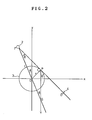
- Fig. 2 shows a geometric relationship between the X-ray source 2 and the X-ray detector 4 in a certain view.
- the rotational position of the gantry is shown by the position of the X-ray source 2. That is, the gantry has rotated from the reference direction O ⁇ Y which is provisionally set, counterclockwise around the center O by the angle ⁇ , so that the view angle is ⁇ , and the X-ray beam which has started from the focal point F distant from the center O by L has passed the point P of the target 3 which is r distant from the center O, and enters one channel D of the X-ray detector 4.
- the angle of the channel D seen from the focal point F is ⁇ with F ⁇ O as the reference.
- the sign of the angle ⁇ is determined to be positive counterclockwise.
- r represents the position of the channel D and ⁇ the angle of the X-ray beam which enters the channel D.
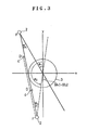
- FIG. 3 A similar geometrical relationship is shown in Fig. 3, in which the channel has a negative ⁇ .
- the X-ray beam is projected to the channel D having the angle ⁇ 1 ( ⁇ 0) at the view angle of ⁇ 1 to obtain X-ray transmission data on the target 3. Since the same data on the target 3 is obtained by the X-ray which passes the same portion of the target in the opposite direction, it is possible to obtain the same data by the channel D' which has the positive angle ⁇ 2 the absolute value of which is equal to ⁇ 1 at the view angle of ⁇ 2.
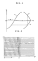
- the upper half of the curve a shows the position of a channel having a positive ⁇
- the lower half of the curve a shows the position of a channel having a negative ⁇ .
- ⁇ obtained from the formula (2) indicates that the portion of the curve in which ⁇ is negative is moved parallel by ⁇
- r in the formula (2) indicates that the sign of the portion of the curve in which ⁇ is negative is reversed. If this is executed in Fig. 4, a curve c is obtained. That is, the portion of the curve a in which ⁇ is negative can be represented by the curve c in which ⁇ is in the positive range.
- the curves a and c are parts of one sine curve.
- a plurality of lines which are parallel to the ⁇ -axis are scales of channels.
- the space between the solid lines and the space between the broken lines represent the channel pitch on the positive ⁇ side and the channel pitch on the negative ⁇ side, respectively.
- a deviation of 1/2 pitch is produced between the scale of the solid line and the scale of the broken line.
- the scale of the solid line and the scale of the broken line are replaced by each other.
- the scale of the solid line agrees with the scale of the broken line.
- view pitch ( ⁇ + 2 ⁇ )/ ⁇ must be an integer, but it is difficult to satisfy the above-described condition with respect to ⁇ of all channels under the condition that the view pitch ⁇ is constant.
- the view position is determined by the timing for collecting channel data in the case of continuous X-rays, and complete opposing view data are collected with respect to all channels by deviating the timing for collecting data on each channel in accordance with the channel angle from the timing for collecting data in the nominal view which is determined in the direction by dividing the trajectory of the rotation of the X-ray source and the X-ray detector around the target by an equal angle ⁇ with one point as the original point.
- the amount of deviation of timing for collecting data on one of the symmetrical channels is assumed to be f( ⁇ )
- the amount of deviation of timing for collecting data on the other channel f(- ⁇ ) is set at an integer. The amount of deviation of timing is determined for each view pitch.
- a number m is provided for a channel of the X-ray detector.
- the number m is so determined that the channel on the extension of the line which connects the focal point of an X-ray and the center of the rotation of the gantry or the channel nearest thereto is 0, and starting from the channel 0, the channels on the positive side are provided with 1, 2, 3..., while the channels on the negative side are provide with -1, -2, -3...
- ⁇ of the opposite data which is to be collected by the opposing channel m' is as follows: The value of b is 1 in the offset detector, and 0 in the non-offset detector. This is because the opposing channel m' is assumed to be situated at an intermediate position between the channel m and the channel m + 1 in the offset detector, while it is assumed to be situated at the position symmetrical to the channel m in the non-offset detector.
- r L sin ⁇ (m + b/2 + a) ⁇ (5)
- the angle ⁇ of the channel m' and the view angle ⁇ are obtained from the formulas (4) and (5) as follows:
- the number of the channel m' for collecting the opposite data is as follows in the offset detector and the non-offset detector, respectively;
- the view angle at this time is represented by the following formula:
- the third term represents the number of the nominal views during a half turn of the gantry and takes a predetermined constant value, but the second term varies in accordance with the channel number m. Accordingly, in order to satisfy the above-described condition, the first term ⁇ g(m) should be set at a value which nullifies the decimal portion of the sum of the second term and the third term in a certain channel number m0, and the value should be varied in accordance with the variation of the second term. Since the value in the second term increases by 2 ⁇ / ⁇ with the increase of 1 in the channel number, the amount of variation in ⁇ g(m) is set at -2 ⁇ / ⁇ so selected as to nullify the increment.
- ⁇ g(m) is the difference in the deviation of the respective timings for collecting a pair of items of opposing view data
- the amount of deviation of one timing and that of the other timing are allocated as desired in the range in which the difference is 2 ⁇ / ⁇ .
- the allocation functions are ⁇ and ⁇
- Fig. 7 shows the arrangement of data on the plane ⁇ - r collected at the above-described timings in a -1/4 offset detector.
- (a) shows the arrangement of the data collected without deviation of timing for comparison with the present invention.
- (b) shows the arrangement of the data collected by deviating one timing. By deviating the timing for collecting the channel data on the negative ⁇ side, these items of data are arranged on the channel data arrangement curves on the positive ⁇ side.
- the opposing view data which have the data arrangement corresponding to the fan beam X-rays and which can be utilized in complete combination with each other are obtained as the real data with respect to all the channels.
- (c) shows the arrangement of the data collected by deviating both timings by the same amount.
- the channel data are arranged on the lines parallel to the r-axis between the respective original channel data arrangement curves.
- the opposing view data which have the data arrangement corresponding to the parallel beam X-rays and which can be utilized in complete combination with each other are obtained as the real data.
- the amount of deviation of the respective timings for collecting the opposing view data may be selected from among the values obtained by varying the same value which has been set so as to have the opposite signs by a constant value.
- Fig. 7 shows the case of using an offset detector, and it is obvious that in the case of using a non-offset detector complete duplex data are obtained as the real data.
- the above-described channel data collection is carried out by the data collector 9 under the control of the data processor 10, and such function of the data collector 9 can be realized by an appropriate sequence control of a known electric circuit for collecting multi-channel X-ray data.
Landscapes
- Health & Medical Sciences (AREA)
- Life Sciences & Earth Sciences (AREA)
- Engineering & Computer Science (AREA)
- Medical Informatics (AREA)
- Radiology & Medical Imaging (AREA)
- Molecular Biology (AREA)
- Biophysics (AREA)
- High Energy & Nuclear Physics (AREA)
- Theoretical Computer Science (AREA)
- Nuclear Medicine, Radiotherapy & Molecular Imaging (AREA)
- Optics & Photonics (AREA)
- Pathology (AREA)
- Pulmonology (AREA)
- Biomedical Technology (AREA)
- Heart & Thoracic Surgery (AREA)
- Physics & Mathematics (AREA)
- Surgery (AREA)
- Animal Behavior & Ethology (AREA)
- General Health & Medical Sciences (AREA)
- Public Health (AREA)
- Veterinary Medicine (AREA)
- Apparatus For Radiation Diagnosis (AREA)
- Analysing Materials By The Use Of Radiation (AREA)
- Image Processing (AREA)
- Image Analysis (AREA)
Claims (3)
- Verfahren zum Sammeln von Daten für einen Röntgenstrahltomographen, bei dem eine Röntgenstrahlenquelle zum Projizieren kontinuierlicher Röntgenstrahlen in Form von Fächerstrahlen und ein Mehrkanal-Röntgenstrahlendetektor, welcher der Röntgenstrahlenquelle mit einem dazwischen eingefügten Untersuchungsobjekt gegenüberliegt, um das Untersuchungsobjekt herum gedreht werden, um damit die Röntgenstrahlen in Form von Fächerstrahlen in einer Anzahl von Blick- oder Sichtrichtungen im Schnitt des Untersuchungsobjekts zu projizieren und das Tomogramm des Untersuchungsobjekts auf der Grundlage der Daten, welche die Verteilung der Durchlässigkeitsintensität der Röntgenstrahlen in jeder Blick- oder Sichtrichtung angeben, zu rekonstruieren, dadurch gekennzeichnet, daß die Richtung einer Nenn-Sicht auf bzw. um einen (Teilkreis-)Einstellwinkel Δφ um den Röntgenstrahlendetektor herum eingestellt wird und daß der Zeitpunkt für das Sammeln jeder Ausgangsdateneinheit der beiden Kanäle, die in im wesentlichen symmetrischen Positionen gegenüber dem Zentrum des Röntgenstrahlendetektors angeordnet sind, von dem durch die Nenn-Sicht vorgeschriebenen Zeitpunkt so verschoben wird, daß die Differenz Δg(m) in der Größe der Verschiebung des Zeitpunkts für das Sammeln von Daten der folgenden Beziehung genügt:

worin bedeuten:Δϑ = (Teilkreis-)Einstellwinkel der Kanäle des Röntgenstrahlendetektors, vom Brennpunkt der Fächerstrahlen aus gesehenm = Nummer der Kanäle, wobei die Nummer des dem Zentrum des Röntgenstrahlendetektors am nächsten gelegenen Kanals gleich 0 ist und die Kanäle auf beiden Seiten mit 1,2,3... bzw. -1,-2,-3... beziffert sinda = Verhältnis des Versatzes eines Punkts, an welchem ein Röntgenstrahl, der von der Röntgenstrahlenquelle ausgegangen ist und das Rotationszentrum passiert hat, in einen Kanal des Röntgenstrahlendetektors eintritt, vom Zentrum des Kanals 0 zum Kanal(teilungs)abstandb = 0, wenn a = 0 oder ± 1/2, oder b = 1, wenn a = ± 1/4n = eine positive ganze Zahl. - Verfahren zum Sammeln von Daten für einen Röntgenstrahltomographen nach Anspruch 1, bei dem die Größe der Verschiebung des Zeitpunkts zum Sammeln von Daten am einen Kanal der beiden Kanäle Δg(m) beträgt und die Größe der Verschiebung des Zeitpunkts zum Sammeln von Daten am anderen Kanal gleich Null ist.
- Verfahren zum Sammeln von Daten für einen Röntgenstrahltomographen nach Anspruch 1, bei dem der Absolutwert der Größe der Verschiebung des Zeitpunkts zum Sammeln von Daten am einen Kanal der beiden Kanäle und der für das Sammeln von Daten am anderen Kanal einander gleich und ihre Vorzeichen zueinander entgegengesetzt sind.
Applications Claiming Priority (2)
| Application Number | Priority Date | Filing Date | Title |
|---|---|---|---|
| JP60191202A JPH0683709B2 (ja) | 1985-08-30 | 1985-08-30 | X線断層撮影装置 |
| JP191202/85 | 1985-08-30 |
Publications (3)
| Publication Number | Publication Date |
|---|---|
| EP0235302A1 EP0235302A1 (de) | 1987-09-09 |
| EP0235302A4 EP0235302A4 (de) | 1989-03-29 |
| EP0235302B1 true EP0235302B1 (de) | 1992-11-11 |
Family
ID=16270604
Family Applications (1)
| Application Number | Title | Priority Date | Filing Date |
|---|---|---|---|
| EP86905397A Expired EP0235302B1 (de) | 1985-08-30 | 1986-08-29 | Datensammelverfahren für röntgenstrahltomographen |
Country Status (5)
| Country | Link |
|---|---|
| US (1) | US4852132A (de) |
| EP (1) | EP0235302B1 (de) |
| JP (1) | JPH0683709B2 (de) |
| DE (1) | DE3687122T2 (de) |
| WO (1) | WO1987001268A1 (de) |
Families Citing this family (13)
| Publication number | Priority date | Publication date | Assignee | Title |
|---|---|---|---|---|
| DE3742716A1 (de) * | 1987-12-14 | 1989-06-22 | Schering Ag | Imidazolderivate ii |
| DE4139150C1 (en) * | 1991-11-28 | 1993-06-24 | Siemens Ag, 8000 Muenchen, De | Computer tomograph with part ring formed X=ray source and detector - has double ring system without complementary interpolation |
| US6173032B1 (en) | 1998-09-29 | 2001-01-09 | General Electric Company | Methods and apparatus for image reconstruction |
| US6324241B1 (en) | 1999-12-30 | 2001-11-27 | Ge Medical Systems Global Technology Company, Llc | Method and apparatus for CT reconstruction |
| US6381297B1 (en) | 2000-08-15 | 2002-04-30 | Ge Medical Systems Global Technology Company, Llc | High pitch reconstruction of multislice CT scans |
| JP3886895B2 (ja) * | 2002-12-27 | 2007-02-28 | ジーイー・メディカル・システムズ・グローバル・テクノロジー・カンパニー・エルエルシー | X線データ収集装置およびx線ct装置 |
| JP2006000225A (ja) * | 2004-06-15 | 2006-01-05 | Canon Inc | X線ct装置 |
| US7215734B2 (en) * | 2004-06-30 | 2007-05-08 | General Electric Company | Method and system for three-dimensional reconstruction of images |
| JP4679348B2 (ja) * | 2005-11-22 | 2011-04-27 | ジーイー・メディカル・システムズ・グローバル・テクノロジー・カンパニー・エルエルシー | X線ct装置 |
| EP2366103B1 (de) * | 2008-10-31 | 2017-12-27 | Analogic Corporation | Messung der position des zentralen detektors zur geometrischen kalibration eines ct-scanners basierend auf einem komplexen phantom |
| CN102613985B (zh) * | 2011-01-31 | 2014-01-22 | 上海西门子医疗器械有限公司 | 一种探测器和包括该探测器的x射线投影数据采集系统 |
| CN102648850B (zh) * | 2011-02-28 | 2014-01-22 | 上海西门子医疗器械有限公司 | 一种x射线投影数据采集系统 |
| CN103961122B (zh) | 2013-01-31 | 2018-07-31 | 通用电气公司 | 用于非等γ角CT系统中数据转换的方法和装置 |
Family Cites Families (9)
| Publication number | Priority date | Publication date | Assignee | Title |
|---|---|---|---|---|
| US4206359A (en) * | 1974-01-31 | 1980-06-03 | E M I Limited | Radiography |
| DE2517440C3 (de) * | 1975-04-19 | 1981-11-19 | Philips Patentverwaltung Gmbh, 2000 Hamburg | Anordnung zur Ermittlung der Absorption einer Strahlung in einer Ebene eines Körpers |
| NL7607976A (nl) * | 1976-07-19 | 1978-01-23 | Optische Ind De Oude Delft Nv | Inrichting voor tomografie met voorzieningen waardoor signaalprofielen afgeleid van een di- vergerende stralingsbundel kunnen worden gere- construeerd in signaalprofielen die elk corre- sponderen met een bundel van evenwijdig inval- lende stralen. |
| JPS5919260A (ja) * | 1982-07-20 | 1984-01-31 | Matsushita Electric Ind Co Ltd | 記録モ−ド判別方式 |
| JPS5977836A (ja) * | 1982-10-25 | 1984-05-04 | 株式会社島津製作所 | コンピユ−タ断層撮影装置 |
| JPS59194260A (ja) | 1983-04-18 | 1984-11-05 | Yokogawa Medical Syst Ltd | 計算機トモグラフイ装置 |
| US4580219A (en) * | 1983-05-02 | 1986-04-01 | General Electric Company | Method for reducing image artifacts due to projection measurement inconsistencies |
| FR2562371A1 (fr) * | 1984-03-30 | 1985-10-04 | Thomson Cgr | Procede de reconstruction d'une image a haute resolution, par tomodensitometrie |
| US4736396A (en) * | 1984-05-29 | 1988-04-05 | Imatron, Inc. | Tomosynthesis using high speed CT scanning system |
-
1985
- 1985-08-29 US US07/050,300 patent/US4852132A/en not_active Expired - Lifetime
- 1985-08-30 JP JP60191202A patent/JPH0683709B2/ja not_active Expired - Lifetime
-
1986
- 1986-08-29 EP EP86905397A patent/EP0235302B1/de not_active Expired
- 1986-08-29 WO PCT/JP1986/000442 patent/WO1987001268A1/ja not_active Ceased
- 1986-08-29 DE DE8686905397T patent/DE3687122T2/de not_active Expired - Lifetime
Also Published As
| Publication number | Publication date |
|---|---|
| JPH0683709B2 (ja) | 1994-10-26 |
| DE3687122D1 (de) | 1992-12-17 |
| WO1987001268A1 (fr) | 1987-03-12 |
| EP0235302A1 (de) | 1987-09-09 |
| US4852132A (en) | 1989-07-25 |
| JPS6249831A (ja) | 1987-03-04 |
| DE3687122T2 (de) | 1993-05-13 |
| EP0235302A4 (de) | 1989-03-29 |
Similar Documents
| Publication | Publication Date | Title |
|---|---|---|
| US5583903A (en) | Computed tomography apparatus | |
| EP0426464B1 (de) | Rechnergesteurtes tomographisches Bildrekonstruktionsverfahren für Spiralabtasten | |
| JP3449561B2 (ja) | X線ct装置 | |
| EP0982603B1 (de) | Verfahren und Vorrichtung zur Ausrichtung eines Detektors in einem Abbildungssystem | |
| US5233518A (en) | Extrapolative reconstruction method for helical scanning | |
| US5291402A (en) | Helical scanning computed tomography apparatus | |
| JP4079472B2 (ja) | マルチ・スライス型計算機式断層写真法システムにおいてx線ビームの位置を決定するシステム | |
| US5377250A (en) | Reconstruction method for helical scanning computed tomography apparatus with multi-row detector array | |
| US3927318A (en) | Cross-sectional fluorescent imaging system | |
| JP4465062B2 (ja) | 計算機式断層写真装置 | |
| US5982846A (en) | Methods and apparatus for dose reduction in a computed tomograph | |
| EP0467532A2 (de) | Rechnergesteuertes Tomographiesystem | |
| JPH0252640A (ja) | X線ctスキャナ装置 | |
| CA2010136A1 (en) | Method for reducing skew image artifacts in helical projection imaging | |
| US6925141B2 (en) | Method for imaging in the computer tomography of a periodically moved object to be examined and CT device for carrying out the method | |
| US4417354A (en) | Diagnostic radiology installation | |
| US4852132A (en) | Method of collecting data for x-ray tomograph | |
| US6343110B1 (en) | Methods and apparatus for submillimeter CT slices with increased coverage | |
| US6118840A (en) | Methods and apparatus to desensitize incident angle errors on a multi-slice computed tomograph detector | |
| US4345158A (en) | Tomographic apparatus for the production of transverse layer images | |
| CA1145068A (en) | Radiation imaging apparatus with a slit collimator | |
| US20230404496A1 (en) | Computed tomography apparatus, manufacturing method thereof and operating method thereof | |
| EP0188782B1 (de) | Sektionsradiographisches Anzeigeverfahren und Vorrichtung dafür | |
| US10602993B2 (en) | Image reconstruction for Z-flying focal spot tomography | |
| Atkins et al. | Absorption edge transmission scanning |
Legal Events
| Date | Code | Title | Description |
|---|---|---|---|
| PUAI | Public reference made under article 153(3) epc to a published international application that has entered the european phase |
Free format text: ORIGINAL CODE: 0009012 |
|
| AK | Designated contracting states |
Kind code of ref document: A1 Designated state(s): DE GB |
|
| 17P | Request for examination filed |
Effective date: 19870902 |
|
| A4 | Supplementary search report drawn up and despatched |
Effective date: 19890329 |
|
| 17Q | First examination report despatched |
Effective date: 19910912 |
|
| GRAA | (expected) grant |
Free format text: ORIGINAL CODE: 0009210 |
|
| AK | Designated contracting states |
Kind code of ref document: B1 Designated state(s): DE GB |
|
| REF | Corresponds to: |
Ref document number: 3687122 Country of ref document: DE Date of ref document: 19921217 |
|
| PLBE | No opposition filed within time limit |
Free format text: ORIGINAL CODE: 0009261 |
|
| STAA | Information on the status of an ep patent application or granted ep patent |
Free format text: STATUS: NO OPPOSITION FILED WITHIN TIME LIMIT |
|
| 26N | No opposition filed | ||
| REG | Reference to a national code |
Ref country code: GB Ref legal event code: IF02 |
|
| PGFP | Annual fee paid to national office [announced via postgrant information from national office to epo] |
Ref country code: GB Payment date: 20050824 Year of fee payment: 20 |
|
| PGFP | Annual fee paid to national office [announced via postgrant information from national office to epo] |
Ref country code: DE Payment date: 20050930 Year of fee payment: 20 |
|
| PG25 | Lapsed in a contracting state [announced via postgrant information from national office to epo] |
Ref country code: GB Free format text: LAPSE BECAUSE OF EXPIRATION OF PROTECTION Effective date: 20060828 |
|
| REG | Reference to a national code |
Ref country code: GB Ref legal event code: PE20 |