EP0642205B1 - Verbindung einer Anschlusslitze einer Bürste in einem elektrischen Motor - Google Patents
Verbindung einer Anschlusslitze einer Bürste in einem elektrischen Motor Download PDFInfo
- Publication number
- EP0642205B1 EP0642205B1 EP94306607A EP94306607A EP0642205B1 EP 0642205 B1 EP0642205 B1 EP 0642205B1 EP 94306607 A EP94306607 A EP 94306607A EP 94306607 A EP94306607 A EP 94306607A EP 0642205 B1 EP0642205 B1 EP 0642205B1
- Authority
- EP
- European Patent Office
- Prior art keywords
- shunt
- terminal
- brush
- assembly
- stator
- Prior art date
- Legal status (The legal status is an assumption and is not a legal conclusion. Google has not performed a legal analysis and makes no representation as to the accuracy of the status listed.)
- Expired - Lifetime
Links
Images




Classifications
-
- H—ELECTRICITY
- H02—GENERATION; CONVERSION OR DISTRIBUTION OF ELECTRIC POWER
- H02K—DYNAMO-ELECTRIC MACHINES
- H02K5/00—Casings; Enclosures; Supports
- H02K5/04—Casings or enclosures characterised by the shape, form or construction thereof
- H02K5/22—Auxiliary parts of casings not covered by groups H02K5/06-H02K5/20, e.g. shaped to form connection boxes or terminal boxes
- H02K5/225—Terminal boxes or connection arrangements
-
- H—ELECTRICITY
- H02—GENERATION; CONVERSION OR DISTRIBUTION OF ELECTRIC POWER
- H02K—DYNAMO-ELECTRIC MACHINES
- H02K3/00—Details of windings
- H02K3/46—Fastening of windings on the stator or rotor structure
- H02K3/52—Fastening salient pole windings or connections thereto
- H02K3/521—Fastening salient pole windings or connections thereto applicable to stators only
- H02K3/522—Fastening salient pole windings or connections thereto applicable to stators only for generally annular cores with salient poles
-
- H—ELECTRICITY
- H02—GENERATION; CONVERSION OR DISTRIBUTION OF ELECTRIC POWER
- H02K—DYNAMO-ELECTRIC MACHINES
- H02K5/00—Casings; Enclosures; Supports
- H02K5/04—Casings or enclosures characterised by the shape, form or construction thereof
- H02K5/14—Means for supporting or protecting brushes or brush holders
- H02K5/143—Means for supporting or protecting brushes or brush holders for cooperation with commutators
- H02K5/148—Slidably supported brushes
Definitions
- This invention relates to electric motors of the type having brushes for commutation. More particularly, this invention relates to a brush/shunt assembly having a stranded shunt and to a method of connecting the brush shunt to a termination point on an electric motor.
- stators typically include a stationary stator portion and a rotor or armature mounted for rotation within the stator.
- the stationary stator portion includes a stator core in which the rotor rotates and may include other stationary parts of the motor such as a frame that holds the ends of the rotor shaft.
- the stator core is either a permanent magnet, which might be a ceramic material, or a material, such as a metal, capable of being magnetized. If the stator core is metallic, it typically includes one or more coils (“field coils" or "stator coils”) wound around the stator core that transform the stator core into an electromagnet when connected to a source of electrical energy.
- the rotor also includes one or more coils (“armature coils” or “rotor coils”) that produce a magnet field in the rotor core when electrical energy is applied.
- the rotor rotates as the magnetic fields in the stator core and the rotor core repel one another.
- a commutator In order to conduct electrical energy to the rotor coils, a commutator is mounted around the rotor shaft.
- the commutator includes two or more commutator bars or rings extending circumferentially around the shaft. Brushes secured to the stator core, or to a support structure attached to the stator core, make sliding contact with the commutator as the rotor rotates.
- a conductor known as a shunt to connect each brush to a termination point on the stationary stator portion, which is also connected either to one of the stator coils or to a source of electrical energy, or both (depending on whether, e.g., the motor is a series-type motor or a shunt-type motor, or a permanent magnet motor as opposed to a motor having stator windings).
- Brushes are typically urged -- e.g., by springs -- toward the commutator so that contact is maintained as the brush wears down.
- the shunt In order for the shunt to be sufficiently flexible so as not to interfere with movement of the brush under the action of the spring, the shunt is frequently made from fine stranded wire, which may be braided or twisted.
- One type of termination that is commonly used to make connections on a stator assembly is a terminal having a slot between two arms that are urged toward one another. A wire is inserted in the slot and is held in place by the arms. The arms also have sharp edges which cut into the surface of the wire, both to cut through any insulation or insulating coating (which is common on wire used for coil windings) and to assure good mechanical and electrical contact.
- uninsulated stranded wire such as brush shunts, because the sharp edges would cut through the strands and the shunt would fail, or at best would achieve poor electrical contact.
- a one-piece terminal having a male quick-disconnect tab on one end and a slotted termination portion on the other end could be mounted on the stator assembly.
- the stator coil would be electrically terminated to the slotted terminal portion.
- a female quick-disconnect terminal could be connected to the end of the shunt, as by crimping, soldering or both.
- the male and female quick-disconnect terminals are then mated to one another. This requires providing (1) an additional terminal on the shunt, (2) a crimping or soldering step, and (3) a terminal mating step.
- the connection of the shunt to the stator thus becomes time-, labor- and material-intensive.
- accessory components are to be electrically connected to the motor circuit -- e.g., if a light bulb for use as a headlight in a powered vacuum cleaner nozzle is to be connected in parallel with the armature coils of the nozzle motor -- it is common to mount an additional terminal on the end of each accessory lead and a mating terminal, electrically connected to the shunt terminal, on the stator assembly.
- a two-into-one adaptor can be attached to the entity stator terminal, to which separate terminals on the ends of the shunt and the accessory lead are both mated. Either approach adds to the cost in time, labor and material.
- a brush/shunt assembly for use in a dynamo-electric machine.
- the assembly comprises a commutator brush and a stranded wire shunt connected at a first end thereof to the brush and having a second end for connection to a terminal on a stationary stator portion of the dynamo-electric machine.
- the stranded wire shunt has the connection end stiffened for insertion into the terminal, preferably by fusing or welding the strands in the connection end together.
- the stiffened end of the shunt is lubricated for insertion into the terminal, as with beeswax or paraffin.
- a motor incorporating the assembly, and a method of connecting such a shunt, are also provided.
- the present invention allows the connection of a stranded wire brush shunt (or any other stranded wire) to a slotted terminal of the type described above.
- a stranded wire brush shunt or any other stranded wire
- additional steps and materials for attaching additional terminals to allow connection of a stranded shunt are eliminated.
- the number of terminals that must be mounted on the stator assembly, where there is limited space, can be reduced by simplifying the connection of accessory leads.
- the strands at the end of a stranded wire shunt are stiffened before the end is inserted into a slotted terminal of the type described above.
- the strands can be stiffened in a number of ways.
- the stranded wire shunt can be securely held at gripping point spaced away from the end to be inserted into the terminal.
- the end can then be grasped and twisted to form a segment, between the end and the gripping point, where the strands are tightly bunched together, effectively forming a more rigid conductor along that segment.
- the end and the gripping point can then continue to be held securely as the segment between them is inserted into the slotted terminal.
- the method of insertion can be simply to move the two gripped points toward the stator after aligning the gripped segment with the slot in the terminal, or a conventional insertion tool designed for such terminals can be used to press the segment into the slot.
- the end of the stranded shunt can be joined together to stiffen the end.
- the ends can be welded together -- i.e., the individual strands at the end can be melted together into a single solid conductor.
- the individual strands can be fused -- i.e., they can be heated just enough that the surfaces of the individual strands adhere to one another, but the individual strands do not lose their separate identities as they do in the case of welding.
- the individual strands could be soldered together at the end of the shunt.
- insertion is preferably carried out with the tool described above, but can be carried out by gripping the shunt at two points as described above.
- Solid wire also known as "magnet wire”
- Such solid wire generally has a smooth round cross section, and the terminal is designed for the insertion resistance that would be encountered with such wire.
- the prepared shunt wire produced by stiffening the strands at the end of a stranded shunt in accordance with the present invention is neither round nor smooth. Rather, the surface is relatively rough or "lumpy,” giving rise to greater resistance to insertion into the terminal. As a result, some of the strands may break on insertion, and higher than expected contact resistance or shunt fatigue failures may also result.
- a lubricant to the stiffened end of the shunt substantially eliminates the insertion resistance.
- the insertion forces needed when a lubricant is used are substantially the same as are required for a standard solid wire.
- a particularly preferred lubricant for this purpose is beeswax. Paraffin is also a preferred lubricant.
- Other lubricants can also be used, but care should be taken that the selected lubricant does not degrade any polymeric components used in the motor, including plastic terminal connectors and wire insulation, and that it does not affect the electrical quality of the connection.
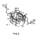
- Motor 10 includes a stator 20 having a core 30 made of a stack of laminations 22, and an armature 21 also having a core made of laminations 22.
- the stator laminations and rotor laminations differ in cross section (not shown).
- armature 21 the laminations 22 are stacked on a shaft 23, the protruding end 11 of which is used to drive a load (not shown).
- bearing 12 is a sleeve bearing.
- the other end of shaft 23 passes through a similar sleeve bearing 24.
- a second bearing housing 14 houses bearing 24 and also has tabs 15 for mounting motor 10 to a device in which it is used. Housing 14 also houses a cooling fan 25 mounted on shaft 23, which forces cooling air through motor 10 as it operates.
- Stator core 30 has two stator or field coils 31, 32 wound in recesses 40 provided in stator core 30 for that purpose.
- Recesses 40 are preferably lined with paper liners 33 (blocking the view of laminations 22 inside portions of core 30) to assist in preventing short circuits between stator coils 31, 32 and stator core 30.
- the portions of stator coils 31, 32 protruding above the top and below the bottom of stator core 30 are held in place by retainers 34, which typically are stiff, paper-covered metallic ribbons.
- stator core 30 Mounted on one end of stator core 30 are two plastic terminal boards 41, preferably made of nylon, each having two terminal pockets 42.
- motor 10 is a series-wound AC motor, in which stator coils 31, 32 are connected in series, with armature coils 27 connected in series between them.
- two of the four terminal pockets 42 house "siamese" terminals 43 having on each end slotted terminals 44 of the type described above (such siamese terminals are available from Amtronics, Inc., of Brooklyn, New York and are sold under the trademark SIAMEZE ® ), and the other two terminal pockets 42 house terminals 45 having the slotted terminal 44 on the lower half and a flag- or tab-type terminal 46 on the upper half (such terminals are also part of the family of products available from Amtronics, Inc. under the trademark SIAMEZE ® ).
- Each of the four stator coil leads 47 is placed in a slot 48 in a respective terminal pocket 42 and the corresponding terminal 43, 45 is then placed in terminal pocket 42 to receive lead 47 in the slot of slotted terminal 44, in a configuration in which one lead of each stator coil 31, 32 is connected to a terminal 43 and the other lead of each stator coil 31, 32 is attached to a terminal 45.
- Armature or rotor 21 has a plurality of armature coils 27 terminated to a commutator 28.
- commutator 28 is segmented into a number of segments 29 equal to twice the number of coils 27 (i.e., one segment 29 for each end of each coil 27).
- the supply of electrical power to motor 10 is connected to the two tabs 46 of the two terminals 45, thereby connecting power to one end of each of stator coils 31, 32.
- brushes 35 are connected by shunts 36 to the upper terminals 44 of each of the two terminals 43.
- Brushes 35 are housed in brush channels 200 of bearing/brush housing 13, and preferably are made of graphite. Brushes 35 are urged in channels 200 toward commutator 28 by springs 201 (only one shown) acting on each respective brush 35 through slot 16 in the wall of each respective channel 200.
- Brush shunts 36 are preferably braided wire shunts, preferably braided from six bundles, each including 25 strands of copper wire, each strand having a diameter of about 0.002 inch (about 0.051 mm). Each shunt 36 is terminated by insertion into the slot 53 of upper slotted terminal 44 of terminal 43, which slot is accessible in slot 48 of a respective terminal pocket 42.
- the insertion of shunt 36 into slot 53 of upper terminal 44 is facilitated by joining the strands in end 360 of shunt 36, to stiffen end 360, in any of the ways described above.
- a coating 361 of lubricant such as, preferably, beeswax or paraffin, is applied preferably to end 360 of shunt 36 to ease insertion of end 360 into terminal 43.
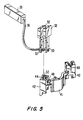
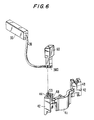
- FIGS. 5 and 6 Two different methods of inserting end 360 into the slot of terminal 44 are shown in FIGS. 5 and 6.
- end 360 is gripped at its extremity 50 and at a second gripping point 51 in appropriate tools 52, and aligned with slot 53 of terminal 44, and the tools 52 are urged downward to insert end 360 into slot 53.
- this gripping can also be the method of stiffening end 360.
- a special tool 60 is used to force end 360 into slot 53.
- FIG. 7 shows a second preferred embodiment of a brush/shunt assembly 70 according to the present invention.
- Brush/shunt assembly 70 include brush 35 and shunt 36 as above.
- shunt 36 of assembly 70 has an end 71 jacketed with a polymeric jacket 72.
- Jacket 72 can be a thermoplastic material such as polyvinyl chloride (PVC).
- PVC polyvinyl chloride
- Jacket 72 can be applied in several ways. First, a bath of the appropriate polymeric substance can be supplied in liquid form. End 71 of brush 36 can be dipped into the bath and cured. Another option is to provide jacket 72 as a preformed tube of shrinkable material which is placed over end 71 and then shrunk to fit tightly onto end 71.
- the shrinkable material is preferably heat-shrinkable and is shrunk by the application of heat, but other types of shrinkable materials may be used.
- jacketing end 71 care should be taken in jacketing end 71 not to jacket any more of shunt 36 than is necessary for insertion into terminal 44. If too much of shunt 36 is jacketed, shunt 36 may lose the flexibility it was designed to have that allows brush 35 to follow the urging of spring 201. On the other hand, jacketing a portion of end 71 provides an extra measure of strain relief as jacket 72 bears much of any load placed on the termination of shunt 36 to terminal 44.
- the slotted terminals 44 under which the present invention is to be cited are ordinarily designed to have one wire lead inserted in each terminal slot 53.
- an additional lead 80 as shown in FIG. 8, if lead 80 is sufficiently small.
- lead 80 were for connection of an accessory device, such as a light bulb (not shown) to be used as the headlight of a powered vacuum cleaner nozzle incorporating motor 10, there should be sufficient room in slot 53 for connection of lead 80.
- lead 80 would have a conductor 81 surrounded by insulating jacket 82.
- a locking staple 83 such as that sold by Amtronics, Inc. under the trademark LEAD-LOK®, is preferably applied.
- a brush/shunt assembly having a joined end, and a motor incorporating the assembly, are provided.
Landscapes
- Engineering & Computer Science (AREA)
- Power Engineering (AREA)
- Motor Or Generator Current Collectors (AREA)
- Manufacture Of Motors, Generators (AREA)
- Motor Or Generator Frames (AREA)
- Insulation, Fastening Of Motor, Generator Windings (AREA)
Claims (31)
- Bürsten/Anschlußlitzen-Einheit zur Verwendung in einer dynamoelektrischen Maschine (1), wobei die Einheit aufweist:eine Kommutatorbürste (35); undeine Anschlußlitze (36), die an einem ersten Ende der Litze mit der Kommutatorbürste (35) verbunden ist und ein zweites Anschlußende (360, 71) zur Verbindung mit einer Anschlußklemme (42) an einem feststehenden Ständerteil (20) der dynamoelektrischen Maschine aufweist, dadurch gekennzeichnet, daß das Anschlußende der Anschlußlitze ein versteiftes Anschlußende zum Einstecken in die Anschlußklemme ist.
- Bürsten/Anschlußlitzen-Einheit nach Anspruch 1, dadurch gekennzeichnet, daß das Anschlußende (71, 360) der Anschlußlitze behandelt wird, um den Widerstand beim Einstecken in die Anschlußklemme (42) zu verringern.
- Einheit nach Anspruch 1, wobei das versteifte Anschlußende (71, 360) der Anschlußlitze durch Schmieren behandelt wird, um den Widerstand beim Einstecken in die Anschlußklemme zu verringern.
- Einheit nach Anspruch 3, wobei das versteifte Ende (360) der Anschlußlitze mit Bienenwachs (361) geschmiert wird.
- Einheit nach Anspruch 3, wobei das versteifte Ende (360) der Anschlußlitze mit Paraffin (361) geschmiert wird.
- Einheit nach einem der Ansprüche 1 bis 5, wobei Litzenenden in der Anschlußlitze (36) versteift werden, indem sie miteinander verbunden werden.
- Einheit nach einem der Ansprüche 6, wobei Litzenenden in dem versteiften Ende (71, 360) der Anschlußlitze miteinander verschweißt werden.
- Einheit nach einem der Ansprüche 1 bis 6, wobei Litzenenden in dem versteiften Ende (71, 360) der Anschlußlitze miteinander verschmolzen werden.
- Einheit nach einem der Ansprüche 1 bis 6, wobei Litzenenden in dem versteiften Ende (71, 360) der Anschlußlitze miteinander verlötet werden.
- Dynamoelektrische Maschine mit mindestens einer Bürsten/Anschlußlitzen-Einheit nach einem der vorstehenden Ansprüche, welche aufweist:einen feststehenden Ständerteil (20) mit einem Ständerpaket (30);einen Anker (21), der drehbar in dem Ständerpaket (30) montiert ist;mindestens eine auf den Anker gewickelte Ankerwicklung;einen an dem Anker (21) montierten Kommutator (29), an dem die mindestens eine Ankerwicklung abgeschlossen wird;mindestens eine an dem Ständer (20) montierte Anschlußklemme (42), wobei die Anschlußklemme ein Paar elektrisch leitender Arme und einen Schlitz (48) zwischen dem Paar elektrisch leitender Arme zur Aufnahme einer Zuleitung aufweist, wobei die Arme eine nach innen gerichtete Kraft auf die Zuleitung ausüben, um die Zuleitung festzuhalten und elektrischen Kontakt mit dieser herzustellen; wobeidie Anschlußlitze(n) (36) jeder der mindestens einen Bürsten/Anschlußlitzen-Einheit(en) die Bürste (35) jeder der mindestens einen Einheit(en) mit der mindestens einen Anschlußklemme (42) verbindet, undwobei beim Zusammenbau der dynamoelektrischen Maschine das versteifte Ende (71, 360) der Anschlußlitze (36) zwischen den elektrisch leitenden Armen der Anschlußklemme (42) eingesteckt wird.
- Dynamoelektrische Maschine nach Anspruch 10, die ferner aufweist:eine Ständerwicklung (31, 32), die auf das Ständerpaket (30) gewickelt ist und zwei Enden (47) aufweist, wobei eines der Enden mit mindestens einer Anschlußklemme (42) elektrisch verbunden ist; undeine zweite Anschlußklemme (42), die an dem Ständerpaket montiert ist, wobei das zweite Ende der Ständerwicklung mit der zweiten Anschlußklemme elektrisch verbunden ist.
- Dynamoelektrische Maschine nach Anspruch 11, die ferner aufweist:eine zweite Bürste (35) zum Kontaktieren des Kommutators;eine an das Ständerpaket montierte dritte Anschlußklemme (42); undeine zweite der mindestens einen Anschlußlitze(n) (36) zum Verbinden der zweiten Bürste mit der dritten Anschlußklemme.
- Dynamoelektrische Maschine nach Anspruch 12, die ferner aufweist:eine zweite Ständerwicklung (31, 32), die auf das Ständerpaket (30) gewickelt ist und zwei Enden (447) aufweist, wobei eines der Enden der zweiten Ständerwicklung mit der dritten Anschlußklemme verbunden ist; undeine an das Ständerpaket montierte vierte Anschlußklemme, wobei ein zweites Ende der zweiten Ständerwicklung mit der vierten Anschlußklemme verbunden ist; wobeidie zweite und die vierte Anschlußklemme für den Anschluß an eine elektrische Stromquelle vorgesehen sind.
- Dynamoelektrische Maschine nach einem der Ansprüche 10 bis 13, wobei die Maschine ein Elektromotor (10) ist, der ferner eine elektrische Lichtquelle mit mindestens einer Zuleitung (80) aufweist, die an eine der entsprechenden Anschlußklemmen (42) angeschlossen ist.
- Elektromotor nach Anspruch 14, der ferner ein Verriegelungselement in dem Schlitz (48) zum Befestigen der einen von den Bürstenanschlußlitzen (36) und der einen von den Zuleitungen (80) in dem Schlitz (48) aufweist.
- Verfahren zur Herstellung einer Bürsten/Anschlußlitzen-Einheit zur Verwendung in einer dynamoelektrischen Maschine, wobei die Einheit aufweist: (i) eine Kommutatorbürste (35) und (ii) eine Anschlußlitze (36), die an einem ersten Ende der Litze mit der Kommutatorbürste verbunden ist und ein zweites Ende (71, 360) für den Anschluß an eine Anschlußklemme (42) an einem Ständer (20) einer dynamoelektrischen Maschine aufweist, wobei das zweite Ende (71, 360) der Anschlußlitze zum Einstecken in die Anschlußklemme (42) versteift wird, wobei das Verfahren die folgenden Schritte aufweist:Bereitstellen der Kommutatorbürste und der damit verbundenen Anschlußlitze; undVersteifen des zweiten Endes der Anschlußlitze.
- Verfahren nach Anspruch 16, das ferner den Schritt zum Behandeln des zweiten Endes der Anschlußlitze zur Verringerung des Widerstandes beim Einstecken in die Anschlußklemme aufweist.
- Verfahren nach Anspruch 17, wobei der Behandlungsschritt das Aufbringen eines Schmiermittels auf das zweite Ende der Anschlußlitze aufweist.
- Verfahren nach Anspruch 18, wobei der Aufbringungsschritt das Aufbringen von Bienenwachs auf das zweite Ende der Anschlußlitze aufweist.
- Verfahren nach Anspruch 18, wobei der Aufbringungsschritt das Aufbringen von Paraffin auf das zweite Ende der Anschlußlitze aufweist.
- Verfahren zum Zusammenbau einer dynamoelektrischen Maschine, wobei die dynamoelektrische Maschine aufweist: (i) einen feststehenden Ständerteil (20) mit einem Ständerpaket, (ii) einen drehbaren Anker (21), der innerhalb des Ständerpakets drehbar montiert ist, (iii) mindestens eine auf den Anker gewickelte Ankerwicklung, einen Kommutator (29) an dem Anker, an dem die mindestens eine Ankerwicklung angeschlossen wird, (iv) mindestens eine Bürste (35) zum Kontaktieren des Kommutators, und (v) jeweils eine Anschlußlitze (36) zum elektrischen Verbinden jeder der mindestens einen Bürste(n) an einem proximalen Ende der Anschlußlitze mit einer entsprechenden Anschlußstelle (42) an dem feststehenden Ständerteil an einem distalen Ende der Anschlußlitze, wobei das Verfahren aufweist:Herstellen einer Bürsten/Anschlußlitzen-Einheit nach einem der Ansprüche 16 bis 20;Bereitstellen einer Schlitzklemme (42) mit einem Schlitz (48) als der entsprechenden Anschlußstelle zur Aufnahme des distalen Endes zwischen einem Paar elektrisch leitender Arme, wobei die Arme eine nach innen gerichtete Kraft auf das distale Ende ausüben, um die eine der Bürstenanschlußlitzen festzuhalten und einen elektrischen Kontakt zu ihr herzustellen; undEinstecken der versteiften Litzen in den Schlitz (48) zwischen den leitfähigen Armen.
- Verfahren nach Anspruch 21, wobeider Versteifungsschritt das feste Einspannen einer der Anschlußlitzen (36) an einer ersten Einspannstelle (50) an dem distalen Ende zum Zusammenhalten der Litzen aufweist; undwobei der Einsteckschritt aufweist:Einspannen der einen von den Anschlußlitzen an einer zweiten, von dem distalen Ende entfernten Einspannstelle (51), um einen eingespannten Abschnitt zwischen der ersten und der zweiten Einspannstelle (50, 51) zu bilden;Positionieren des eingespannten Abschnitts angrenzend an den Schlitz (48); undDrücken beider Einspannstellen zum Ständerteil (20) hin, um den eingespannten Abschnitt in den Schlitz (48) hineinzudrücken.
- Verfahren nach Anspruch 21, wobeider Versteifungsschritt das Verbinden von Litzenenden aufweist, so daß diese aneinanderhaften, um ein verbundenes Ende (71, 360) zu bilden; undwobei der Einsteckschritt aufweist:Positionieren des verbundenen Endes angrenzend an den Schlitz (48) und Drücken des verbundenen Endes zum Ständerpaket hin, um das verbundene Ende in den Schlitz einzusetzen.
- Verfahren nach Anspruch 23, wobei der Verbindungsschritt das Verschweißen der Litzenenden aufweist.
- Verfahren nach Anspruch 23, wobei der Verbindungsschritt das Verschmelzen der Litzenenden aufweist.
- Verfahren nach Anspruch 23, wobei der Verbindungsschritt das Verlöten der Litzenenden aufweist.
- Verfahren nach einem der Ansprüche 21 bis 26, wobei der Einsteckschritt ferner das Schmieren der versteiften Litzen vor dem Einstecken aufweist.
- Verfahren nach Anspruch 27, wobei der Schmierschritt das Schmieren der versteiften Litzen mit Bienenwachs aufweist.
- Verfahren nach Anspruch 27, wobei der Schmierschritt das Schmieren der versteiften Litzen mit Paraffin aufweist.
- Verfahren zum Zusammenbau eines Elektromotors nach einem der Ansprüche 21 bis 29, wobei der Elektromotor eine elektrische Lichtquelle mit mindestens einer Zuleitung (80) aufweist, die an die entsprechende Anschlußstelle (42) angeschlossen ist, wobei das Verfahren ferner aufweist:
Einstecken der einen von den Lichtquellenzuleitungen (80) in den Schlitz (48) zwischen den leitfähigen Armen. - Verfahren nach Anspruch 30, das ferner das Befestigen der einen von den Bürstenanschlußlitzen und der einen von den Zuleitungen (80) in dem Schlitz durch Anbringen eines Verriegelungselements an dem Schlitz (48) nach dem Einstecken der einen von den Anschlußlitzen und der einen von den Zuleitungen aufweist.
Applications Claiming Priority (2)
| Application Number | Priority Date | Filing Date | Title |
|---|---|---|---|
| US08/118,129 US5465016A (en) | 1993-09-08 | 1993-09-08 | Electric motor and brush/shunt assembly therefor |
| US118129 | 1993-09-08 |
Publications (3)
| Publication Number | Publication Date |
|---|---|
| EP0642205A2 EP0642205A2 (de) | 1995-03-08 |
| EP0642205A3 EP0642205A3 (de) | 1995-07-19 |
| EP0642205B1 true EP0642205B1 (de) | 1997-12-03 |
Family
ID=22376663
Family Applications (1)
| Application Number | Title | Priority Date | Filing Date |
|---|---|---|---|
| EP94306607A Expired - Lifetime EP0642205B1 (de) | 1993-09-08 | 1994-09-08 | Verbindung einer Anschlusslitze einer Bürste in einem elektrischen Motor |
Country Status (8)
| Country | Link |
|---|---|
| US (1) | US5465016A (de) |
| EP (1) | EP0642205B1 (de) |
| JP (1) | JPH0787715A (de) |
| CA (1) | CA2130687C (de) |
| CZ (1) | CZ217194A3 (de) |
| DE (1) | DE69407119T2 (de) |
| ES (1) | ES2112487T3 (de) |
| PL (1) | PL304977A1 (de) |
Families Citing this family (26)
| Publication number | Priority date | Publication date | Assignee | Title |
|---|---|---|---|---|
| US6106324A (en) * | 1995-07-26 | 2000-08-22 | Dana Corporation | Programmable termination strip for electric motor |
| IT240886Y1 (it) * | 1996-09-17 | 2001-04-11 | Wimer S R L | Connettore per motori elettrici,in particolare per motori elettricidi macchine lavatrici ed elettrodomestici in genere |
| US6300698B1 (en) * | 1999-10-22 | 2001-10-09 | Emerson Electric Co. | Hermetic compressor and an electrical connector therefor |
| US8141231B2 (en) * | 2003-09-15 | 2012-03-27 | Shop Vac | Electric motor |
| JP2005229755A (ja) * | 2004-02-13 | 2005-08-25 | Toyota Motor Corp | モータモジュール |
| JP4559747B2 (ja) * | 2004-02-13 | 2010-10-13 | トヨタ自動車株式会社 | モータモジュール |
| JP2006210104A (ja) * | 2005-01-27 | 2006-08-10 | Denso Corp | 回転電機用カーボンブラシ |
| JP2006238588A (ja) * | 2005-02-24 | 2006-09-07 | Nidec Sankyo Corp | リニアアクチュエータ、それを用いたポンプ装置並びにコンプレッサー装置 |
| US7465606B2 (en) * | 2005-10-04 | 2008-12-16 | Brose Fahrzeugteile Gmbh & Co. Kommanditgesellschaft, Wurzburg | Resistance welded solder crimp for joining stranded wire to a copper lead-frame |
| DE102005060358A1 (de) * | 2005-12-16 | 2007-06-21 | BSH Bosch und Siemens Hausgeräte GmbH | Statorendscheibe für einen Kommutatormotor und Kommutatormotor |
| US7518274B1 (en) * | 2006-06-12 | 2009-04-14 | Mancl Dennis J | Motor bracket with integral terminals |
| US8732896B2 (en) | 2006-10-17 | 2014-05-27 | Mtd Products Inc | Hybrid electric cleaning device |
| WO2008048618A2 (en) | 2006-10-17 | 2008-04-24 | Desa Ip. Llc | Hybrid electric device |
| US7884560B2 (en) * | 2006-10-17 | 2011-02-08 | Mtd Products Inc | Hybrid electric device |
| ITPD20060394A1 (it) * | 2006-10-24 | 2008-04-25 | Inarca Spa | Gruppo di connessione degli avvolgimenti statorici di un motore elettrico |
| US8076873B1 (en) | 2007-06-01 | 2011-12-13 | Mtd Products Inc | Hybrid outdoor power equipment |
| US7874816B2 (en) * | 2007-09-28 | 2011-01-25 | Delphi Technologies, Inc. | Fuel pump end cap with isolated shunt wires |
| KR101013781B1 (ko) * | 2009-01-19 | 2011-02-14 | 뉴모텍(주) | 모터 |
| WO2015149841A1 (en) * | 2014-03-31 | 2015-10-08 | Arcelik Anonim Sirketi | Household appliance electric motor terminal direct socket connection structure |
| US9601967B2 (en) | 2014-05-02 | 2017-03-21 | The Scott Fetzer Company | Electric motor brush apparatus and method |
| US9707580B1 (en) | 2015-01-03 | 2017-07-18 | Dennis J. Mancl | High voltage fan motor powered by low voltage |
| CN113299410A (zh) * | 2015-04-10 | 2021-08-24 | 芙罗服务管理公司 | 操作核反应堆的方法和用在其流体系统的阀上的阀促动器 |
| DE102017207265A1 (de) * | 2017-04-28 | 2018-10-31 | Schunk Carbon Technology Gmbh | Messvorrichtung und Verfahren zur Messung eines Verschleißzustandes |
| US10840781B2 (en) * | 2018-09-25 | 2020-11-17 | Dennis J. Mancl | Commutator brush and rolled-up spring assembly |
| DE102020215910A1 (de) * | 2020-12-15 | 2022-06-15 | Valeo Siemens Eautomotive Germany Gmbh | Anschlusseinheit für einen Stator, Statoranordnung für eine elektrische Maschine, Verfahren zur Herstellung einer Statoranordnung und elektrische Maschine zum Antreiben eines Fahrzeugs |
| DE102020215908A1 (de) * | 2020-12-15 | 2022-06-15 | Valeo Siemens Eautomotive Germany Gmbh | Anschlusseinheit für einen Stator, Stator für eine elektrische Maschine, Statoranordnung, Verfahren zur Herstellung einer Statoranordnung und elektrische Maschine zum Antreiben eines Fahrzeugs |
Family Cites Families (49)
| Publication number | Priority date | Publication date | Assignee | Title |
|---|---|---|---|---|
| US599781A (en) * | 1898-03-01 | Current-collecting device | ||
| US2188809A (en) * | 1936-03-03 | 1940-01-30 | Air Way Electric Appl Corp | Vacuum cleaner |
| US2914689A (en) * | 1957-09-24 | 1959-11-24 | Electrolux Corp | Motor brush assembly |
| US3979615A (en) * | 1975-02-05 | 1976-09-07 | Amp Incorporated | Field assembly for electric motors |
| US4038573A (en) * | 1975-04-21 | 1977-07-26 | General Signal Corporation | Coil terminating means |
| GB1519421A (en) * | 1976-02-18 | 1978-07-26 | Trico Folberth Ltd | Brush mountings |
| US4059776A (en) * | 1976-04-19 | 1977-11-22 | Stackpole Carbon Company | Electric motor brush mounting |
| US4190781A (en) * | 1977-08-24 | 1980-02-26 | Black & Decker Inc. | Brush system for a portable electric tool |
| US4132460A (en) * | 1977-11-07 | 1979-01-02 | Amp Incorporated | Electrical connections to coil windings |
| US4163167A (en) * | 1977-12-02 | 1979-07-31 | Stackpole Carbon Company | Electric motor brush holder |
| US4177397A (en) * | 1978-03-17 | 1979-12-04 | Amp Incorporated | Electrical connections for windings of motor stators |
| JPS5615148A (en) * | 1979-07-17 | 1981-02-13 | Matsushita Electric Ind Co Ltd | Connecting method of stator winding of motor |
| US4250613A (en) * | 1979-08-27 | 1981-02-17 | Black & Decker Inc. | Method of assembling a commutator brush system |
| US4266843A (en) * | 1979-09-24 | 1981-05-12 | The Bendix Corporation | Insulation displacing electrical contact and method of making same |
| US4322647A (en) * | 1979-11-23 | 1982-03-30 | The Scott & Fetzer Company | Motor assembly |
| FR2493060A1 (fr) * | 1980-10-23 | 1982-04-30 | Ducellier & Cie | Element d'immobilisation de shunts de balais de machines electriques |
| US4498230A (en) * | 1982-01-08 | 1985-02-12 | Black & Decker Inc. | Assembling brush box sub-assemblies in electric motors |
| NL8200652A (nl) * | 1982-02-18 | 1983-09-16 | Skil Nederland Nv | Elektromotor met verbeterde borstelkonstruktie. |
| DE3220877A1 (de) * | 1982-06-03 | 1983-12-08 | Vorwerk & Co Interholding Gmbh, 5600 Wuppertal | Buerstenhalterung an mit entstoerdrossel ausgestatteten elektromotoren, insbesondere fuer haushaltsgeraete wie staubsauger oder dergleichen |
| US4469967A (en) * | 1982-06-07 | 1984-09-04 | Whirlpool Corporation | Electric motor coil-retaining means |
| JPS598256U (ja) * | 1982-07-01 | 1984-01-19 | アルプス電気株式会社 | 小型モ−タのブラシ取付構造 |
| US4523116A (en) * | 1983-03-31 | 1985-06-11 | Black & Decker, Inc. | Electrical connection system for motors |
| JPS6032549A (ja) * | 1983-07-30 | 1985-02-19 | Asmo Co Ltd | 整流子と電機子巻線との接合方法 |
| US4613781A (en) * | 1983-09-09 | 1986-09-23 | Black & Decker Inc. | End cap assembly and brush box an electric motor |
| JPS6059948A (ja) * | 1983-09-12 | 1985-04-06 | Mitsubishi Electric Corp | 回転電機のコイル絶縁処理方法 |
| US4513214A (en) * | 1983-10-03 | 1985-04-23 | Allied Corporation | Dynamoelectric machine |
| JPH0636659B2 (ja) * | 1984-03-02 | 1994-05-11 | 株式会社日立製作所 | 回転電機用固定子 |
| US4617486A (en) * | 1984-04-19 | 1986-10-14 | S. M. C. Co., Ltd. | Miniature D.C. motor with improved terminal plate and brushes |
| US4673837A (en) * | 1984-05-11 | 1987-06-16 | Amp Incorporated | Motor brush assembly |
| US4677329A (en) * | 1984-07-12 | 1987-06-30 | Black & Decker, Inc. | Sub-assembly for electric motor with stator terminal connection means |
| JPS61154444A (ja) * | 1984-12-27 | 1986-07-14 | Toshiba Corp | 回転電機の巻線挿入方法及びその装置 |
| US4621991A (en) * | 1985-02-22 | 1986-11-11 | Ametek, Inc. | Quiet by-pass vacuum motor |
| US4698534A (en) * | 1985-02-22 | 1987-10-06 | Ametek, Inc. | Quiet by-pass vacuum motor |
| US4801833A (en) * | 1985-12-12 | 1989-01-31 | Eaton Stamping Company | Motor end cap |
| ES291075Y (es) * | 1985-12-17 | 1988-04-16 | Braun Espanola,S.A. | Dispositivo puente escobillas para utilizacion en motores electricos de colector |
| US4749365A (en) * | 1987-01-09 | 1988-06-07 | George Magnifico | Insulation displacement terminal |
| JPH0782937B2 (ja) * | 1987-05-28 | 1995-09-06 | 株式会社東芝 | 超電導コイルの製造方法 |
| US4782261A (en) * | 1987-08-11 | 1988-11-01 | Shop-Vac Corporation | Connection of motor brush holder to stator coil |
| US4868441A (en) * | 1988-07-11 | 1989-09-19 | Ford Motor Company | Brush holder assembly |
| JPH0239916A (ja) * | 1988-07-29 | 1990-02-08 | Toshiba Corp | 耐熱性熱収縮チューブの製造方法 |
| JPH02110974U (de) * | 1989-02-22 | 1990-09-05 | ||
| JPH0732569B2 (ja) * | 1989-08-31 | 1995-04-10 | 株式会社三ツ葉電機製作所 | 電動モータにおける刷子ホルダの構造および該刷子ホルダ製造用の金型構造 |
| FR2651615B1 (fr) * | 1989-09-05 | 1991-10-25 | Valeo Systemes Dessuyage | Dispositif porte-balais pour moteurs electriques a collecteur tournant. |
| GB2244385B (en) * | 1990-05-30 | 1995-01-04 | Mitsuba Electric Mfg Co | Brush holder stay of dynamic electric machine |
| US5055728A (en) * | 1990-08-09 | 1991-10-08 | Ryobi Motor Products Corp. | Motor assembly with combined armature shaft bearing support and brush tube holder |
| DE4134070A1 (de) * | 1991-02-18 | 1992-08-20 | Boockmann Gmbh | Verfahren und vorrichtung zum gleitfaehigmachen eines drahtes |
| US5184041A (en) * | 1991-03-12 | 1993-02-02 | Shop Vac Corporation | Structure for coupling field windings to motor brushes |
| US5309054A (en) * | 1992-01-31 | 1994-05-03 | Mitsubishi Denki Kabushiki Kaisha | Leading-out device for a lead wire of a DC motor and a method of leading out a lead wire |
| JPH074057B2 (ja) * | 1992-07-09 | 1995-01-18 | 株式会社東芝 | 回転電機用の鉄心スロット絶縁紙 |
-
1993
- 1993-09-08 US US08/118,129 patent/US5465016A/en not_active Expired - Lifetime
-
1994
- 1994-08-23 CA CA002130687A patent/CA2130687C/en not_active Expired - Lifetime
- 1994-09-07 JP JP6214083A patent/JPH0787715A/ja active Pending
- 1994-09-07 CZ CZ942171A patent/CZ217194A3/cs unknown
- 1994-09-08 EP EP94306607A patent/EP0642205B1/de not_active Expired - Lifetime
- 1994-09-08 ES ES94306607T patent/ES2112487T3/es not_active Expired - Lifetime
- 1994-09-08 DE DE69407119T patent/DE69407119T2/de not_active Expired - Fee Related
- 1994-09-08 PL PL94304977A patent/PL304977A1/xx unknown
Also Published As
| Publication number | Publication date |
|---|---|
| DE69407119D1 (de) | 1998-01-15 |
| CA2130687A1 (en) | 1995-03-09 |
| CA2130687C (en) | 1998-08-25 |
| EP0642205A3 (de) | 1995-07-19 |
| US5465016A (en) | 1995-11-07 |
| PL304977A1 (en) | 1995-03-20 |
| CZ217194A3 (en) | 1995-03-15 |
| JPH0787715A (ja) | 1995-03-31 |
| EP0642205A2 (de) | 1995-03-08 |
| ES2112487T3 (es) | 1998-04-01 |
| DE69407119T2 (de) | 1998-04-09 |
Similar Documents
| Publication | Publication Date | Title |
|---|---|---|
| US5465016A (en) | Electric motor and brush/shunt assembly therefor | |
| US8294328B2 (en) | Brush gear of a motor | |
| US4642885A (en) | Method of assembling a stator | |
| US4544856A (en) | Dynamoelectric machine and stator | |
| US4071793A (en) | Field subassembly for electric motors | |
| US6057626A (en) | Commutator for a dynamo-electric machine and method of manufacture therefor | |
| EP0714159A2 (de) | Läufer für einen Elektromotor | |
| US6941638B2 (en) | Interconnecting method for segmented stator electric machines | |
| US8049391B2 (en) | Electric motor | |
| CN1063290C (zh) | 电机的组装方法及该电机上的接触器 | |
| US4835430A (en) | Commutator connection in an electric motor | |
| EP0829944A3 (de) | Verbinder für Elektromotoren, insbesondere für Elektromotoren für Waschautomaten und elektrische Haushaltsgerät im allgemeinen | |
| US7317269B2 (en) | Low voltage electronic motor wire termination | |
| JP3866427B2 (ja) | アウタロータ型多極発電機用ステータ | |
| GB2205451A (en) | Connecting brush holders and suppression element to stator windings of an electric motor | |
| EP0822642B1 (de) | Gleichrichter für einen Wechselstromgenerator, insbesondere für Kraftfahrzeuge | |
| CN218513698U (zh) | 用于无刷电机的连接结构和无刷电机 | |
| US5149999A (en) | Power tool with improved internal wiring structure | |
| EP0463889B1 (de) | Elektrisch betriebenes Werkzeug | |
| US5153474A (en) | Plug in brush retainer for a fractional horsepower electric motor | |
| GB2203292A (en) | Suppressor connection for commutator segment | |
| KR20250008266A (ko) | Bldc 모터 권선 연결 구조 | |
| GB2222319A (en) | Attaching commutator segments | |
| JP3887098B2 (ja) | ステータにおける外部導線接続構造 | |
| CA1226614A (en) | Stator, methods of assembling a stator with a terminal assembly therefore, and a dynamoelectric machine |
Legal Events
| Date | Code | Title | Description |
|---|---|---|---|
| PUAI | Public reference made under article 153(3) epc to a published international application that has entered the european phase |
Free format text: ORIGINAL CODE: 0009012 |
|
| AK | Designated contracting states |
Kind code of ref document: A2 Designated state(s): CH DE ES FR GB IT LI NL |
|
| PUAL | Search report despatched |
Free format text: ORIGINAL CODE: 0009013 |
|
| AK | Designated contracting states |
Kind code of ref document: A3 Designated state(s): CH DE ES FR GB IT LI NL |
|
| 17P | Request for examination filed |
Effective date: 19950831 |
|
| 17Q | First examination report despatched |
Effective date: 19960529 |
|
| GRAG | Despatch of communication of intention to grant |
Free format text: ORIGINAL CODE: EPIDOS AGRA |
|
| GRAH | Despatch of communication of intention to grant a patent |
Free format text: ORIGINAL CODE: EPIDOS IGRA |
|
| GRAH | Despatch of communication of intention to grant a patent |
Free format text: ORIGINAL CODE: EPIDOS IGRA |
|
| GRAA | (expected) grant |
Free format text: ORIGINAL CODE: 0009210 |
|
| AK | Designated contracting states |
Kind code of ref document: B1 Designated state(s): CH DE ES FR GB IT LI NL |
|
| REG | Reference to a national code |
Ref country code: CH Ref legal event code: EP |
|
| REF | Corresponds to: |
Ref document number: 69407119 Country of ref document: DE Date of ref document: 19980115 |
|
| REG | Reference to a national code |
Ref country code: CH Ref legal event code: NV Representative=s name: BOVARD AG PATENTANWAELTE |
|
| ET | Fr: translation filed | ||
| ITF | It: translation for a ep patent filed | ||
| REG | Reference to a national code |
Ref country code: ES Ref legal event code: FG2A Ref document number: 2112487 Country of ref document: ES Kind code of ref document: T3 |
|
| PG25 | Lapsed in a contracting state [announced via postgrant information from national office to epo] |
Ref country code: GB Free format text: LAPSE BECAUSE OF NON-PAYMENT OF DUE FEES Effective date: 19980908 |
|
| PG25 | Lapsed in a contracting state [announced via postgrant information from national office to epo] |
Ref country code: ES Free format text: LAPSE BECAUSE OF NON-PAYMENT OF DUE FEES Effective date: 19980909 |
|
| PG25 | Lapsed in a contracting state [announced via postgrant information from national office to epo] |
Ref country code: LI Free format text: LAPSE BECAUSE OF NON-PAYMENT OF DUE FEES Effective date: 19980930 Ref country code: CH Free format text: LAPSE BECAUSE OF NON-PAYMENT OF DUE FEES Effective date: 19980930 |
|
| PLBE | No opposition filed within time limit |
Free format text: ORIGINAL CODE: 0009261 |
|
| STAA | Information on the status of an ep patent application or granted ep patent |
Free format text: STATUS: NO OPPOSITION FILED WITHIN TIME LIMIT |
|
| 26N | No opposition filed | ||
| PG25 | Lapsed in a contracting state [announced via postgrant information from national office to epo] |
Ref country code: NL Free format text: LAPSE BECAUSE OF NON-PAYMENT OF DUE FEES Effective date: 19990401 |
|
| GBPC | Gb: european patent ceased through non-payment of renewal fee |
Effective date: 19980908 |
|
| REG | Reference to a national code |
Ref country code: CH Ref legal event code: PL |
|
| PG25 | Lapsed in a contracting state [announced via postgrant information from national office to epo] |
Ref country code: FR Free format text: LAPSE BECAUSE OF NON-PAYMENT OF DUE FEES Effective date: 19990531 |
|
| NLV4 | Nl: lapsed or anulled due to non-payment of the annual fee |
Effective date: 19990401 |
|
| PG25 | Lapsed in a contracting state [announced via postgrant information from national office to epo] |
Ref country code: DE Free format text: LAPSE BECAUSE OF NON-PAYMENT OF DUE FEES Effective date: 19990701 |
|
| REG | Reference to a national code |
Ref country code: FR Ref legal event code: ST |
|
| REG | Reference to a national code |
Ref country code: ES Ref legal event code: FD2A Effective date: 19991013 |
|
| PG25 | Lapsed in a contracting state [announced via postgrant information from national office to epo] |
Ref country code: IT Free format text: LAPSE BECAUSE OF NON-PAYMENT OF DUE FEES Effective date: 20050908 |