EP0239153A2 - Procédé et dispositif pour égalisation adaptative aveugle - Google Patents
Procédé et dispositif pour égalisation adaptative aveugle Download PDFInfo
- Publication number
- EP0239153A2 EP0239153A2 EP87200400A EP87200400A EP0239153A2 EP 0239153 A2 EP0239153 A2 EP 0239153A2 EP 87200400 A EP87200400 A EP 87200400A EP 87200400 A EP87200400 A EP 87200400A EP 0239153 A2 EP0239153 A2 EP 0239153A2
- Authority
- EP
- European Patent Office
- Prior art keywords
- accordance
- blind equalization
- adaptive blind
- signal
- decided
- Prior art date
- Legal status (The legal status is an assumption and is not a legal conclusion. Google has not performed a legal analysis and makes no representation as to the accuracy of the status listed.)
- Granted
Links
- 230000003044 adaptive effect Effects 0.000 title claims abstract description 67
- 238000000034 method Methods 0.000 title claims abstract description 65
- 230000006978 adaptation Effects 0.000 claims abstract description 27
- 238000004364 calculation method Methods 0.000 claims description 31
- 230000005540 biological transmission Effects 0.000 claims description 22
- 238000011084 recovery Methods 0.000 claims description 9
- 239000000969 carrier Substances 0.000 claims description 5
- 230000001360 synchronised effect Effects 0.000 claims description 3
- 230000008054 signal transmission Effects 0.000 claims 3
- 238000011144 upstream manufacturing Methods 0.000 claims 3
- 239000000284 extract Substances 0.000 claims 2
- 230000006870 function Effects 0.000 description 20
- 238000004891 communication Methods 0.000 description 5
- 230000008901 benefit Effects 0.000 description 4
- 230000000875 corresponding effect Effects 0.000 description 4
- 238000000926 separation method Methods 0.000 description 4
- 238000004422 calculation algorithm Methods 0.000 description 3
- 238000012937 correction Methods 0.000 description 3
- 238000010586 diagram Methods 0.000 description 3
- 238000005070 sampling Methods 0.000 description 3
- 230000008859 change Effects 0.000 description 2
- 238000010276 construction Methods 0.000 description 2
- 101150073669 NCAN gene Proteins 0.000 description 1
- 230000006399 behavior Effects 0.000 description 1
- 239000003990 capacitor Substances 0.000 description 1
- 238000006243 chemical reaction Methods 0.000 description 1
- 238000005094 computer simulation Methods 0.000 description 1
- 230000001143 conditioned effect Effects 0.000 description 1
- 238000007796 conventional method Methods 0.000 description 1
- 230000002596 correlated effect Effects 0.000 description 1
- 230000009977 dual effect Effects 0.000 description 1
- 230000006872 improvement Effects 0.000 description 1
- 238000004519 manufacturing process Methods 0.000 description 1
- 238000005457 optimization Methods 0.000 description 1
- 238000012887 quadratic function Methods 0.000 description 1
- 230000001105 regulatory effect Effects 0.000 description 1
- 230000004044 response Effects 0.000 description 1
Images


Classifications
-
- H—ELECTRICITY
- H04—ELECTRIC COMMUNICATION TECHNIQUE
- H04L—TRANSMISSION OF DIGITAL INFORMATION, e.g. TELEGRAPHIC COMMUNICATION
- H04L25/00—Baseband systems
- H04L25/02—Details ; arrangements for supplying electrical power along data transmission lines
- H04L25/03—Shaping networks in transmitter or receiver, e.g. adaptive shaping networks
- H04L25/03006—Arrangements for removing intersymbol interference
- H04L25/03012—Arrangements for removing intersymbol interference operating in the time domain
- H04L25/03019—Arrangements for removing intersymbol interference operating in the time domain adaptive, i.e. capable of adjustment during data reception
- H04L25/03057—Arrangements for removing intersymbol interference operating in the time domain adaptive, i.e. capable of adjustment during data reception with a recursive structure
- H04L25/0307—Arrangements for removing intersymbol interference operating in the time domain adaptive, i.e. capable of adjustment during data reception with a recursive structure using blind adaptation
Definitions
- the present invention relates to the field of digital transmission and more particularly to a method of adaptive blind equalization for the reception of electrical signals codified in symbols and transmitted on a transmission channel of unknown characteristics variable in time which introduces an intersymbol interference, said reception taking place by means of a reception device comprising a filter with adaptable parameters at the output of which there are signal samples, a decision element which assigns to each signal sample a symbol, and a control device which on the basis of a pilot vector of received signals, signal samples and decided symbols adjusts the adaptable parameters of the filter until there is reached an optimal configuration which gives the least intersymbol interference.
- Such equalizers can be accomplished with a chain of delay elements at the output of each of which is placed a variable gain amplifier (tap gain).
- the tap gain outputs are then added to provide a signal sample which gives an indication on the transmitted symbol.
- Said signal sample is then sent onto a decision element at the output of which there is the so-called decided signal. Assuming no errors this last signal should be equal to the signal fed into the transmission channel.
- equalizers By appropriate selection of the delay elements and the tap gains transversal equalizers can be obtained which reduce the intersymbol interference according to a given criterion.
- Some types of equalizers referred to as adaptive, have an automatic tap gain control and adjustment system. In these equalizers, starting from arbitrary initial tap gain values, even quite far from the optimum, said values can be modified iteratively until an optimal configuration is reached and hold it by slow variations of the transmission channel characteristics.
- MSE mean square error
- the outputs of the receiver decision element i.e. the self-decided symbols
- the outputs of the receiver decision element are correct with very high probability and can be used instead of the reference symbols to obtain the present value of the error to be used in the adaptation algorithm.
- the basic assumption for the adaptive equalizer is therefore that the current output samples for the adaptive equalizer be compared with the corresponding transmitted symbols which therefore have to be known a priori. If the channel characteristics change during transmission self-decided symbols may become incorrect and the equalizer is unable to reconfigurate the tap gains to the new optimum values. In this case to obtain reliable self-decided symbols at the receiver output the above described start-up procedure must be repeated with considerable loss of time.
- Another benefit of the blind convergence method is that there is no need for preliminary carrier phase recovery but said recovery can be accomplished in the blind convergence period even if during said period the decided symbols are mostly incorrect.
- Said methods of adaptive blind equalization are not however fully satisfactory because they do not converge smoothly and particularly because under operating conditions they maintain a very high residual variance of the error signal. In other words, they do not reach the point of minimal intersymbol interference but oscillate continually around said minimum. This leads to operation under working conditions, i.e. practically the total of all operating time, which is not fully acceptable.
- the object of the present invention is therefore to overcome the abovementioned drawbacks and to propose an adaptive equalization method and device which in the convergence phase do not require a priori knowledge of the transmitted symbols and which are thus blind and which under operating conditions ensure low probability of error on the self-decided symbols and operate steadily under minimal intersymbol interference conditions.
- the mean square error cost function is iteratively minimized by using the self-decided symbols whether correct or not provided they meet a specific reliability criterion. If this reliability criterion is met the self-decided symbols are used for adaptation, otherwise adaptation for that iteration is stopped.
- a binary "consent" function is constructed which can take on the values of 0 and 1 and which tells whether the differences between the signal samples at the equalizer output and the corresponding self-decided symbols may be used or not in the self-decisional algorithm or if the algorithm must be stopped for that iteration. For example in the case of a modulation system having two carriers in quadrature the binary consent function is calculated for both axes.
- the value of the binary consent function is obtained by comparing the sign of the difference between the signal sample and the corresponding self-decided symbol, obtaining the self-decided error, with the sign of a reference error.
- the reference error is obtained for each semiaxis from the difference between the signal sample at the equalizer output and a reference value selected on each semiaxis of the reference plane of the symbol constellation. If the signs of the two errors are the same the binary consent function takes on the value 1 and the adaptation is performed but if they are different it takes on the value 0 and the adaptation for that iteration is stopped.
- the present method is based on the discovery that if the axis reference values are properly selected, when the event "the self-decided error and the reference error have equal sign" occurs the conditional probability of the event "the self-decided error and the true error (unknown) also have equal sign" is higher than the unconditional probability of the same event. And this makes possible convergence of the system in a minimal intersymbol interference condition without knowing the signals transmitted and hence with true error and reduces the probability of error in the decided symbols under operating conditions.
- Another benefit of the present blind equalization method is that carrier phase recovery is quicker than with conventional blind equalization methods.
- conventional methods in the presence of a worsening of the transmission channel there is loss of carrier synchronism while symbol transmission continues so that the equalizer is reset at a certain point.
- the equalizer is reactivated and synchronism of the carrier resumed only when the unequalized channel is improved to the point that the data received are correctly decided.
- Under the present method it is possible to resume synchronism of the carrier as soon as the channel is improved just enough to restart the blind convergence procedure regardless of the fact that many of the initial tap gains have poor values and hence many of the received symbols are decided incorrectly. This means that the conditions of loss and resumption of synchronism of the carrier are nearly equal and occur for the same transmission channel conditions contrary to the known methods by which to resume carrier synchronism an improvement of the transmission channel must be awaited.
- the present invention has for its object an adaptive blind equalization method for reception of electrical signals codified into symbols and transmitted on a transmission channel the characteristics of which are unknown and variable in time and which introduces an intersymbol interference, said reception occuring by means of a reception device comprising a filter with adaptable parameters and at the output of which there are signal samples, a decisional element which assigns to each signal sample a symbol, and a control device which on the basis of a pilot vector of the received signals, the signal samples and the decided symbols regulates the adaptable parameters of the filter until an optimal configuration is reached and gives the minimal intersymbol interference wherein said optimal configuration of the filter parameters which gives the minimal intersymbol interference is obtained by minimizing a cost function by means of self-decided symbols of the decisional element without knowledge of the symbols actually transmitted and from the signal samples available at the filter output.
- a feedforward equalization block 1 a decision feedback equalization block 2
- an adding block 3 a decision block 4
- a control block 5 an automatic gain control (AGC) block 6
- AGC automatic gain control
- the carrier phase recovery block 7 maintains the phase of the sinusoidal wave form generated locally by a voltage-controlled oscillator (VCO) as consistent as possible with the received carrier phase.
- VCO voltage-controlled oscillator
- the automatic gain control block 6 maintains the signal amplitude at its output at a steady level.
- the control device 5 which will be described in detail below, has the purpose of regulating gain G n of the block AGC 6, the phase ⁇ n of the wave form generated by the VCO and the tap gains c and g respec--n n tively of the direct equalization blocks 1 and decision feedback equalization block 2 in such a manner that an optimal value is reached for each of them on the basis of the selected cost function.
- the selected cost function for the present method is the mean square error.
- the real part z n , R of the complex signal sample z n reaches the noninverting input of an adder 11 and a sign calculation block 12 while the imaginary part z n,I of said signal reaches the noninverting input of an adder 13 and a sign calculation block 14.
- the adders 11 and 13 are accomplished in the same manner as the adder 10 and the sign calculation blocks 12 and 14 can be accomplished with nonfeedback operational amplifiers, used as high-gain comparators to an input of which can be sent the signal of which it is desired to calculate the sign while their other input can be connected to a fixed reference voltage so that at their outputs there will be two signals which indicate the input magnitude signs, e.g. +V or -V.
- Said signs are multiplied through two multipliers 15 and 16 by a real quantity ⁇ , generated by a n block 17.
- the multipliers 15 and 16 are analog multipliers with four active or passive quadrants and the real quantity ncan be obtained by setting one of the multiplier inputs at a reference voltage.
- the output signals of the multipliers 15 and 16 are sent to the inverting inputs of the adders 11 and 13 respectively.
- the output signals of the adders 11 and 13 go to two sign calculation blocks 18 and 19 which are accomplished in a manner similar to the blocks 12 and 14.
- the output signals of the blocks 18 and 19 go to two multipliers 20 and 21 which are accomplished in a manner similar to the multipliers 15 and 16.
- the real part ê n,R of the complex sample of the self-decided error ê n goes to a sign calculation block 22 and to a multiplier 23 while the imaginary part ê n,I of said error goes to a sign calculation block 24 and to a multiplier 25.
- the sign calculation blocks 22 and 24 are accomplished in a manner similar to the blocks 12 and 14 while the multipliers 23 and 25 are accomplished in a manner similar to the multipliers 15 and 16.
- the output signals of the blocks 22 and 24 go respectively to the multipliers 20 and 21.
- the output signal of the multiplier 20 goes to a decision block 26 while the output signal of the multiplier 21 goes to a decision block 27.
- the decision blocks 26 and 27 can be accomplished with switches driven by the input signal in such a manner that when said signal is positive there is a voltage +V at their outputs while when it is negative there is zero voltage.
- the outputs of the decision blocks 26 and 27 go to the multipliers 23 and 25 respectively.
- the output of the multiplier 23 and the output of the multiplier 25 go to the multiplier blocks 28, 29 and 30.
- the output signals of the multiplier block 28 go to an amplifier block 31 made up of N amplifiers which amplify a times all the samples present at its input.
- the N complex samples thus amplified go to the inverting input of an adding block 32 made up of N adders similar to the adder 10 at the noninverting input of which also arrive the N complex samples accumulated in the previous iterations which were memorized in a memory block 33 made up for example of N capacitors.
- the blocks 32 and 33 constitute an accumulator of which the output signals go to update the values of tap gains c of the direct equalization block 1.
- the output signals of the multiplier block 29 go to an amplifier block 34 which is made up of L amplifiers which amplify y times all the input signals.
- the amplified L signals then go to update the values of the tap gains g n of the decision feedback equalization block 2.
- the output signal of the multiplier block 30 goes to a real part separation block 35 and to an imaginary part separation block 36.
- the output of the block 35 goes to an amplifier 37 which amplifies ⁇ R times the input signal.
- the amplified signal then goes through an accumulator circuit similar to that illustrated above for the input signal samples x , not illustrated in the figures, to update the value of the gain G n of the automatic gain control block 6.
- the output of the block 36 goes to an amplifier 38 which amplifies ⁇ I times the signal at its input.
- the amplified signal then goes to update the value of the phase 0 n of the local oscillator of the block 7.
- the multipliers 10, 28, 29 and 30 and the adder 32 are in reality dual multipliers and adders.
- the control device 5 just described is suitable for analog signals. If the signals were digital, i.e. represented by K-bit binary numbers, the adders 10, 11, 13 and 32 could be accomplished with binary adders, the multipliers 15, 16, 23, 25, 28, 29 and 30 with digital binary multipliers, the multipliers 20 and 21 with multiplexers, the sign calculation blocks 12, 14, 18, 19, 22 and 24 could be replaced by the most significant bit of the K bits of the signal, the decision blocks 26 and 27 could be eliminated, the amplifier blocks 31, 34, 37 and 38 could multiply the input signal by a constant quantity by shifting K bits, and the memory block 33 could be accomplished with flip-flops. In addition, all or part of the aforesaid blocks could be implemented in one or more integrated circuits.
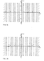
- FIGS. 3a and 3b illustrate the complex plane of the symbol constellation for a 64 QAM transmission, i.e. utilizing 64 symbols and two amplitude-modulated quadrature carriers.
- the areas indicated with broken lines are the region R. i of the plane in which the sign of the self-decided error ê n,R is equal to the sign of the real part of the true error e n,R multiplied by a transmitted symbol of which the real part a n,R is 3 while in FIG.
- the broken-line areas indicate the region R o p of the space in which the signal of the real part of the self-decided error ê n,R is equal to the sign of the real part of the reference error ⁇ n,R when n is equal for n, n example to 6.
- x indicates the complex vector or pilot vector of the input signals to the direct equalizer block 1 and s n the complex sample of the output signal from said block 1 at the instant nT when n is the nth iteration and T is the sampling time.
- the self-decision adaptation method for the tap gains of the feedforward equalization block c with decision feedback g n for the AGC gain G , and for the ⁇ n phase of the carrier n n the followinq relationships apply.
- wnere as mentioned above is the self-decided complex error and is the complex input vector with L dimensions of the decision feedback equalization block 2.
- a, y, ⁇ R and ⁇ I are real values for the adaptation steps, which can vary with each iteration n.
- the object of the invention is to identify certain intervals of the axis z n,R (or z n,I ) which favour the adaptation and exclude others. Regardless of the trans- mitted symbols a n,R appropriate selection of a region R op on on op the axis z n,R (or z n,I ) considerably increases the probability p n of equation 9 in the adaptation method based on self-decisions each time the equalizer output signal samples z n,R (or z n,I ) belong to the region R op identified. When this event occurs the adaptation proceeds but when neither z n,R nor z n,I belong to the region R op the adaptation is stopped for that iteration.
- the adaptation proceeds for the real part and is stopped for the imaginary part and vice versa.
- the adaptation proceed only when both the real part z n,R and the imaginary part z n,I of the z n signal belong simultaneously to the region R op identified.
- the maximum level error (MLE) technique uses for the adaptation only those signal samples z n,R (or z n,I ) such that z n,R
- MLE maximum level error
- ⁇ n is an appropriate real value which can vary with each iteration n.
- ⁇ n can conveniently be selected by maximizing the probability p n of equation 9 or by computer simulation.
- the purpose of the reference errors e n, R and ê n,I is only to determine the zones of the axes z and z I in which the self-decided errors ê n,R and ê n,I of the self-decided symbols â n,R and â n,I are sufficiently reliable for adap- tation.
- equations 1 to 4 are modified as follows: where f n,R and f n,I are the real and imaginary parts respectively of a complex binary consent function f which take on the following values. and narrow the field of application of the equations 1-4 to only the region R op in which the self-decided errors ê n,R and ê n,I are very reliable.
- the region R op for the axis z n,R for a 64 QAM transmission and for ⁇ n 6 is illustrated in FIG. 3b.
- the speed of convergence depends on the conditioned probability that the events of equation 17 will occur and this is given by and the method described by equations 11-14 reachs an excellent compromise between probability p that the correction when it occurs will have the right sign and probability P go that it will really occur thus producing smoothness and speed of said convergence.
- the convergence method described by equations 11-14 for each iteration comprises the following operations: (1) construction of the self-decided error e , (2) construction n of the binary consent function f , and (3) correcting of the n values of c n,R , c n,I, g nR , g n,I , G n and ⁇ n .
- the real part z n,R of the complex signal sample z n reaches the noninverting input of the adder 11 and the sign calculation block 12 while the imaginary part z n,I of said sign reaches the noninverting input of the adder 13 and the sign calculation block 14.
- the signals taken from the blocks 12 and 14 through the multipliers 15 and 16 are multiplied by a real quantity ⁇ generated by the block 17. n In particular this quantity instead of varying with each iteration could be fixed and always take on the same value S.
- the output signals of the multipliers 15 and 16 are sent respectively to the inverting inputs of the adders 11 and 13.
- the output signals of the adders 11 and 13, which represent the real part ⁇ n,R and the imaginary part ⁇ n,I respectively of the reference error ⁇ n go to the two sign calculation blocks 18 and 19.
- the real part ê n,R of the complex sample of the self-decided error ê n goes to the sign calculation block 22 and to the multiplier 23 while the imaginary part ê n,I of said error goes to the sign calculation block 24 and to the multiplier 25.
- the output signals of the blocks 22 and 24 which represent the signs of the real part ê n,R and of the imaginary part ê n,I of the complex sample of the self- decided error ê n go respectively to the multipliers 20 and 21.
- the output signal of the multiplier 20, which represents the product of the signs of the real part ê n,R of the self-decided error ê n and of the real part ⁇ n,R of the reference error e goes to the decision block 26 while the n output signal of the multiplier 21 which represents the product of the signs of the imaginary part ê n,I of the self-decided error ê n and of the imaginary part ⁇ n,I of the reference error e n goes to the decision block 27.
- the decision blocks 26 and 27 On the basis of the input signal the decision blocks 26 and 27 generate two binary functions so that when said input signal is positive there is a 1 at their outputs while when it is negative there is a 0.
- the outputs of the decision blocks 26 and 27 which represent respectively the real part f n,R and the imaginary part f n,I of the binary consent function f n go to the multipliers 23 and 25.
- the output of the multiplier 23 which is the product of the real part f n,R of the binary consent function f and of n the real part ê n,R of the self-decided error ê n and the n output of the multiplier 25 which is the product of the imaginary part f n,I of the binary consent function f n and of the imaginary part ê n,I of the self-decided error ê n go to the multiplier blocks 28, 29 and 30.
- the output signals of the multiplier block 28 which are present or not depending on the value of the binary consent function f , go to the amplifier block 31 n which amplifies a times all the samples present at its input.
- the N complex samples thus amplified go to the inverting input of the adder block 32, to the noninverting input of which also arrive the N amplified complex samples of the previous iteration which were memorized in the memory block 33.
- the output signals of the adder block 32 which represent the difference between the N present samples and the N samples of the previous iteration go to update the values of the tap gains c of the feedforward equalization block 1.
- the output signal of the multiplier block 30 which is also present or not depending on the value of the binary consent function f n goes to the separation block of the real part 35 and to the separation block of the imaginary part 36.
- the output of the block 35 goes to the amplifier 37 which amplifiesl ⁇ R times the signal present at its input.
- the amplified signal then through a circuit similar to that illustrated above for the input signal x which is not illustrated in the figures goes to update the value of the gain G n of the automatic gain control block 6.
- the output of the block 36 goes to the amplifier 38 which amplifies ⁇ l times the signal present at its input.
- the amplifed signal then goes to update the value of the phase $ of the local oscillator VCO n of the block 7.
- the values of the tap gains c Rand c n,I of the feedforward equalization block 1 and of the tap gains g n,R and g n , I of the decision feedback equalization block 2 are adjusted until they reach their optimal value.
- the convergence method described uses the self-decided symbols â n so that once adaptation is obtained there are the optimal conditions for correct decision of the symbols under steady state conditions without having to pass from one method to another from the convergence phase to the steady state phase.
- the present method has been described for a synchronous transmission of the signals, i.e. in which the sampling time and the delay introduced by each of the delay lines of the feedforward equalization blocks 1 and decision feedback blocks 2 are equal to the symbol transmission time T, but it is perfectly applicable with no significant change as well to a so-called fractionary equalization system, i.e. in which the delay introduced by each delay line in the feedforward equalization block and hence the sampling time at the receiver is smaller than the symbol transmission time T, e.g. half.
- the method is also fully applicable to an equalization system in which a single equalization block is used and in which it is not desired to recover the carrier phase, i.e. in which the block 1 or 2 and the blocks 6 and 7 might be missing.
Landscapes
- Engineering & Computer Science (AREA)
- Power Engineering (AREA)
- Computer Networks & Wireless Communication (AREA)
- Signal Processing (AREA)
- Cable Transmission Systems, Equalization Of Radio And Reduction Of Echo (AREA)
- Digital Transmission Methods That Use Modulated Carrier Waves (AREA)
Applications Claiming Priority (2)
| Application Number | Priority Date | Filing Date | Title |
|---|---|---|---|
| IT1986686 | 1986-03-25 | ||
| IT19866/86A IT1188626B (it) | 1986-03-25 | 1986-03-25 | Metodo e dispositivo di equalizzazione adattiva cieca |
Publications (3)
| Publication Number | Publication Date |
|---|---|
| EP0239153A2 true EP0239153A2 (fr) | 1987-09-30 |
| EP0239153A3 EP0239153A3 (en) | 1990-03-28 |
| EP0239153B1 EP0239153B1 (fr) | 1993-09-29 |
Family
ID=11161907
Family Applications (1)
| Application Number | Title | Priority Date | Filing Date |
|---|---|---|---|
| EP87200400A Expired - Lifetime EP0239153B1 (fr) | 1986-03-25 | 1987-03-05 | Procédé et dispositif pour égalisation adaptative aveugle |
Country Status (9)
| Country | Link |
|---|---|
| US (1) | US4847797A (fr) |
| EP (1) | EP0239153B1 (fr) |
| JP (1) | JPS62232223A (fr) |
| CN (1) | CN1010733B (fr) |
| AU (1) | AU593071B2 (fr) |
| DE (1) | DE3787550T2 (fr) |
| ES (1) | ES2043644T3 (fr) |
| IT (1) | IT1188626B (fr) |
| ZA (1) | ZA872196B (fr) |
Cited By (7)
| Publication number | Priority date | Publication date | Assignee | Title |
|---|---|---|---|---|
| EP0381637A1 (fr) * | 1989-01-26 | 1990-08-08 | Telefonaktiebolaget L M Ericsson | Une méthode pour la régulation de la fréquence d'un poste de radio cohérent et dispositif pour l'opération de la méthode |
| EP0381636A1 (fr) * | 1989-01-26 | 1990-08-08 | Telefonaktiebolaget L M Ericsson | Méthode pour la régulation rapide de la fréquence d'un poste de radio cohérent et dispositif de mise en oeuvre de la méthode |
| EP0308959A3 (en) * | 1987-09-25 | 1990-10-31 | Nec Corporation | Receiver capable of improving signal-to-noise ratio in reproducing digital signals |
| GB2278762A (en) * | 1993-06-02 | 1994-12-07 | Samsung Electronics Co Ltd | Blind equalization in a digital communications receiver |
| EP0663764A1 (fr) * | 1994-01-18 | 1995-07-19 | Daewoo Electronics Co., Ltd | Dispositif d'égalisation avec un fonctionnement de mise à jour rapide des coéfficients de filtrage |
| EP0663766A1 (fr) * | 1994-01-18 | 1995-07-19 | Daewoo Electronics Co., Ltd | Dispositif d'égalisation avec un fonctionnement de mise à jour rapide des coéfficients de filtrage |
| KR19990083149A (ko) * | 1998-04-24 | 1999-11-25 | 루센트 테크놀러지스 인크 | 일정 모듈러스 알고리즘 및 다중 모듈러스 알고리즘의 연합적 사용을 갖는 맹목적 등화 알고리즘 |
Families Citing this family (24)
| Publication number | Priority date | Publication date | Assignee | Title |
|---|---|---|---|---|
| DE3852395T2 (de) * | 1988-10-17 | 1995-05-24 | Ibm | Adaptiver Entzerrer für Aufzeichnungssysteme unter Verwendung von Partial-Response-Signalisierung. |
| ATE125090T1 (de) * | 1990-03-28 | 1995-07-15 | Alcatel Nv | Verfahren zur bestimmung der koeffizienten eines fir-filters bei entzerrern. |
| FR2666947A1 (fr) * | 1990-09-18 | 1992-03-20 | Trt Telecom Radio Electr | Dispositif d'egalisation de spectre. |
| JP2551231B2 (ja) * | 1990-11-16 | 1996-11-06 | 日本電気株式会社 | 判定帰還形等化器 |
| US5347541A (en) * | 1992-11-02 | 1994-09-13 | The Regents Of The Univ. Of California | Apparatus and method for utilizing a blind equalizer based on a Bayesian symbol sequence estimator for use in digital communication |
| US5432725A (en) * | 1993-12-15 | 1995-07-11 | The United States Of America As Represented By The Secretary Of The Navy | Self-adapting filter |
| US5539774A (en) * | 1994-06-15 | 1996-07-23 | International Business Machines Corporation | Dual decision equalization method and device |
| US5526378A (en) * | 1994-12-14 | 1996-06-11 | Thomson Consumer Electronics, Inc. | Blind multipath correction for digital communication channel |
| US5559830A (en) * | 1995-01-23 | 1996-09-24 | Xetron Corp. | Equalization system for AM compatible digital receiver |
| US5703954A (en) * | 1996-02-20 | 1997-12-30 | Usa Digital Radio Partners, L.P. | Method and apparatus for improving the quality of AM compatible digital broadcast system signals in the presence of distortion |
| US5898732A (en) * | 1996-02-20 | 1999-04-27 | Usa Digital Radio Partners, L.P. | Data service channel provision for an AM compatible broadcast system |
| US5809065A (en) * | 1996-02-20 | 1998-09-15 | Usa Digital Radio Partners, L.P. | Method and apparatus for improving the quality of AM compatible digital broadcast system signals in the presence of distortion |
| EP0820173A3 (fr) * | 1996-07-16 | 2001-01-24 | Matsushita Electric Industrial Co., Ltd. | Récepteur MAQ, à compensation d'erreur en phase et en fréquence en bande de base |
| US5930687A (en) * | 1996-09-30 | 1999-07-27 | Usa Digital Radio Partners, L.P. | Apparatus and method for generating an AM-compatible digital broadcast waveform |
| US5878089A (en) * | 1997-02-21 | 1999-03-02 | Usa Digital Radio Partners, L.P. | Coherent signal detector for AM-compatible digital audio broadcast waveform recovery |
| US6128334A (en) * | 1997-02-21 | 2000-10-03 | Usa Digital Radio, Inc. | Receiver addressable AM compatible digital broadcast system |
| US7085691B2 (en) * | 1999-11-04 | 2006-08-01 | Verticalband, Limited | Reliable symbols as a means of improving the performance of information transmission systems |
| US7143013B2 (en) * | 1999-11-04 | 2006-11-28 | Verticalband, Limited | Reliable symbols as a means of improving the performance of information transmission systems |
| US7110923B2 (en) * | 1999-11-04 | 2006-09-19 | Verticalband, Limited | Fast, blind equalization techniques using reliable symbols |
| ATE327651T1 (de) * | 2001-10-22 | 2006-06-15 | Tridonicatco Gmbh & Co Kg | Fehlerkorrektur von referenzwerten in elektronischen schaltungen |
| JP2007537666A (ja) * | 2004-05-12 | 2007-12-20 | トムソン ライセンシング | イコライザエラー信号のためのコンステレーション位置依存ステップサイズ |
| US7327914B1 (en) * | 2004-08-10 | 2008-02-05 | The Board Of Trustees Of The Leland Stanford Junior University | Adaptive optical signal processing with multimode waveguides |
| US8793560B2 (en) * | 2006-03-14 | 2014-07-29 | Qualcomm Incorporated | Log-likelihood ratio (LLR) computation using piecewise linear approximation of LLR functions |
| US10972319B2 (en) * | 2018-09-12 | 2021-04-06 | Texas Instruments Incorporated | Clockless decision feedback equalization (DFE) for multi-level signals |
Family Cites Families (12)
| Publication number | Priority date | Publication date | Assignee | Title |
|---|---|---|---|---|
| US4021738A (en) * | 1976-03-01 | 1977-05-03 | Bell Telephone Laboratories, Incorporated | Adaptive equalizer with fast convergence properties |
| US4027258A (en) * | 1976-06-01 | 1977-05-31 | Xerox Corporation | Time domain automatic equalizer with frequency domain control |
| US4054273A (en) * | 1976-08-09 | 1977-10-18 | A-1 Engineering, Inc. | Dispersion apparatus for injection molding filter |
| JPS5630968A (en) * | 1979-08-22 | 1981-03-28 | Sumitomo Chem Co Ltd | Novel tricyclic cage-shaped amine derivative |
| JPS57116436A (en) * | 1981-01-12 | 1982-07-20 | Nec Corp | Demodulator |
| JPH0249580B2 (ja) * | 1981-06-29 | 1990-10-30 | Nippon Electric Co | Jidotokaki |
| US4438521A (en) * | 1982-06-07 | 1984-03-20 | Rca Corporation | Automatically adaptive transversal filter |
| IT1158646B (it) * | 1982-06-11 | 1987-02-18 | Consiglio Nazionale Ricerche | Sistema di equalizzazione adattiva auto-ortogonalizzante nel dominio delle frequenze discrete ed equalizzatore che attua il sistema |
| JPS592447A (ja) * | 1982-06-28 | 1984-01-09 | Fujitsu Ltd | 自動等化器を有するデ−タ伝送システム |
| JPS6016129A (ja) * | 1983-07-08 | 1985-01-26 | 日本電気株式会社 | 電源リセツト回路 |
| US4564952A (en) * | 1983-12-08 | 1986-01-14 | At&T Bell Laboratories | Compensation of filter symbol interference by adaptive estimation of received symbol sequences |
| AR241298A1 (es) * | 1985-10-03 | 1992-04-30 | Siemens Ag | Ecualizador transversal adaptivo . |
-
1986
- 1986-03-25 IT IT19866/86A patent/IT1188626B/it active
-
1987
- 1987-02-27 US US07/019,563 patent/US4847797A/en not_active Expired - Fee Related
- 1987-03-04 AU AU69703/87A patent/AU593071B2/en not_active Ceased
- 1987-03-05 EP EP87200400A patent/EP0239153B1/fr not_active Expired - Lifetime
- 1987-03-05 ES ES87200400T patent/ES2043644T3/es not_active Expired - Lifetime
- 1987-03-05 DE DE87200400T patent/DE3787550T2/de not_active Expired - Lifetime
- 1987-03-25 CN CN87102279A patent/CN1010733B/zh not_active Expired
- 1987-03-25 ZA ZA872196A patent/ZA872196B/xx unknown
- 1987-03-25 JP JP62069256A patent/JPS62232223A/ja active Pending
Non-Patent Citations (3)
| Title |
|---|
| CONFERENCE RECORD OF THE 19TH ASILOMAR CONFERENCE ON CIRCUITS, SYSTEMS & COMPUTERS, Pacific Grove, CA, 6th-8th November 1985, pages 107-110, IEEE, New York, US; S. TU et al.: "Two dimensional adaptive equalizer for voiceband data transmission" * |
| IEEE TRANSACTIONS ON COMMUNICATIONS, vol. COM-32, no. 8, August 1984, pages 871-883, IEEE, New York, US; A. BENVENISTE et al.: "Blind equalizers" * |
| PROCEEDINGS OF THE IEEE, vol. 73, no. 9, September 1985, pages 1349-1387, IEEE, New York, US; S.U.H. QURESHI: "Adaptive equalization" * |
Cited By (16)
| Publication number | Priority date | Publication date | Assignee | Title |
|---|---|---|---|---|
| EP0308959A3 (en) * | 1987-09-25 | 1990-10-31 | Nec Corporation | Receiver capable of improving signal-to-noise ratio in reproducing digital signals |
| US5136616A (en) * | 1989-01-26 | 1992-08-04 | Telefonaktiebolaget L. M. Ericsson | Method of rapidly controlling the frequency of a coherent radio receiver and apparatus for carrying out the method |
| EP0381637A1 (fr) * | 1989-01-26 | 1990-08-08 | Telefonaktiebolaget L M Ericsson | Une méthode pour la régulation de la fréquence d'un poste de radio cohérent et dispositif pour l'opération de la méthode |
| WO1990009070A1 (fr) * | 1989-01-26 | 1990-08-09 | Telefonaktiebolaget Lm Ericsson | Procede de regulation de la frequence d'un recepteur radio coherent et appareil de realisation dudit procede |
| EP0381636A1 (fr) * | 1989-01-26 | 1990-08-08 | Telefonaktiebolaget L M Ericsson | Méthode pour la régulation rapide de la fréquence d'un poste de radio cohérent et dispositif de mise en oeuvre de la méthode |
| AU619944B2 (en) * | 1989-01-26 | 1992-02-06 | Telefonaktiebolaget Lm Ericsson (Publ) | A method of controlling the frequency of a coherent radio receiver and apparatus for carrying out the method |
| US5093848A (en) * | 1989-01-26 | 1992-03-03 | Telefonaktiebolaget L M Ericsson | Method of controlling the frequency of a coherent radio receiver and apparatus for carrying out the method |
| WO1990009069A1 (fr) * | 1989-01-26 | 1990-08-09 | Telefonaktiebolaget Lm Ericsson | Procede de regulation rapide de la frequence d'un recepteur radio coherent et appareil de realisation dudit procede |
| AU621183B2 (en) * | 1989-01-26 | 1992-03-05 | Telefonaktiebolaget Lm Ericsson (Publ) | A method of rapidly controlling the frequency of a coherent radio receiver and apparatus for carrying out the method |
| GB2278762A (en) * | 1993-06-02 | 1994-12-07 | Samsung Electronics Co Ltd | Blind equalization in a digital communications receiver |
| GB2278762B (en) * | 1993-06-02 | 1997-11-05 | Samsung Electronics Co Ltd | Decision directed algorithm control method |
| EP0663766A1 (fr) * | 1994-01-18 | 1995-07-19 | Daewoo Electronics Co., Ltd | Dispositif d'égalisation avec un fonctionnement de mise à jour rapide des coéfficients de filtrage |
| EP0663764A1 (fr) * | 1994-01-18 | 1995-07-19 | Daewoo Electronics Co., Ltd | Dispositif d'égalisation avec un fonctionnement de mise à jour rapide des coéfficients de filtrage |
| US5491518A (en) * | 1994-01-18 | 1996-02-13 | Daewoo Electronics Co., Ltd. | Equalization apparatus with fast coefficient updating operation |
| US5502507A (en) * | 1994-01-18 | 1996-03-26 | Daewoo Electronics Co., Ltd. | Equalization apparatus with fast coefficient updating operation |
| KR19990083149A (ko) * | 1998-04-24 | 1999-11-25 | 루센트 테크놀러지스 인크 | 일정 모듈러스 알고리즘 및 다중 모듈러스 알고리즘의 연합적 사용을 갖는 맹목적 등화 알고리즘 |
Also Published As
| Publication number | Publication date |
|---|---|
| CN1010733B (zh) | 1990-12-05 |
| IT1188626B (it) | 1988-01-20 |
| IT8619866A1 (it) | 1987-09-25 |
| CN87102279A (zh) | 1987-10-07 |
| AU593071B2 (en) | 1990-02-01 |
| AU6970387A (en) | 1987-10-01 |
| JPS62232223A (ja) | 1987-10-12 |
| DE3787550T2 (de) | 1994-03-10 |
| EP0239153B1 (fr) | 1993-09-29 |
| DE3787550D1 (de) | 1993-11-04 |
| ZA872196B (en) | 1987-11-25 |
| ES2043644T3 (es) | 1994-01-01 |
| EP0239153A3 (en) | 1990-03-28 |
| US4847797A (en) | 1989-07-11 |
| IT8619866A0 (it) | 1986-03-25 |
Similar Documents
| Publication | Publication Date | Title |
|---|---|---|
| EP0239153B1 (fr) | Procédé et dispositif pour égalisation adaptative aveugle | |
| US4227152A (en) | Method and device for training an adaptive equalizer by means of an unknown data signal in a quadrature amplitude modulation transmission system | |
| US4709374A (en) | Technique for decision-directed equalizer train/retrain | |
| US4730343A (en) | Decision feedback equalizer with a pattern detector | |
| US5369668A (en) | Fast response matched filter receiver with decision feedback equalizer | |
| US4453256A (en) | Adaptive equalizer system for quadrature amplitude modulation | |
| CN108270715A (zh) | 适合高阶4096-qam的载波恢复系统和方法 | |
| US6351293B1 (en) | Decision directed phase detector | |
| GB1587421A (en) | Method of and apparatus for digital signal equalization | |
| KR100930988B1 (ko) | 위상 추적 시스템 및 방법 | |
| JP4224152B2 (ja) | シンボルタイミング回復装置及び方法 | |
| US6879630B2 (en) | Automatic equalization circuit and receiver circuit using the same | |
| JPH0879135A (ja) | デジタル信号誤り低減装置 | |
| CN120604476A (zh) | 自适应均衡电路、自适应均衡装置、接收机和自适应均衡方法 | |
| US4759036A (en) | Decision-directed control circuit | |
| EP0122637A2 (fr) | Egalisateur auto-adaptatif | |
| JP2785858B2 (ja) | 高速制御適応フィルタを用いた受信方式 | |
| JPH06500914A (ja) | 信号点、等化器利得などを調整する装置および方法 | |
| CN101567862A (zh) | 用于通信接收器中的均衡系统与执行均衡的方法 | |
| US20110063519A1 (en) | Carrier recovery device and method, and demodulator | |
| US20030169832A1 (en) | LMS-based channel estimation | |
| US7312833B2 (en) | Channel equalizing apparatus and method for digital television receiver | |
| WO2003005660A2 (fr) | Initialiseur de poids de prises pour egaliseur adaptatif | |
| JP4425520B2 (ja) | 高精細度テレビジョン信号用のブラインド等化装置 | |
| JP3865596B2 (ja) | 自動等化回路およびそれを用いた受信回路 |
Legal Events
| Date | Code | Title | Description |
|---|---|---|---|
| PUAI | Public reference made under article 153(3) epc to a published international application that has entered the european phase |
Free format text: ORIGINAL CODE: 0009012 |
|
| AK | Designated contracting states |
Kind code of ref document: A2 Designated state(s): BE DE ES FR GB GR IT NL |
|
| RAP1 | Party data changed (applicant data changed or rights of an application transferred) |
Owner name: SIEMENS TELECOMUNICAZIONI S.P.A. |
|
| PUAL | Search report despatched |
Free format text: ORIGINAL CODE: 0009013 |
|
| AK | Designated contracting states |
Kind code of ref document: A3 Designated state(s): BE DE ES FR GB GR IT NL |
|
| 17P | Request for examination filed |
Effective date: 19900917 |
|
| 17Q | First examination report despatched |
Effective date: 19920402 |
|
| GRAA | (expected) grant |
Free format text: ORIGINAL CODE: 0009210 |
|
| ITF | It: translation for a ep patent filed | ||
| AK | Designated contracting states |
Kind code of ref document: B1 Designated state(s): BE DE ES FR GB GR IT NL |
|
| REF | Corresponds to: |
Ref document number: 3787550 Country of ref document: DE Date of ref document: 19931104 |
|
| ET | Fr: translation filed | ||
| REG | Reference to a national code |
Ref country code: ES Ref legal event code: FG2A Ref document number: 2043644 Country of ref document: ES Kind code of ref document: T3 |
|
| REG | Reference to a national code |
Ref country code: GR Ref legal event code: FG4A Free format text: 3009926 |
|
| ITF | It: translation for a ep patent filed | ||
| PLBE | No opposition filed within time limit |
Free format text: ORIGINAL CODE: 0009261 |
|
| STAA | Information on the status of an ep patent application or granted ep patent |
Free format text: STATUS: NO OPPOSITION FILED WITHIN TIME LIMIT |
|
| 26N | No opposition filed | ||
| PGFP | Annual fee paid to national office [announced via postgrant information from national office to epo] |
Ref country code: GB Payment date: 19970224 Year of fee payment: 11 |
|
| PGFP | Annual fee paid to national office [announced via postgrant information from national office to epo] |
Ref country code: ES Payment date: 19970312 Year of fee payment: 11 |
|
| PGFP | Annual fee paid to national office [announced via postgrant information from national office to epo] |
Ref country code: GR Payment date: 19970314 Year of fee payment: 11 |
|
| PGFP | Annual fee paid to national office [announced via postgrant information from national office to epo] |
Ref country code: BE Payment date: 19970317 Year of fee payment: 11 |
|
| PGFP | Annual fee paid to national office [announced via postgrant information from national office to epo] |
Ref country code: NL Payment date: 19970320 Year of fee payment: 11 |
|
| PG25 | Lapsed in a contracting state [announced via postgrant information from national office to epo] |
Ref country code: GB Free format text: LAPSE BECAUSE OF NON-PAYMENT OF DUE FEES Effective date: 19980305 |
|
| PG25 | Lapsed in a contracting state [announced via postgrant information from national office to epo] |
Ref country code: ES Free format text: LAPSE BECAUSE OF EXPIRATION OF PROTECTION Effective date: 19980306 |
|
| PG25 | Lapsed in a contracting state [announced via postgrant information from national office to epo] |
Ref country code: GR Free format text: LAPSE BECAUSE OF NON-PAYMENT OF DUE FEES Effective date: 19980331 Ref country code: BE Free format text: LAPSE BECAUSE OF NON-PAYMENT OF DUE FEES Effective date: 19980331 |
|
| BERE | Be: lapsed |
Owner name: SIEMENS TELECOMUNICAZIONI S.P.A. Effective date: 19980331 |
|
| PG25 | Lapsed in a contracting state [announced via postgrant information from national office to epo] |
Ref country code: NL Free format text: LAPSE BECAUSE OF NON-PAYMENT OF DUE FEES Effective date: 19981001 |
|
| GBPC | Gb: european patent ceased through non-payment of renewal fee |
Effective date: 19980305 |
|
| NLV4 | Nl: lapsed or anulled due to non-payment of the annual fee |
Effective date: 19981001 |
|
| REG | Reference to a national code |
Ref country code: ES Ref legal event code: FD2A Effective date: 20000301 |
|
| PGFP | Annual fee paid to national office [announced via postgrant information from national office to epo] |
Ref country code: FR Payment date: 20060324 Year of fee payment: 20 |
|
| PGFP | Annual fee paid to national office [announced via postgrant information from national office to epo] |
Ref country code: IT Payment date: 20060331 Year of fee payment: 20 |
|
| PGFP | Annual fee paid to national office [announced via postgrant information from national office to epo] |
Ref country code: DE Payment date: 20060522 Year of fee payment: 20 |