EP0239678A1 - Procédé et appareil pour déterminer et localiser des surchauffes locales dans des enroulements à bain de refroidissement des machines électriques - Google Patents
Procédé et appareil pour déterminer et localiser des surchauffes locales dans des enroulements à bain de refroidissement des machines électriques Download PDFInfo
- Publication number
- EP0239678A1 EP0239678A1 EP86117807A EP86117807A EP0239678A1 EP 0239678 A1 EP0239678 A1 EP 0239678A1 EP 86117807 A EP86117807 A EP 86117807A EP 86117807 A EP86117807 A EP 86117807A EP 0239678 A1 EP0239678 A1 EP 0239678A1
- Authority
- EP
- European Patent Office
- Prior art keywords
- sound
- bubble
- noises
- liquid
- cooled
- Prior art date
- Legal status (The legal status is an assumption and is not a legal conclusion. Google has not performed a legal analysis and makes no representation as to the accuracy of the status listed.)
- Granted
Links
- 238000004804 winding Methods 0.000 title claims abstract description 25
- 238000000034 method Methods 0.000 title claims abstract description 20
- 238000013021 overheating Methods 0.000 title claims abstract description 11
- 230000004807 localization Effects 0.000 title description 3
- 238000001514 detection method Methods 0.000 title description 2
- 239000002826 coolant Substances 0.000 claims abstract description 10
- 238000012544 monitoring process Methods 0.000 claims description 7
- 239000000110 cooling liquid Substances 0.000 claims description 6
- 238000011156 evaluation Methods 0.000 claims description 6
- 230000005236 sound signal Effects 0.000 claims description 4
- 238000005259 measurement Methods 0.000 claims description 2
- 238000009835 boiling Methods 0.000 claims 1
- XLYOFNOQVPJJNP-UHFFFAOYSA-N water Substances O XLYOFNOQVPJJNP-UHFFFAOYSA-N 0.000 abstract description 8
- 230000002950 deficient Effects 0.000 abstract description 2
- 238000001816 cooling Methods 0.000 description 5
- 239000007788 liquid Substances 0.000 description 4
- 239000004020 conductor Substances 0.000 description 3
- 230000035945 sensitivity Effects 0.000 description 2
- 241001598984 Bromius obscurus Species 0.000 description 1
- 239000007789 gas Substances 0.000 description 1
- 239000011810 insulating material Substances 0.000 description 1
- 239000002245 particle Substances 0.000 description 1
- 238000012545 processing Methods 0.000 description 1
- 230000001902 propagating effect Effects 0.000 description 1
- 230000002123 temporal effect Effects 0.000 description 1
Images

Classifications
-
- G—PHYSICS
- G01—MEASURING; TESTING
- G01R—MEASURING ELECTRIC VARIABLES; MEASURING MAGNETIC VARIABLES
- G01R31/00—Arrangements for testing electric properties; Arrangements for locating electric faults; Arrangements for electrical testing characterised by what is being tested not provided for elsewhere
- G01R31/34—Testing dynamo-electric machines
-
- H—ELECTRICITY
- H02—GENERATION; CONVERSION OR DISTRIBUTION OF ELECTRIC POWER
- H02K—DYNAMO-ELECTRIC MACHINES
- H02K9/00—Arrangements for cooling or ventilating
- H02K9/24—Protection against failure of cooling arrangements, e.g. due to loss of cooling medium or due to interruption of the circulation of cooling medium
Definitions
- the present invention relates to a method for determining local overheating in liquid-cooled windings of electrical machines and a device for carrying out the method.
- Local overheating of coolant-cooled windings can be caused in particular by blockage or partial blockage of partial conductors of the winding.
- the coolant in most cases water, can then no longer dissipate the heat generated in this area, causing it to overheat, which can lead to serious consequential damage.
- thermometer to control the winding temperature or to attach liquid-cooled windings thermocouples to the earth ends of the coolant connections of the individual conductors and monitor the temperatures there. Both methods are relatively complex and their sensitivity is not particularly large, since at z. B. only a clogged partial conductor, the local temperature change is initially hardly noticeable to the outside.
- Another monitoring method is the use of a so-called generator condition monitor, which displays the gases and particles that come from overheated insulating materials.
- generator condition monitor displays the gases and particles that come from overheated insulating materials.
- this notification is usually too late, since the damage lasts until speaking this monitoring method must be well advanced. With this method, it is also not possible to locate the damaged area safely.
- the object of the present invention is to provide a method which enables rapid detection of local overheating in liquid-cooled windings and, if appropriate, also allows the location of the damage to be located. Furthermore, the simplest possible device for carrying out the method is to be specified.
- the invention is based on the finding that, in the event of local overheating, the cooling liquid, in general water, is heated up to the boil at the point of damage, as a result of which bubbles form which dissolve in cooler places. These bubbles cause characteristic noises, which propagate in the liquid and possibly also in the structure forming the cooling circuit.
- the cooling liquid is monitored acoustically by means of one or more sound pickups, which means that the bubble noises can be determined immediately in the event of damage.
- this method additionally offers the possibility of a very precise localization of the damage location.
- the sound recorders can either be arranged directly in the cooling liquid, or there is the possibility of recording the noise through the structure of the cooling circuit. In the latter case, it may be necessary to distinguish between the sound waves conducted through the structure and the sound waves transmitted through the liquid, but this does not pose any fundamental difficulties.
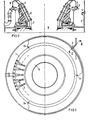
- Fig. 1 shows a highly simplified representation of an end view of the stator winding of a generator with the parts important for understanding the invention.
- Fig. 2 shows the associated longitudinal section along the line II-II in Fig. 1 through this end region of the generator.
- a coolant in the present case water, can flow through the stator winding bars 7 of the generator stand. This coolant passes from a first water collection ring 1 via hose connections 6 into the stator winding rods 7 and after exiting from the stator winding rods 7 again via hose connections 6 to a second water collection ring 1, from where it is returned to the circuit.
- the ends of the stator winding bars 7 lie between the winding head cover plates 8 and may have switching connections 5.
- one or both of the water collecting rings on the exit and entry side is equipped with acoustic sound recorders 2a, 2b, 2c at at least three locations, preferably each at the same distance from one another.
- These sound recorders are e.g. B. designed as a hydrophone or other sound pressure transducer and acoustically coupled to the liquid so that the sound waves propagating in the liquid can be converted into electrical signals. These signals are passed via electrical lines 3 through a hydrogen-tight bushing 4 to an electronic evaluation system.
- Each signal of each sound sensor 2a, 2b, 2c is first amplified in an amplifier 11 and then freed from disturbing background noise in a bandpass filter 12. If bubble noises occur which can pass the bandpass filter 12, these are further amplified 13 and sent to a display or warning device 14, e.g. B. forwarded in a control room. Simultaneously, the propagation time differences can ⁇ t 4 between the registered for the individual acoustic sensors signals in an analysis device 15 can be determined. In the simplest case, this device works like a stopwatch, ie it is started by the first incoming bubble noise and stopped again when the bubble noise arrives from the second or third sound pickup.
- the temporal correlation between the signals arriving from the individual sound recorders can also be formed.
- the defective winding rod from which the noise originates can be determined immediately from the resulting transit time differences. It is always in the sector between the two transducers where the signal arrived first, the transit time difference between these two transducers and their sign in connection with the speed of sound immediately allowing an exact localization. If the transit time differences to the third sound pickup are included, it is not even necessary to know the speed of sound, since this results immediately from the known distance between the sound pickups and the additionally measured travel time difference. The information about the location of the damage can then be output, for example, via a monitor 16.
- Fig. 4 shows to illustrate the sensitivity of the measuring method recorded by a recorder Sound signals from the cooling system of a generator winding, recorded with a hydrophone on the water collection ring .. -
- the signal voltage U is plotted against time t.
- the lower curve 41 shows the zero level of the undisturbed operating noise in the frequency band from approximately 200 Hz to 300 Hz.
- the upper curve 42 shows the sound level when bubbles occur in the same frequency band. A distinction of the bubble noise from the zero level in this frequency range is accordingly very precise and quick, which makes the monitoring very sensitive.
Landscapes
- Physics & Mathematics (AREA)
- General Physics & Mathematics (AREA)
- Engineering & Computer Science (AREA)
- Power Engineering (AREA)
- Motor Or Generator Cooling System (AREA)
- Measurement Of Mechanical Vibrations Or Ultrasonic Waves (AREA)
Applications Claiming Priority (2)
| Application Number | Priority Date | Filing Date | Title |
|---|---|---|---|
| DE19863600421 DE3600421A1 (de) | 1986-01-09 | 1986-01-09 | Verfahren und vorrichtung zur feststellung und ortung von lokalen uebererwaermungen in fluessigkeits-gekuehlten wicklungen elektrischer maschinen |
| DE3600421 | 1986-01-09 |
Publications (2)
| Publication Number | Publication Date |
|---|---|
| EP0239678A1 true EP0239678A1 (fr) | 1987-10-07 |
| EP0239678B1 EP0239678B1 (fr) | 1991-03-13 |
Family
ID=6291569
Family Applications (1)
| Application Number | Title | Priority Date | Filing Date |
|---|---|---|---|
| EP86117807A Expired - Lifetime EP0239678B1 (fr) | 1986-01-09 | 1986-12-19 | Procédé et appareil pour déterminer et localiser des surchauffes locales dans des enroulements à bain de refroidissement des machines électriques |
Country Status (5)
| Country | Link |
|---|---|
| US (1) | US4808867A (fr) |
| EP (1) | EP0239678B1 (fr) |
| JP (1) | JPS62221840A (fr) |
| DE (2) | DE3600421A1 (fr) |
| IN (1) | IN166031B (fr) |
Cited By (1)
| Publication number | Priority date | Publication date | Assignee | Title |
|---|---|---|---|---|
| FR3115417A1 (fr) * | 2020-10-21 | 2022-04-22 | Valeo Equipements Electriques Moteur | Machine électrique tournante refroidie et procédé de contrôle d’une telle machine tournante |
Families Citing this family (4)
| Publication number | Priority date | Publication date | Assignee | Title |
|---|---|---|---|---|
| US5074672A (en) * | 1990-10-26 | 1991-12-24 | Westinghouse Electric Corp. | Arrangement for monitoring temperatures of water-cooled electric generator windings |
| US8129873B2 (en) | 2010-04-05 | 2012-03-06 | General Electronic Company | Stator coil coolant flow reduction monitoring |
| DE102012213029A1 (de) * | 2012-07-25 | 2014-01-30 | Siemens Aktiengesellschaft | Verfahren zur Ermittlung einer Blasengrößenverteilung und Messeinrichtung |
| US10840782B2 (en) | 2017-07-12 | 2020-11-17 | Siemens Energy, Inc. | Assembly and method for connecting ends of generator stator coils with manifold |
Citations (3)
| Publication number | Priority date | Publication date | Assignee | Title |
|---|---|---|---|---|
| CH327462A (de) * | 1954-01-14 | 1958-01-31 | Siemens Ag | Uberwachungseinrichtung für die Strömung von Kühlflüssigkeit in Geräten und Maschinen |
| CH573184A5 (en) * | 1974-07-02 | 1976-02-27 | Bbc Brown Boveri & Cie | Cooling of turbogenerator rotor winding - cold water is added to hot water channels to prevent air bubbles |
| EP0080640A1 (fr) * | 1981-11-30 | 1983-06-08 | INTERATOM Gesellschaft mit beschränkter Haftung | Procédé et appareil pour détecter des bulles dans une fluide |
Family Cites Families (4)
| Publication number | Priority date | Publication date | Assignee | Title |
|---|---|---|---|---|
| US2518518A (en) * | 1946-11-06 | 1950-08-15 | Bbc Brown Boveri & Cie | Apparatus for testing electrical windings in an insulating liquid |
| US3626282A (en) * | 1970-03-02 | 1971-12-07 | Bell Telephone Labor Inc | Method for locating shunt faults in a cable utilizing the fault as a noise source |
| US3755702A (en) * | 1972-07-31 | 1973-08-28 | Gen Electric | Flow surge equipment for dynamoelectric machine |
| US4466746A (en) * | 1981-12-01 | 1984-08-21 | Robert D. Hancock | Ebulliometric hot spot detector |
-
1986
- 1986-01-09 DE DE19863600421 patent/DE3600421A1/de not_active Withdrawn
- 1986-12-19 DE DE8686117807T patent/DE3678161D1/de not_active Expired - Lifetime
- 1986-12-19 EP EP86117807A patent/EP0239678B1/fr not_active Expired - Lifetime
-
1987
- 1987-01-05 JP JP62000349A patent/JPS62221840A/ja active Pending
- 1987-01-08 US US07/001,344 patent/US4808867A/en not_active Expired - Fee Related
- 1987-01-12 IN IN35/CAL/87A patent/IN166031B/en unknown
Patent Citations (3)
| Publication number | Priority date | Publication date | Assignee | Title |
|---|---|---|---|---|
| CH327462A (de) * | 1954-01-14 | 1958-01-31 | Siemens Ag | Uberwachungseinrichtung für die Strömung von Kühlflüssigkeit in Geräten und Maschinen |
| CH573184A5 (en) * | 1974-07-02 | 1976-02-27 | Bbc Brown Boveri & Cie | Cooling of turbogenerator rotor winding - cold water is added to hot water channels to prevent air bubbles |
| EP0080640A1 (fr) * | 1981-11-30 | 1983-06-08 | INTERATOM Gesellschaft mit beschränkter Haftung | Procédé et appareil pour détecter des bulles dans une fluide |
Cited By (2)
| Publication number | Priority date | Publication date | Assignee | Title |
|---|---|---|---|---|
| FR3115417A1 (fr) * | 2020-10-21 | 2022-04-22 | Valeo Equipements Electriques Moteur | Machine électrique tournante refroidie et procédé de contrôle d’une telle machine tournante |
| WO2022084481A1 (fr) * | 2020-10-21 | 2022-04-28 | Valeo Equipements Electriques Moteur | Machine électrique tournante refroidie et procédé de contrôle d'une telle machine tournante |
Also Published As
| Publication number | Publication date |
|---|---|
| DE3678161D1 (de) | 1991-04-18 |
| IN166031B (fr) | 1990-03-03 |
| EP0239678B1 (fr) | 1991-03-13 |
| JPS62221840A (ja) | 1987-09-29 |
| US4808867A (en) | 1989-02-28 |
| DE3600421A1 (de) | 1987-07-16 |
Similar Documents
| Publication | Publication Date | Title |
|---|---|---|
| DE19507826C2 (de) | Vorrichtung zum Feststellen von Störungen oder Schäden einer elektrischen Einrichtung oder einer rotierenden elektrischen Maschine | |
| DE68907961T2 (de) | Störungserkennungssystem für elektrische Versorgungseinrichtungen. | |
| EP0045942B1 (fr) | Dispositif de détection d'usure d'outils | |
| DE2709569A1 (de) | Zentrifuge mit einer einrichtung zum aufspueren und anzeigen von torsionsschwingungen | |
| DE2738793A1 (de) | Verfahren und vorrichtung zum feststellen der bei beschaedigung eines objektes, insbesondere einer glasscheibe, auftretenden schwingungen | |
| DE2515868C3 (de) | Vorrichtung zur Messung des Blutdrucks | |
| DE2403227A1 (de) | On-line-monitor zum messen der aufprallenergie | |
| DE3111819C2 (fr) | ||
| EP0239678B1 (fr) | Procédé et appareil pour déterminer et localiser des surchauffes locales dans des enroulements à bain de refroidissement des machines électriques | |
| EP0662220B1 (fr) | Decouplage d'un signal d'erreur haute frequence d'un champ electromagnetique haute frequence dans une machine electrique de grande dimension | |
| DE2025693A1 (de) | Verfahren zur Überwachung des Betriebszustandes von Wälzlagern | |
| DE29611558U1 (de) | Vorrichtung zur Erfassung von analogen Meßsignalen für die akustische Diagnose von Prüflingen | |
| DE2650665B2 (de) | Verfahren und Vorrichtung zur Ermittlung der abgelaufenen Spielzeit bzw. Bandlänge und/oder der Restlaufzeit von Kassetten oder Spulen bandförmiger Informationsträger | |
| DE69132555T2 (de) | Verfahren und gerät zur detektion von digitalen trägersignalen auf telefonkabeln | |
| DE2440915B2 (de) | Wirbelstrompruefgeraet | |
| DE19736316A1 (de) | Vorrichtung und Verfahren zur Drehzahlüberwachung für einen Anodenantrieb von einer Röntgenröhre | |
| DE3814877A1 (de) | Signaldetektorgeraet | |
| DE3036164C2 (de) | Längenmeßeinrichtung | |
| DE3013611A1 (de) | Verfahren und vorrichtung zum identifizieren von muenzen o.dgl. | |
| DE60305204T2 (de) | Verfahren und vorrichtung zur lokalisierung einer entladung in einem stator einer elektrischen maschine | |
| DE102008052983A1 (de) | Wirbelstromsensor und Verfahren zum Ermitteln von aufgrund thermischer Einflüsse veränderter Werkstoffeigenschaften in einem zu untersuchenden Bauteil mit Hilfe desselben | |
| DE3040799C2 (de) | Verfahren zum Auswuchten von Läufern elektrischer Maschinen | |
| DE69108073T2 (de) | Verfahren und Gerät zur elektrischen Signalverarbeitung und Spannungswellenfühler. | |
| DE69212735T2 (de) | Kontrolle einer beheizten Scheibe | |
| DE2737812B2 (de) | Verfahren zur Frequenz-Analyse von transienten (einmaligen) Schallsignalen |
Legal Events
| Date | Code | Title | Description |
|---|---|---|---|
| PUAI | Public reference made under article 153(3) epc to a published international application that has entered the european phase |
Free format text: ORIGINAL CODE: 0009012 |
|
| AK | Designated contracting states |
Kind code of ref document: A1 Designated state(s): CH DE FR GB LI |
|
| 17P | Request for examination filed |
Effective date: 19871027 |
|
| 17Q | First examination report despatched |
Effective date: 19900228 |
|
| GRAA | (expected) grant |
Free format text: ORIGINAL CODE: 0009210 |
|
| AK | Designated contracting states |
Kind code of ref document: B1 Designated state(s): CH DE FR GB LI |
|
| REF | Corresponds to: |
Ref document number: 3678161 Country of ref document: DE Date of ref document: 19910418 |
|
| ET | Fr: translation filed | ||
| GBT | Gb: translation of ep patent filed (gb section 77(6)(a)/1977) | ||
| PGFP | Annual fee paid to national office [announced via postgrant information from national office to epo] |
Ref country code: GB Payment date: 19911120 Year of fee payment: 6 |
|
| PGFP | Annual fee paid to national office [announced via postgrant information from national office to epo] |
Ref country code: FR Payment date: 19911217 Year of fee payment: 6 |
|
| PLBE | No opposition filed within time limit |
Free format text: ORIGINAL CODE: 0009261 |
|
| STAA | Information on the status of an ep patent application or granted ep patent |
Free format text: STATUS: NO OPPOSITION FILED WITHIN TIME LIMIT |
|
| PGFP | Annual fee paid to national office [announced via postgrant information from national office to epo] |
Ref country code: DE Payment date: 19920225 Year of fee payment: 6 |
|
| 26N | No opposition filed | ||
| PGFP | Annual fee paid to national office [announced via postgrant information from national office to epo] |
Ref country code: CH Payment date: 19920324 Year of fee payment: 6 |
|
| PG25 | Lapsed in a contracting state [announced via postgrant information from national office to epo] |
Ref country code: GB Effective date: 19921219 |
|
| PG25 | Lapsed in a contracting state [announced via postgrant information from national office to epo] |
Ref country code: LI Effective date: 19921231 Ref country code: CH Effective date: 19921231 |
|
| GBPC | Gb: european patent ceased through non-payment of renewal fee |
Effective date: 19921219 |
|
| PG25 | Lapsed in a contracting state [announced via postgrant information from national office to epo] |
Ref country code: FR Effective date: 19930831 |
|
| REG | Reference to a national code |
Ref country code: CH Ref legal event code: PL |
|
| PG25 | Lapsed in a contracting state [announced via postgrant information from national office to epo] |
Ref country code: DE Effective date: 19930901 |
|
| REG | Reference to a national code |
Ref country code: FR Ref legal event code: ST |