EP0240360B1 - Ultraschalloszillator - Google Patents
Ultraschalloszillator Download PDFInfo
- Publication number
- EP0240360B1 EP0240360B1 EP87302925A EP87302925A EP0240360B1 EP 0240360 B1 EP0240360 B1 EP 0240360B1 EP 87302925 A EP87302925 A EP 87302925A EP 87302925 A EP87302925 A EP 87302925A EP 0240360 B1 EP0240360 B1 EP 0240360B1
- Authority
- EP
- European Patent Office
- Prior art keywords
- ultrasonic
- circuit
- feedback
- oscillator
- ultrasonic vibrator
- Prior art date
- Legal status (The legal status is an assumption and is not a legal conclusion. Google has not performed a legal analysis and makes no representation as to the accuracy of the status listed.)
- Expired - Lifetime
Links
Images
Classifications
-
- H—ELECTRICITY
- H03—ELECTRONIC CIRCUITRY
- H03B—GENERATION OF OSCILLATIONS, DIRECTLY OR BY FREQUENCY-CHANGING, BY CIRCUITS EMPLOYING ACTIVE ELEMENTS WHICH OPERATE IN A NON-SWITCHING MANNER; GENERATION OF NOISE BY SUCH CIRCUITS
- H03B5/00—Generation of oscillations using amplifier with regenerative feedback from output to input
- H03B5/08—Generation of oscillations using amplifier with regenerative feedback from output to input with frequency-determining element comprising lumped inductance and capacitance
- H03B5/12—Generation of oscillations using amplifier with regenerative feedback from output to input with frequency-determining element comprising lumped inductance and capacitance active element in amplifier being semiconductor device
-
- B—PERFORMING OPERATIONS; TRANSPORTING
- B06—GENERATING OR TRANSMITTING MECHANICAL VIBRATIONS IN GENERAL
- B06B—METHODS OR APPARATUS FOR GENERATING OR TRANSMITTING MECHANICAL VIBRATIONS OF INFRASONIC, SONIC, OR ULTRASONIC FREQUENCY, e.g. FOR PERFORMING MECHANICAL WORK IN GENERAL
- B06B1/00—Methods or apparatus for generating mechanical vibrations of infrasonic, sonic, or ultrasonic frequency
- B06B1/02—Methods or apparatus for generating mechanical vibrations of infrasonic, sonic, or ultrasonic frequency making use of electrical energy
- B06B1/0207—Driving circuits
- B06B1/0223—Driving circuits for generating signals continuous in time
- B06B1/0238—Driving circuits for generating signals continuous in time of a single frequency, e.g. a sine-wave
- B06B1/0246—Driving circuits for generating signals continuous in time of a single frequency, e.g. a sine-wave with a feedback signal
- B06B1/0253—Driving circuits for generating signals continuous in time of a single frequency, e.g. a sine-wave with a feedback signal taken directly from the generator circuit
-
- B—PERFORMING OPERATIONS; TRANSPORTING
- B06—GENERATING OR TRANSMITTING MECHANICAL VIBRATIONS IN GENERAL
- B06B—METHODS OR APPARATUS FOR GENERATING OR TRANSMITTING MECHANICAL VIBRATIONS OF INFRASONIC, SONIC, OR ULTRASONIC FREQUENCY, e.g. FOR PERFORMING MECHANICAL WORK IN GENERAL
- B06B2201/00—Indexing scheme associated with B06B1/0207 for details covered by B06B1/0207 but not provided for in any of its subgroups
- B06B2201/70—Specific application
- B06B2201/77—Atomizers
Definitions
- This invention relates generally to an ultrasonic oscillator, and particularly to an ultrasonic oscillator suitable for use in various ultrasonic atomizers, for example, fuel injection devices for automobiles.
- Ultrasonic oscillators of this character are generally so constructed as to operate safely at a constant speed. They are roughly classified into two types; the load resistor type in which a resistor is connected in series with an ultrasonic vibrator that works as an electroacoustic transducer to drive an ultrasonic vibrator horn provided in an ultrasonic atomizer, and the feedback resistor type in which a resistor is connected in series with a feedback circuit of an amplifier circuit which constitutes the ultrasonic oscillator.
- FIG. 3 illustrates a typical circuit structure of an ultrasonic oscillator of the load resistor type.
- the oscillator comprises an amplifier circuit 1; a matching coil 2 and a load resistor R27 connected to the output of the amplifier circuit 1, a balanced bridge circuit having capacitors 3, 4, and 5 and a damped capacity R1 of an ultrasonic vibrator 6 and connected to said matching coil 2 and said load resistor R27; a feedback circuit which comprises a capacitor 8 and a coil 9 connected in series, and which positively feeds an output signal of the balanced bridge circuit back to the input of the amplifier circuit 1; and an input resistor R310 connected to the input of the amplifier circuit 1.
- FIG. 4 illustrates a typical circuit of an ultrasonic oscillator of the feedback resistor type. Comparison of FIG. 4 with FIG. 3 reveals that the circuit of the ultrasonic oscillator of the feedback resistor type is generally the same as that of the load resistor type. The exception is that the feedback resistor type does not have the load resistor R2 7 employed in the load resistor type; instead, it has a feedback resistor R4 17 connected in series with the capacitor 8 and coil 9 in the feedback circuit.
- the ultrasonic oscillator of the load resistor type has disadvantages. Because the electric current (i.e., vibrator current) of the ultrasonic vibrator 6 flows directly into the load resistor R2 7 via the capacitor 5, the power loss at the load resistor R2 7 (i.e., the magnitude of electric power wastefully consumed by the resistor) reduces the efficiency of the oscillator and makes it increasingly difficult to drive the ultrasonic vibrator 6 at a constant speed as the load on the vibrator increases.
- Such disadvantages common to the ultrasonic oscillators of the load resistor type have been experimentally confirmed by the present inventors.
- FIG. 5 shows data measured by the present inventors.
- the ordinate represents the ratio of the vibration velocity v to the vibration velocity v0 under the no-load condition of the vibrator 6.
- the abscissa represents the ratio of the equivalent series resistance R1 of the ultrasonic vibrator 6 to the input resistance R3 10.
- Curves 11, 12, 13, 14, 15, and 16 represent the vibration velocity characteristics of the ultrasonic vibrator 6 using the ratios of the load resistance R2 7 to the input resistance R3 10 as parameters.
- the ultrasonic vibrator 6 begins to work outside the constant-speed operation range as the values of the load resistance R2 7 and the equivalent series resistance R1 of the ultrasonic vibrator 6 increase, and that the ultrasonic vibrator 6 operates at a constant speed independently of the equivalent series resistance R1 only when the load resistance R2 7 is zero.
- the data imply that, in addition to the aforementioned defects, the ultrasonic oscillator of the load resistor type has a disadvantage of a low upper limit to the load with which the oscillator can continue the oscillation without coming to a halt (or stall).
- the oscillatable frequency band width of the amplifier circuit 1 in the steady-state condition is narrower than the resonance frequency band width of the ultrasonic vibrator 6 that varies with changes in the temperature and in the load.
- a substantial limitation is thus imposed on changing the oscillation frequency according to changes in the resonance frequency of the ultrasonic vibrator 6.
- transistors and other semiconductor amplifier elements are damaged by an over-excited input to the amplifier circuit 1.
- the ultrasonic oscillator of the load resistor type has so many disadvantages that it is far from being of practical use.
- the ultrasonic oscillator of the feedback resistor type may be said to be more trouble-free since it dispenses with the load resistor R2 7 that presents the above-mentioned disadvantages.
- the present inventors have found that the feedback resistor type too has problems as described below.
- the gain ⁇ of the circuit system is much greater than 1, the characteristics of the ultrasonic vibrator 6 at the start of oscillation, i.e., during the rise, and the upper limit of the load with which the oscillator continues the oscillation without stall is high.
- the circuit system further features improved constant-speed operation performance and improved efficiency common to the devices of the feedback resistor type.
- the frequency band width of the amplifier circuit 1 is so narrow that it cannot follow the vibrations in resonance frequency of the ultrasonic vibrator 6 with changes in the temperature and in the load, and semiconductor amplifier elements such as transistors can be broken down due to an over-excited input to the amplifier circuit 1.
- the amplifier circuit 1 has a broad oscillatable frequency band width, and there is no possibility of the semiconductor amplifier elements such as transistors being broken down by an over-excited input to the amplifier circuit 1.
- the oscillator features the afore-mentioned advantages common to the feedback resistor type.
- the feedback input voltage to the amplifier circuit 1 is divided by the feedback resistor R4 17 having a large resistance, the circuit system seldom produces a gain ⁇ » 1.
- the ultrasonic vibrator 6 starts to oscillate only when it is practically under no load, and the oscillator has a low upper limit of load with which it continues the oscillation without coming to a stall.
- the present invention has now been made to settle the afore-described problems of the prior art. Its object is to provide an ultrasonic oscillator which exhibits excellent characteristics both when the feedback resistance is substantially smaller, and when it is substantially larger, than the input resistance of the amplifier circuit.
- an ultrasonic oscillator which comprises: an ultrasonic vibrator for driving an ultrasonic vibrator horn of an ultrasonic atomizer; a bridge circuit in which the ultrasonic vibrator and capacitor elements are connected so that a balanced condition is established with respect to the damped capacity of the ultrasonic vibrator; and amplifier means for sending a signal to the bridge circuit and which includes a feedback circuit for positively feeding back the signal output from the bridge circuit; said feedback circuit having means connected thereto for adjusting the feedback quantity so that, when the ultrasonic oscillator starts the oscillation, the signal feedback quantity output from the bridge circuit is adjusted to make the gain of the amplifier means much greater than 1, and when the oscillator is in the steadily oscillating condition, the signal feedback quantity output from the bridge circuit is adjusted to broaden the allowable frequency band width of the ultrasonic vibrator.
- the dependent claims show particular embodiments of the invention.
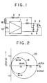
- FIG. 1 is a diagram illustrating the circuit of an ultrasonic oscillator of the feedback resistor type embodying the present invention, similar to that of the feedback resistor type shown in FIG. 4.
- the ultrasonic oscillator of the feedback resistor type embodying the invention comprises an amplifier circuit 1; a balanced bridge circuit which consists of inductance elements, i.e., capacitor elements or capacitors 3, 4, and 5 connected to a matching coil 2 connected to the output of the amplifier circuit 1, and a damped capacity of an ultrasonic vibrator 6; a feedback circuit which consists of a capacitor 8, a coil 9, and feedback quantity adjusting means, i.e., a positive temperature coefficient nonlinear resistance element 18, all connected in series to feed positively the output signal from the balanced bridge circuit back to the input of the amplifier circuit 1; and input resistor R3 10 connected to the input of the amplifier circuit 1.
- the afore-mentioned amplifier means consists of the amplifier circuit 1 and the feedback circuit.
- the output from the amplifier circuit 1 is set to a constant voltage, and the inductance of the matching coil 2 is so set as to attain conjugate matching with the load side (i.e., with the balanced bridge circuit consisting of capacitors 3, 4, 5 and the damped capacity of the ultrasonic vibrator 6) as viewed from the output terminal of the amplifier circuit 1 at a resonance frequency of the ultrasonic vibrator 6.
- the nonlinear resistance element 18 is connected in series with the capacitor 8 and coil 9 in the feedback circuit. It divides part of the output signal from the amplifier circuit 1 between itself and the input resistor R3 10. The output signal from the amplifier circuit 1 is input to the balanced bridge circuit and thence positively fed back from the bridge circuit to the input of the amplifier circuit 1 via the capacitor 8 and coil 9.
- the nonlinear resistance element 18 has a resistance much smaller than that of the input resistor R3 10. Consequently, the circuit system satisfies a requirement ⁇ » 1 (meaning that the gain of the circuit system is much greater than unity) necessary for the rise of oscillation. The circuit system thus exhibits good rising characteristics.
- the circuit system therefore, is capable of changing the oscillation frequency to follow the changes in resonance frequency of the ultrasonic vibrator 6.
- a preferred example of the nonlinear resistance element 18 is a tungsten resistance used for lamps, for example, or an N-type valence-controlled semiconductor called Posistor (trademark of a product by Murata Mfg. Co.).
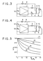
- FIG. 2 shows dynamic characteristics of the ultrasonic vibrator in an ultrasonic atomizer which incorporates the ultrasonic oscillator of the feedback resistor type built as above.
- a circle 19 represents a fundamental wave oscillation mode
- a circle 20 represents a spurious oscillation mode.
- Numerical values 38.132, 38.135, 38.141, and 45.709 represent frequencies (KHz) at the points indicated by solid dots.
- KHz frequencies
- Table 1 clearly shows the differences between the effects achieved by the ultrasonic oscillator of the feedback resistor type embodying the present invention and the effects of the existing oscillators.
- the feedback circuit is connected with feedback quantity adjusting means to adjust the feedback quantity of the signal output from the balanced circuit so that the gain of the amplifier means will become much greater than unity when the oscillator starts to oscillate, and to adjust the feedback quantity of the signal output from the balanced circuit so that the allowable frequency band of the ultrasonic vibrator is broadened when the oscillator is in the steadily oscillating condition.
- An ultrasonic oscillator is thus provided which exhibits excellent characteristics both when it starts oscillation and when it is in the steadily oscillating condition.
Landscapes
- Engineering & Computer Science (AREA)
- Mechanical Engineering (AREA)
- Apparatuses For Generation Of Mechanical Vibrations (AREA)
- Special Spraying Apparatus (AREA)
- Transducers For Ultrasonic Waves (AREA)
Claims (4)
- Ultraschalloszillator, bestehend aus einem Ultraschallvibrator (6) zum Antreiben eines Ultraschallvibratorhorns eines Ultraschallzerstäubers, einer Brückenschaltung (3,4,5), in die der Ultraschallvibrator und Kondensatorelemente einbezogen sind, so daß eine Gleichgewichtszustand in bezug auf die gedämpfte Kapazität des Ultraschallvibrator errichtet wird, und einem Verstärker (1) zur Abgabe eines Signals an die Brückenschaltung, der eine Rückkopplungsschaltung (8,9) zum zwangsläufigen Zurückführen des Ausgangssignals von der Brückenschaltung umfaßt, wobei in die Rückkopplungsschaltung Mittel (18) zum Einstellen der Rückkopplungsgröße einbezogen sind, so daß, wenn der Ultraschalloszillator die Oszillation beginnt, die Ausgangsgröße des Rückkopplungssignals von der Brückenschaltung so eingestellt wird, daß der Verstärkungsfaktor des Verstärkers viel größer als 1 ist, und, wenn sich der Oszillator im stetig oszillierenden Zustand befindet, die Ausgangsgröße des Rückkopplungssignals von der Brückenschaltung so eingestellt wird, daß die zulässige Frequenzbandbreite des Ultraschallvibrators verbreitert wird.
- Ultraschalloszillator nach Anspruch 1, dadurch gekennzeichnet, daß ein Induktivitätselement (2) zwischen den Ausgang des Verstärkers und die Brückenschaltung geschaltet ist, um eine konjugierte Anpassung mit der Lastseite zu erhalten, gesehen vom Ausgang des Verstärkers bei einer Resonanzfrequenz des Ultraschallvibrators.
- Ultraschalloszillator nach Anspruch 1 oder Anspruch 2, dadurch gekennzeichnet, daß die Rückkopplungsgrößen-Einstellmittel (18) aus einem nichtlinearen Widerstandselement bestehen.
- Ultraschalloszillator nach Anspruch 3, dadurch gekennzeichnet, daß das nichtlineare Widerstandselement aus einem Wolframwiderstand oder einem valenzgesteuerten Halbleiter vom N-Typ besteht.
Applications Claiming Priority (2)
| Application Number | Priority Date | Filing Date | Title |
|---|---|---|---|
| JP61075477A JPH0763676B2 (ja) | 1986-04-03 | 1986-04-03 | 超音波発振装置 |
| JP75477/86 | 1986-04-03 |
Publications (3)
| Publication Number | Publication Date |
|---|---|
| EP0240360A2 EP0240360A2 (de) | 1987-10-07 |
| EP0240360A3 EP0240360A3 (en) | 1988-09-28 |
| EP0240360B1 true EP0240360B1 (de) | 1991-12-18 |
Family
ID=13577415
Family Applications (1)
| Application Number | Title | Priority Date | Filing Date |
|---|---|---|---|
| EP87302925A Expired - Lifetime EP0240360B1 (de) | 1986-04-03 | 1987-04-03 | Ultraschalloszillator |
Country Status (5)
| Country | Link |
|---|---|
| US (1) | US4734659A (de) |
| EP (1) | EP0240360B1 (de) |
| JP (1) | JPH0763676B2 (de) |
| KR (1) | KR960001072B1 (de) |
| DE (1) | DE3775251D1 (de) |
Families Citing this family (3)
| Publication number | Priority date | Publication date | Assignee | Title |
|---|---|---|---|---|
| US5029268A (en) * | 1988-05-03 | 1991-07-02 | Endress U. Hauser Gmbh U. Co. | Circuit arrangement for self-excitation of a mechanical oscillation system to natural resonant oscillations |
| JPH08233581A (ja) * | 1994-12-28 | 1996-09-13 | Yoshiro Tomikawa | 静電型変換手段の駆動装置 |
| JPH08307199A (ja) * | 1995-01-11 | 1996-11-22 | Yoshiro Tomikawa | 静電型変換手段の容量成分低減回路および静電型変換手段の駆動装置ならびに検出装置 |
Family Cites Families (28)
| Publication number | Priority date | Publication date | Assignee | Title |
|---|---|---|---|---|
| US578461A (en) * | 1897-03-09 | Emile hertz | ||
| US1659538A (en) * | 1926-08-25 | 1928-02-14 | Burnoyl Heating Corp | Nozzle for liquid-fuel burners |
| US1758119A (en) * | 1927-09-24 | 1930-05-13 | Moon Axel R Le | Lawn-sprinkler nozzle |
| US1730664A (en) * | 1928-11-27 | 1929-10-08 | Kruse William John | Nozzle |
| FR786492A (fr) * | 1934-05-23 | 1935-09-03 | Pulvérisateur de liquide | |
| US2596341A (en) * | 1945-03-29 | 1952-05-13 | Owens Illinois Glass Co | Burner block and burner |
| DE861344C (de) * | 1948-10-02 | 1952-12-29 | Bosch Gmbh Robert | Einspritzventil fuer Brennkraftmaschinen |
| US2712962A (en) * | 1952-12-11 | 1955-07-12 | Esther C Goddard | Double deflecting spray nozzle |
| US3110444A (en) * | 1960-12-06 | 1963-11-12 | J S & W R Eakins Inc | Spray drying process and apparatus |
| US3373752A (en) * | 1962-11-13 | 1968-03-19 | Inoue Kiyoshi | Method for the ultrasonic cleaning of surfaces |
| US3317139A (en) * | 1965-04-13 | 1967-05-02 | Simms Group Res Dev Ltd | Devices for generating and delivering mechanical vibrations to a nozzle |
| US3469211A (en) * | 1967-10-16 | 1969-09-23 | Branson Instr | Oscillatory circuit for electro-acoustic converter with starting means |
| US3749318A (en) * | 1971-03-01 | 1973-07-31 | E Cottell | Combustion method and apparatus burning an intimate emulsion of fuel and water |
| US3756575A (en) * | 1971-07-19 | 1973-09-04 | Resources Research & Dev Corp | Apparatus for producing a fuel-air mixture by sonic energy |
| DE2239408A1 (de) * | 1972-08-10 | 1974-02-21 | Eric Charles Cottell | Verfahren und vorrichtung zur herstellung eines kraftstoff-luftgemisches mittels schallenergie |
| US4197997A (en) * | 1978-07-28 | 1980-04-15 | Ford Motor Company | Floating ring fuel injector valve |
| US4372491A (en) * | 1979-02-26 | 1983-02-08 | Fishgal Semyon I | Fuel-feed system |
| JPS5624586A (en) * | 1979-08-07 | 1981-03-09 | Fujitsu Ltd | Circuit connection checking system |
| JPS5827655Y2 (ja) * | 1979-08-25 | 1983-06-15 | 太郎 大城 | 仕切板を設けた餌入れ容器等の集合棚 |
| JPS56107956A (en) * | 1980-01-30 | 1981-08-27 | Hitachi Ltd | Solenoid fuel injection valve |
| US4350302A (en) * | 1980-09-19 | 1982-09-21 | Zurn Industries, Inc. | Liquid spray nozzle |
| US4408722A (en) * | 1981-05-29 | 1983-10-11 | General Motors Corporation | Fuel injection nozzle with grooved poppet valve |
| US4474326A (en) * | 1981-11-24 | 1984-10-02 | Tdk Electronics Co., Ltd. | Ultrasonic atomizing device |
| US4496101A (en) * | 1982-06-11 | 1985-01-29 | Eaton Corporation | Ultrasonic metering device and housing assembly |
| IT1156079B (it) * | 1982-07-15 | 1987-01-28 | Fiat Ricerche | Dispositivo di intercettamento di un fluido |
| US4541564A (en) * | 1983-01-05 | 1985-09-17 | Sono-Tek Corporation | Ultrasonic liquid atomizer, particularly for high volume flow rates |
| JPS60222552A (ja) * | 1984-04-19 | 1985-11-07 | Toa Nenryo Kogyo Kk | 超音波噴射方法 |
| US4607239A (en) * | 1985-02-28 | 1986-08-19 | The United States Of America As Represented By The Secretary Of The Army | Adjustment of the frequency-temperature characteristics of crystal oscillators |
-
1986
- 1986-04-03 JP JP61075477A patent/JPH0763676B2/ja not_active Expired - Lifetime
-
1987
- 1987-04-02 US US07/034,235 patent/US4734659A/en not_active Expired - Fee Related
- 1987-04-03 KR KR1019870003182A patent/KR960001072B1/ko not_active Expired - Lifetime
- 1987-04-03 DE DE8787302925T patent/DE3775251D1/de not_active Expired - Lifetime
- 1987-04-03 EP EP87302925A patent/EP0240360B1/de not_active Expired - Lifetime
Also Published As
| Publication number | Publication date |
|---|---|
| KR960001072B1 (ko) | 1996-01-18 |
| JPS62234581A (ja) | 1987-10-14 |
| DE3775251D1 (de) | 1992-01-30 |
| JPH0763676B2 (ja) | 1995-07-12 |
| KR870010682A (ko) | 1987-11-30 |
| US4734659A (en) | 1988-03-29 |
| EP0240360A2 (de) | 1987-10-07 |
| EP0240360A3 (en) | 1988-09-28 |
Similar Documents
| Publication | Publication Date | Title |
|---|---|---|
| US5534825A (en) | Volage-controlled oscillation circuit with an impedance element for carrier-to-noise compensation | |
| CA1070818A (en) | Sonic transducer and drive circuit | |
| JPS62150062A (ja) | 内燃機関用超音波式燃料微粒化装置の駆動回路 | |
| US4081706A (en) | Oscillatory circuit for an ultrasonic cleaning device with feedback from the piezoelectric transducer | |
| CN1065744A (zh) | 具有电子固体激励电路的机动车喇叭 | |
| US5834982A (en) | Quick starting oscillator circuit having low power consumption | |
| US5654678A (en) | Level-controlled oscillation circuit having a continuously variable impedance control circuit | |
| JPH04200282A (ja) | 超音波モータの駆動装置 | |
| EP0240360B1 (de) | Ultraschalloszillator | |
| US4584499A (en) | Autoresonant piezoelectric transformer signal coupler | |
| US4731591A (en) | Inductive proximity switch having switched capacitor for controlling hysteresis | |
| US7330083B2 (en) | Oscillator having voltage dividing circuit | |
| US20050237042A1 (en) | Switching power supply circuit and semiconductor device integrating the same | |
| US7088192B2 (en) | Inverter oscillator circuit | |
| US6072373A (en) | Voltage controlled oscillator with impedance regulation circuit including a switching element | |
| US5225793A (en) | Voltage-controlled oscillator system | |
| JP4042246B2 (ja) | 圧電発振器 | |
| US4224580A (en) | Quartz crystal oscillator | |
| US5721515A (en) | High stability single-port saw resonator oscillator | |
| US4510464A (en) | LC-switched transistor oscillator for vibrator excitation | |
| JPS626504A (ja) | 電圧制御発振器 | |
| JPH0435937Y2 (de) | ||
| JPH01202013A (ja) | 局部発振回路 | |
| JPH09162641A (ja) | 電圧制御発振器 | |
| JPH0974744A (ja) | 電源装置 |
Legal Events
| Date | Code | Title | Description |
|---|---|---|---|
| PUAI | Public reference made under article 153(3) epc to a published international application that has entered the european phase |
Free format text: ORIGINAL CODE: 0009012 |
|
| AK | Designated contracting states |
Kind code of ref document: A2 Designated state(s): DE FR GB IT SE |
|
| PUAL | Search report despatched |
Free format text: ORIGINAL CODE: 0009013 |
|
| AK | Designated contracting states |
Kind code of ref document: A3 Designated state(s): DE FR GB IT SE |
|
| 17P | Request for examination filed |
Effective date: 19890227 |
|
| 17Q | First examination report despatched |
Effective date: 19900810 |
|
| RAP1 | Party data changed (applicant data changed or rights of an application transferred) |
Owner name: ULTRASONIC ENGINEERING CO., Owner name: TONEN CORPORATION |
|
| GRAA | (expected) grant |
Free format text: ORIGINAL CODE: 0009210 |
|
| AK | Designated contracting states |
Kind code of ref document: B1 Designated state(s): DE FR GB IT SE |
|
| PG25 | Lapsed in a contracting state [announced via postgrant information from national office to epo] |
Ref country code: IT Free format text: LAPSE BECAUSE OF FAILURE TO SUBMIT A TRANSLATION OF THE DESCRIPTION OR TO PAY THE FEE WITHIN THE PRE;WARNING: LAPSES OF ITALIAN PATENTS WITH EFFECTIVE DATE BEFORE 2007 MAY HAVE OCCURRED AT ANY TIME BEFORE 2007. THE CORRECT EFFECTIVE DATE MAY BE DIFFERENT FROM THE ONE RECORDED.SCRIBED TIME-LIMIT Effective date: 19911218 Ref country code: SE Effective date: 19911218 |
|
| ET | Fr: translation filed | ||
| REF | Corresponds to: |
Ref document number: 3775251 Country of ref document: DE Date of ref document: 19920130 |
|
| PLBE | No opposition filed within time limit |
Free format text: ORIGINAL CODE: 0009261 |
|
| STAA | Information on the status of an ep patent application or granted ep patent |
Free format text: STATUS: NO OPPOSITION FILED WITHIN TIME LIMIT |
|
| 26N | No opposition filed | ||
| PGFP | Annual fee paid to national office [announced via postgrant information from national office to epo] |
Ref country code: GB Payment date: 19950324 Year of fee payment: 9 |
|
| PGFP | Annual fee paid to national office [announced via postgrant information from national office to epo] |
Ref country code: DE Payment date: 19950410 Year of fee payment: 9 |
|
| PGFP | Annual fee paid to national office [announced via postgrant information from national office to epo] |
Ref country code: FR Payment date: 19950411 Year of fee payment: 9 |
|
| PG25 | Lapsed in a contracting state [announced via postgrant information from national office to epo] |
Ref country code: GB Effective date: 19960403 |
|
| GBPC | Gb: european patent ceased through non-payment of renewal fee |
Effective date: 19960403 |
|
| PG25 | Lapsed in a contracting state [announced via postgrant information from national office to epo] |
Ref country code: FR Effective date: 19961227 |
|
| PG25 | Lapsed in a contracting state [announced via postgrant information from national office to epo] |
Ref country code: DE Effective date: 19970101 |
|
| REG | Reference to a national code |
Ref country code: FR Ref legal event code: ST |