EP0240455B2 - Drehzahlregelung für einen bürstenlosen Motor - Google Patents
Drehzahlregelung für einen bürstenlosen Motor Download PDFInfo
- Publication number
- EP0240455B2 EP0240455B2 EP87630048A EP87630048A EP0240455B2 EP 0240455 B2 EP0240455 B2 EP 0240455B2 EP 87630048 A EP87630048 A EP 87630048A EP 87630048 A EP87630048 A EP 87630048A EP 0240455 B2 EP0240455 B2 EP 0240455B2
- Authority
- EP
- European Patent Office
- Prior art keywords
- delay
- time
- signal
- interval
- rotor
- Prior art date
- Legal status (The legal status is an assumption and is not a legal conclusion. Google has not performed a legal analysis and makes no representation as to the accuracy of the status listed.)
- Expired - Lifetime
Links
Images



Classifications
-
- H—ELECTRICITY
- H02—GENERATION; CONVERSION OR DISTRIBUTION OF ELECTRIC POWER
- H02P—CONTROL OR REGULATION OF ELECTRIC MOTORS, ELECTRIC GENERATORS OR DYNAMO-ELECTRIC CONVERTERS; CONTROLLING TRANSFORMERS, REACTORS OR CHOKE COILS
- H02P6/00—Arrangements for controlling synchronous motors or other dynamo-electric motors using electronic commutation dependent on the rotor position; Electronic commutators therefor
- H02P6/14—Electronic commutators
- H02P6/15—Controlling commutation time
Definitions
- the present invention relates to an electronic control for the commutation of brushless DC motors and further provides means to vary the speed of the motor by varying the duty cycle of electrical conduction within a phase winding of the motor.
- the timing of the conductance is such that it will occur in an optimum range within the torque cycle of a phase winding to maximize motor efficiency over a wide speed range.
- the present invention relates in particular to a digital speed control circuit according to the preamble of claim 1, to an electronically controlled motor system according to the preamble of claim 12, and to a method of controlling a motor according to the preamble of claim 16, as they are known from DE-C-2 052 695.
- US-A-4400654 discloses a digital speed control for a brushless DC motor comprising features of the preambles of the independent claims.
- the herein-described motor control circuit utilizes a centered pulse turn-on concept which is adaptable to operation with any number of phases in a motor.
- Each phase has its own on-time and delay time data generation. Based on this timing data each phase winding is energized only for a carefully selected portion of the time said phase winding is capable of generating torque for the desired direction of rotation of the rotor. Multiple phases, even if the torque cycles are overlapping, may be energized independently when most appropriate for each.
- the herein-described control could also be connected to energize each phase winding for the identical period curing motor rotation such that all phases are energized for the same duty cycle adjusted to be initiated at the correct start time.
- torque in a unipolar driven motor may be applied by directing current in a single direction through a winding of the motor at a selected time relative to the rotor position.
- the force applied to the rotor with respect to the current applied increases and decreases during this interval in which torque will be produced,
- By sensing the rotor position through the rotational angle during which current may be applied it is possible to apply appropriate electrical power at the point where it is most efficient.
- By adjusting the length of time the electrical power is applied and the delay interval from the beginning of the potential torque producing angle to the time when the current is actually applied it is possible to control both the amount of power applied and the speed of the motor.
- An advantage of using a digitally-controlled motor speed control is that all inputs and outputs are compatible for use with a microprocessor control.
- the invention is described relative to a unipolar-driven motor, it is likewise applicable for a bipolar-driven motor. Some additional logic may be necessary to determine when to appropriately apply current in a reverse direction to achieve the bipolar effect. Additionally, it may be desirable to have additional position sensing devices to indicate a different point on the motor's torque cycle on which the delay interval should begin.
- a still further object of the present invention is to provide a brushless DC motor control which acts to apply positive torque at the most efficient portion of the torque cycle.
- the speed control circuit receives an input signal from a rotor position detecting means and provides an electrical pulse of duration and timing such that as the pulse is applied to an energizing circuit of the motor, the current will occur within the windings of the motor at such time with respect to the rotor in the motor to produce maximum torque and to sustain a preselected speed.
- an electrical pulse can be made to occur at any time during which a phase can produce torque.
- the control circuit for a brushless DC motor includes a rotor position detecting means that provides a signal input to a frequency multiplier circuit and to a phase timing circuit, a delay-time register and an on-time register, each of which receives an input signal from the frequency multiplier, a phase timing circuit which receives a first signal from the rotor position detecting means, a second signal from the frequency multiplier and from the delay-time register and the on-time register, a driver circuit for each phase winding of the motor that receives a signal from the phase timing circuit and which supplies a pulse of current to the motor winding when the rotor within the motor is at one optimum position to produce maximum torque and for a duration to sustain a preselected rotor speed.
- the apparatus as described hereinafter will refer to a three-phase unipolar, brushless DC motor circuit control. It is to be understood that this circuit may likewise be utilized with motors having different numbers of circuits, with bipolar as well as unipolar motors, and with motors having a different number of phases.
- Figure 1 comprises a series of waveform signals to illustrate the inputs to and the functions of the control circuit.
- These position sensing elements are located so as to provide a signal for each phase at such time as the rotor is in position to result in producing positive torque, that will cause rotation in the desired direction from the energization of that particular phase winding.
- a three-phase motor as illustrated here there will be three position sensing devices and, therefore, three signals as represented by waveforms 10, 12, and 14.
- position sense signal A there may be seen that there is a point labeled PA1, which is indicative of the rotor position at which the current in phase A will begin producing positive torque.
- Position PA2 indicates the rotor position at which current in phase A will begin producing negative torque.
- PB1 and PB2 indicate the positions at which current in phase B will begin producing positive torque and negative torque, respectively.
- PC1 and PC2 likewise indicate the positions at which current in phase C will begin producing positive and negative torque, respectively.
- the center waveform of Figure 1 is a frequency multiplier output identified as waveform 16.
- This frequency multiplier output is not to scale.
- this frequency multiplier output is a multiple of the position sense signal frequency such as 512 times the position sense signal frequency thereby dividing each torque cycle of the phase into 512 increments.
- Waveforms 18, 20, and 22 shown in the bottom portion of Figure 1 are labeled phase A timing output, phase B timing output and phase C timing output, respectively. These three waveforms depict the signal that is supplied from the control circuit to a power driver, thus energizing a phase or winding in the motor.
- the time interval labeled from T01 to T02 is the delay time generated by the control circuit. This delay interval starts at the time when a phase is capable of producing positive torque and lasts for one-half the number of counts of the frequency multiplier that is stored in the delay time register. In other words, this is the time interval between when positive torque may be produced and when positive torque is actually produced by the application of current to the appropriate winding.
- the time interval T02 to T03 is the on-time generated by the control circuit. This time interval starts immediately after the delay time interval has elapsed and lasts for the number of counts of the frequency multiplier output that is stored in the on-time register or until the phase is no longer capable of producing positive torque. It may be seen that the interval indicated to be T02 to T03 is contained within the interval that position sense signal A identifies as that region in which positive torque is produced (PA1 to PA2).
- a selected interval during which the winding may be energized is determined by knowing both the delay-time interval at the start of the period during which positive torque may be produced, labeled PA1, PB1 or PC1 and the on-time interval during which power is applied to the phase.
- This on-time interval for each phase is that interval represented between times T02 and T03.
- the on-time pulse can be positioned anywhere within the time during which a phase can produce positive torque. This will allow optimization of the commutation for improved motor efficiency. In most applications, efficiency is maximized by centering the on-time pulse within the positive portion of the torque cycle of a phase. In some applications it may be desirable to offset the on-time pulse. This also allows for motors wherein the torque intervals overlap to allow separate phases to be energized at distinct times by providing separate delay intervals for each phase, such that it is possible to energize the appropriate winding at the best time for that phase.
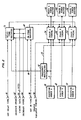
- position sense indicators 30, 40, 50 are located to detect the position at which positive torque may be produced by a phase and to generate a signal in response thereto. These signals are directed to phase A timing 34, phase B timing 44 and phase C timing 54, respectively such that the appropriate timing control circuits know the rotor position and when positive torque may be produced.
- Signal 31 generated by position sense A is also directed to frequency multiplier 32.
- Frequency multiplier 32 acts to generate a high frequency signal dependent upon the motor speed, which signal 33 is conducted to phase A timing, phase B timing and phase C timing 34, 44 and 54, respectively. Additionally, the frequency multiplier generates a speed change clock signal 88 which is directed to on-time register 60 and delay-time register 70.
- delay-time register 70 having inputs from set delay time 80 and speed change clock signal 88 as well as increase speed signal 82, timing data input 84 and decrease speed signal 86.
- the on-time register has similar inputs except for the substitute of set on-time 90 instead of set delay-time 80.
- the delay-time register is utilized to store the time interval for establishing the delay interval between the start of the positive torque producing period and the time when the current is supplied to the winding.
- the on-time register is utilized to store timing data to control the length of time the current is supplied to the winding. It can be seen that output signals from delay-time register 70 and on-time register 60 are directed to each of the phase timing circuits 34, 44 and 54.
- Each phase timing circuit utilizes the input information and generates a signal to respective power drivers, phase A power driver 36, phase B power driver 46 and phase C power driver 56.
- the signal is generated for the duration of the timer when it is desirable to have the appropriate power driver supply current to the identified phase winding.
- FIG. 6 there may be seen permanent magnet rotor 100 located adjacent to stator windings 102.
- Position sense blocks A, B and C labeled 30, 40 and 50, respectively, are connected through the remainder of the control circuit (not shown) to control application of power to the stator windings.
- Transistors 136, 146 and 156 (shown to indicate a type of power driver) are used respectively such that power is gated to the stator windings in response to the signals generated from the sensors of the position sense blocks.
- the various power drivers may be other types of switching devices than the transistors shown.
- phase timing circuit shown in Figure 4 the delay-time and on-time registers shown in Figure 5 and the frequency multiplier circuit as shown in Figure 3.
- position sense signal A from block 30 is gated to phase-locked loop 32.
- the position sense A signal is used as a reference that has a frequency equal to the frequency of the torque cycle of phase A for the speed at which the motor is turning.
- this phase locked loop device includes a frequency divider having a feedback path. A purely digital approach could be used in cases where implementation through a single integrated circuit was desired and would thusly avoid the need for the RC components for setting the phase lock loop's voltage controlled oscillator frequency range and filtering of the control voltage.
- the circuit as shown compares the position sense A input frequency to a frequency that is produced by a voltage controlled oscillator (VCO) that has been divided by a factor of 512.
- VCO voltage controlled oscillator
- the control voltage to the VCO is varied until the two inputs are the same frequency.
- the sense A frequency (33) is 512 times the electrical frequency of the torque cycle of phase A. Since the VCO frequency is self-adjusting, this frequency multiplication factor is constant over the operating speed range of the motor.
- a speed change clock signal 88 is at a frequency one-half the position sense A frequency. Other frequencies would work for the speed change clock, but this ratio works well in many cases.
- the sense A frequency multiplied by 512 is the output signal on line 33.
- On-time register 150 is shown toward the top of Figure 5 and delay-time register 160 is shown towards the bottom. Both registers are eight-bit, presettable, up-down counters. Connected to on-time register 150 is set on-time input 90 and a series of timing data inputs 114. A group of signals 110 represented by on-time data is generated by on-time register 150. This on-time data signal is gated back through NAND gate 158, and OR gate 159 through another series of gates to prevent the on-time register from "rolling over" when it is incremented and decremented. In other words, the clocked values in the up-down counter may vary from zero to 255, however the counter is not allowed to index from 255 to zero or from zero to 255. At either end of the counter further incrementing or decrementing is inhibited.
- delay-time register 160 receives a set delay time input 80 and input from timing data inputs 114.
- a group of signals 112 represented by delay-time data is generated and this output is likewise gated through NAND gate 168 and OR gate 169, through a gate matrix to likewise control "rolling over" of the delay-time register.
- Speed change clock signal 88 is directed through AND gates 152 and 162, respectively to the clock input to each counter.
- Each counter additionally has an up-down increment-decrement selector which is energized by decrease speed signal 86.
- a typical motor might have three or four preset speeds. These preset speeds would each have appropriate preset timing data which is represented by timing data input signal 114.
- the operator might have a series of buttons, one each of which will generate an appropriate timing data input to both the counters to obtain the desired motor speed.
- the set on-time signal 90 or the set delay-time signal 80 is provided which will latch the data from the timing data inputs into the respective registers. The registers then provide that data as the on-time data or delay-time data output for use by the remainder of the circuit.
- a decrease speed signal (86) is provided. This signal is connected to change the direction in which both counters increment or decrement and provides a signal to AND gates 157 and 167 and from there through OR gates 164 and 154 to AND gates 152 and 162 through which an input signal is provided to the counters with each speed change clock signal. In this manner both counters may be incremented or decremented to adjust to the appropriate on-time and delay-time intervals.
- NAND and OR gates 158, 159 and 169 and 168 are provided to prevent "roll over”. Their operation is such that NAND gate 158, for instance will generate a high signal until all of the data lines D3-D7 become high. At that point, NAND gate 158 will generate a low signal which when received by AND gate 157 will have AND gate 157 generate a low signal notwithstanding that the decrease speed signal is still high. With one of these signals low, OR gate 154 will be low and no output will be provided to the on-time register to further increment the on-time register. Hence, in this manner 248 is the highest on-time data that may occur.
- OR gate 159 is connected to data lines D3-D7 and OR gate 159 generates a high signal until all of said data lines are low. Under these circumstances, OR gate 159 goes low and likewise AND gate 156 will be low notwithstanding that the increase speed signal is on. In this manner the on-time register may not decrement below the minimum value of seven.
- the delay-time register 160 uses similar gates to control "roll over" in a similar manner.
- on-time data input 110 from the on-time register 150 of Figure 5 and the delay-time data 112 from the delay-time register 160 of Figure 5.
- the appropriate on-time data and delay-time data are received by presettable eight-bit up counter 200 and presettable seven-bit down counter 220. Each of these is preset to the appropriate data input.
- Position sense input signal 31 is shown connected to the preset input to both the presettable eight-bit up counter 200 and the presettable seven-bit down counter 220.
- the 512X position sense input frequency signal 33 is shown gated through AND gate 264 to the clock input of up counter 200 and through AND gate 260 to the clock input of down counter 220.
- the terminal count output from up counter 200 is gated to AND gate 264 and to exclusive OR gate 240.
- the terminal count output from down counter 220 is gated to exclusive OR gate 240, to AND gate 260 and through inverter 262 to AND gate 264.
- Position sense input 31 is also connected to AND gate 246 and therethrough to OR gate 258 to power driver for phase A 36.
- Variable timing enable input 92 is connected through inverter 244 to AND gate 246 and to AND gate 242.
- variable timing enable input 92 when the variable timing enable input 92 is not energized indicating that the variable timing feature is not desired, then the variable timing circuit will be disabled since AND gate 242 will have a low input. In such event the position sense signal 31 will be gated directly to AND gate 246 and the low signal from variable timing enable signal 92 will be inverted in inverter 244 and also directed to AND gate 246. In this manner AND gate 246 will go high whenever the position sense signal is high. This high signal will be gated through OR gate 258 to drive power driver 36. Hence, when the variable timing enable signal is off, the power driver is driven in response to position sense input 33.
- variable timing enable signal When the variable timing enable signal is on, the power driver is driven in response to the exclusive OR gate 240 output.
- inverter 244 converts said signal to a low signal thereby effectively preventing AND gate 246 from energizing power driver 36 notwithstanding the position sense input signal.
- the position sense input acts, when it goes low, to preset both counters by latching the values obtained from the on-time register and the delay time register into the counters. At the same time the terminal count output of each counter goes high. Since both terminal count outputs are high, both inputs to exclusive OR gate 240 will be high and the power driver will not be energized.
- connection from the delay-time data to the presettable down counter is such that the delay-time from the delay-time register is divided in half before being provided to the down counter. This is accomplished by simply ignoring the least significant bit from the data and using a seven-bit down counter instead of an eight-bit down counter. The purpose of this is to allow the set on-time and set delay-time inputs to be activated simultaneously. If the on-time for a phase is to be centered within the positive torque portion of the cycle, by dividing by two, half of the off-time is placed at the beginning of the positive torque portion of the cycle, and half is placed at the end of the positive torque portion of the cycle. Hence, the on-time interval is centered in the positive torque portion of the cycle by dropping the least significant bit from the delay-time register.
- the two presettable counters are held in the preset condition with the up counter containing the on-time data and the down counter containing the delay-time data.
- the up counter increments to its maximum count
- the terminal count output then switches from high to low.
- the down counter decrements to zero, its terminal output switches from high to low. Otherwise, the terminal count pin or output in each counter is high.
- the down counter begins counting at the rate of 512 times the position sense input frequency.
- the up counter is inhibited from counting because the down counter's terminal output is inverted and used to gate the 512X clocks into the up counter.
- the output of the exclusive OR gate is low because both terminal count pins are high. Both inputs to the exclusive OR gate remain high until the down counter decrements to zero. At that time, the terminal count output goes low and inhibits any additional clock pulses to the down counter by AND gate 260. At the same time the terminal count output is inverted at inverter 262 and begins allowing 512X clock pulses through AND gate 264 into the up counter.
- Additional means may be provided to allow the timing data input to the registers to be varied independently. In this matter, the positioning of the on-time pulse may be varied within the positive torque producing portion of the cycle. Furthermore, circuit means may be added to allow one set of registers to control each phase of the motor.
Landscapes
- Engineering & Computer Science (AREA)
- Power Engineering (AREA)
- Control Of Motors That Do Not Use Commutators (AREA)
Claims (18)
- Digitale Drehzahlsteuerschaltung für einen Elektromotor mit einer Phasenwicklung, die selektiv erregt wird, um Kraft auf einen Rotor aufzubringen, umfassend:dadurch gekennzeichnet, daß die Logikeinrichtung Zähler (200, 220) aufweist, die mit Verzögerungszeit-Daten bzw. mit Ein-Zeit-Daten unabhängig voneinander voreingestellt sind, so daß die Dauer des Verzögerungsintervalls und die des Ein-Zeitintervalls unabhängig sind, und die von den Zählern gezählten Taktfrequenzen proportional zu der Frequenz des Rotorstellungs-Eingangssignals ist.eine Einrichtung (30, 40, 50) zum Empfangen eines Eingangssignals, welches die Rotorstellung angibt;eine Logikeinrichtung (34, 44, 54) zur Erzeugung eines Treibersignals, um das Erregen der Phasenwicklung zu veranlassen,eine Verzögerungseinrichtung (70) zur Schaffung eines Verzögerungsintervalls; undeine Ein-Zeiteinrichtung (60) zum Schaffen eines Ein-Zeitintervalls, in welchem eine Phasenwicklung erregt sein sollte;wobei die Logikeinrichtungdie Verzögerungseinrichtung anstößt, das Verzögerungsintervall bei Empfang des Eingangssignals bereitzustellen, und die Ein-Zeiteinrichtung nach Verstreichen des Verzögerungsintervalls anstößt,und die Logikeinrichtung außerdem bewirkt, daß das Treibersignal für die Dauer des Ein-Zeitintervalls erzeugt wird,
- Steuerschaltung nach Anspruch 1, bei der die Verzögerungseinrichtung (70) außerdem ein Verzögerungszeitregister (160) aufweist, welches an den Verzögerungszähler angeschlossen ist, um in dem Verzögerungszähler einen Wert zwischenzuspeichern, und eine Takteinrichtung (31, 32) aufweist, um den Verzögerungszähler zur Bildung des Verzögerungsintervalls weiterzuschalten.
- Steuerschaltung nach Anspruch 2, bei der die Ein-Zeiteinrichtung außerdem aufweist:ein Ein-Zeit-Register (150), das an den Ein-Zeit-Zähler angeschlossen ist, um in dem Ein-Zeit-Zähler einen Wert zwischenzuspeichern, und eine Einrichtung (150) zum Empfangen eines Taktsignals, um den Ein-Zeit-Zähler zur Bildung des Ein-Zeitintervalls weiterzuschalten.
- Steuerschaltung nach Anspruch 3, umfassend:eine Zeitsteuerdateneingabeeinrichtung (114), die so verschaltet ist, daß sie ausgewählte Werte an das Verzögerungszeitregister und das Ein-Zeit-Register liefert.
- Steuerschaltung nach Anspruch 3, bei der das Verzögerungszeitregister und das Ein-Zeit-Register aufweisen:eine Eingabeeinrichtung (110, 112) zum Inkrementieren oder Dekrementieren der Register.
- Steuerschaltung nach Anspruch 5, bei der das Verzögerungszeitregister und das Ein-Zeit-Register außerdem aufweisen:eine Steuereinrichtung (152, 154, 156-159, 162, 164, 166-169) zum Verhindern, daß die Register "überlaufen".
- Steuerschaltung nach Anspruch 1, bei der die Einrichtung (30, 40, 50) zum Empfangen eines Eingangssignals einen Halleffekt-Sensor aufweist, der so angeordnet ist, daß er ein Signal erzeugt, wenn das Zuspeisen von Strom zu der Phasenwicklung imstande ist, an dem Rotor ein positives Drehmoment hervorzurufen.
- Steuerschaltung nach Anspruch 1, bei der der Elektromotor mehrere Wicklungen aufweist, wobei eine Einrichtung (30, 40, 50) zum Empfangen eines Eingangssignals, die Verzögerungseinrichtung (70), die Ein-Zeiteinrichtung (60) und die Logikeinrichtung (34, 44, 54) für jede Wicklung vorgesehen sind.
- Steuerschaltung nach einem der Ansprüche 1 bis 8, bei der:die Logikeinrichtung eine Phasenzeitsteuerschaltung (34) aufweist, die von der Rotorstellungs-Erfassungseinrichtung ein Signal (31) empfängt, die von einer Frequenzvervielfacherschaltung (32) ein Signal empfängt und Signale von der Verzögerungseinrichtung und der Ein-Zeiteinrichtung empfängt, und basierend auf den Werten der empfangenen Signale ein Ausgangssignal erzeugt; undfür jede Phasenwicklung des Motors eine Treiberschaltung (36, 46, 56) vorgesehen ist, die das Ausgangssignal von der Phasenzeitsteuerschaltung empfängt und einen Stromimpuls an die Motorwicklung bei optimaler Stellung eines Rotors innerhalb des Motors gibt, um ein maximales Drehmoment und für eine Dauer zu erzeugen und eine vorbestimmte Rotordrehzahl aufrechtzuerhalten.
- Steuerschaltung nach Anspruch 9, bei der der Verzögerungszeitzähler (220) mit einer Geschwindigkeit getaktet wird, die von dem Frequenzvervielfacher (32) festgelegt wird, um das Verzögerungsintervall zwischen dem Empfang eines Signals von der Rotorstellungs-Erfassungseinrichtung (30, 40, 50) und der Erzeugung eines Ausgangssignals zu bestimmen.
- Steuerschaltung nach Anspruch 10, bei der die Phasenzeitsteuerschaltung außerdem aufweist:einen Ein-Zeit-Zähler (200), der mit einer Geschwindigkeit getaktet wird, die durch den Frequenzvervielfacher (32) bestimmt wird, nachdem das Verzögerungsintervall verstrichen ist, wobei das Ausgangssignal der Treiberschaltung signalisiert, der Wicklung während der Zeitspanne, in der der Ein-Zeit-Zähler zählt, Leistung zuzuspeisen.
- Elektronisch gesteuerter Motor mit einem drehbeweglich gelagerten Rotor und einem Motorfeld (102) umfassend:wobei die Logikeinrichtung außerdem enthält:eine Rotorstellungs-Erfassungseinrichtung (30, 40, 50) zum Erzeugen eines Stellungssignals,eine Treiberschaltung (36, 46, 56) für jede Wicklung des Motors, welche ein Treibersignal empfängt und einen Stromimpuls für die Dauer des Treibersignals an die Wicklung gibt,wobei die Rotorstellungs-Erfassungsschaltung das Stellungssignal erzeugt, wenn der Rotor in Bezug auf eine Wicklung eine solche Stellung einnimmt, daß das Einspeisen von Strom in die Wicklung dazu führt, daß auf den Rotor ein positives Drehmoment aufgebracht wird,eine Logikeinrichtung (34, 44, 54), verschaltet zum Empfang des Stellungssignals und zum Erzeugen eines Treibersignals;dadurch gekennzeichnet, daß die Logikeinrichtung Zähler (200, 220) aufweist, die mit Verzögerungszeit-Daten bzw. mit Ein-Zeit-Daten unabhängig voneinander voreingestellt sind, so daß die Dauer des Verzögerungsintervalls und die des Ein-Zeitintervalls unabhängig sind, und die von den Zählem gezählte Taktfrequenz proportional zu der Frequenz des Rotorstellungs-Eingangssignals ist.eine Verzögerungseinrichtung (70) zum Festlegen eines Verzögerungsintervalls zwischen dem Empfang des Stellungssignals und der Erzeugung des Treibersignals,eine Ein-Zeiteinrichtung (60) zum Bestimmen der Dauer des Treibersignals;
- Motor nach Anspruch 12, bei dem die Verzögerungseinrichtung ein Verzögerungsregister (160) aufweist, welches voreingestellte Werte enthält, und einen Verzögerungszähler (220) enthält, der zur Bestimmung des Verzögerungsintervalls von dem Verzögerungsregister-Wert ausgehend mit einer bekannten Geschwindigkeit zählt.
- Motor nach Anspruch 13, bei dem der Verzögerungszähler (220) an das Verzögerungsregister (160) derart angeschlossen ist, daß der Verzögerungszähler einen Wert empfängt, der etwa der Hälfte des Werts in dem Verzögerungsregister entspricht.
- Motor nach Anspruch 14, bei dem die Ein-Zeiteinrichtung (60) ein Ein-Zeit-Register (150) aufweist, welches Voreinstellwerte enthält, ferner einen Ein-Zeit-Zähler (200), der von dem Wert in dem Ein-Zeit-Register ausgehend mit bekannter Geschwindigkeit gezählt wird, um das Ein-Zeitintervall festzulegen.
- Verfahren zum Steuern eines Motors mit einem Rotor und mindestens einer Wicklung (112), umfassend die Schritte:gekennzeichnet durch die Schritte:Bestimmen (70) eines Verzögerungsintervalls, welches bei Erfassung eines Signals beginnt; undBestimmen (60) eines Ein-Zeitintervalls, das im Anschluß an das Verstreichen des Verzögerungsintervalls beginnt, und Erzeugen eines Treibersignals während dieses Ein-Zeitintervalls; undZuspeisen (34, 44, 54) von Leistung zu der Wicklung, um den Rotor anzutreiben, sobald das Treibersignal erfaßt ist;Fühlen (30, 40, 50), wenn der Rotor sich in einer Stellung relativ zu der Wicklung bewegt, in der das Zuspeisen von Strom zu der Wicklung zu dem Aufbringen eines positiven Drehmoments auf den Rotor führt, und Erzeugen des erwähnten Signals;Bestimmen des Verzögerungsintervalls und des Ein-Zeitintervalls mit Hilfe von Zählern (200, 220), Voreinstellen der Zähler mit Verzögerungszeit-Daten bzw. Ein-Zeit-Daten unabhängig voneinander, so daß die Zeitspannen des Verzögerungsintervalls und des Zeitintervalls unabhängig sind, und Zählen einer Taktfrequenz mit jedem Zähler, welche proportional zu der Frequenz des Rotorstellungs-Eingangssignals ist.
- Verfahren nach Anspruch 16, bei dem die Schritte des Bestimmens des Verzögerungsintervalls und des Bestimmens des Ein-Zeitintervalls in Kombination dazu dienen, das Treibersignal während desjenigen Abschnitts der Rotordrehung bereitzustellen, in welchem das Drehmoment für den der Wicklung zugespeisten Strom maximiert wird.
- Verfahren nach Anspruch 16, bei dem die Schritte des Bestimmens des Verzögerungsintervalls und des Bestimmen des Ein-Zeitintervalls zur Steuerung der Rotordrehzahl dienen.
Applications Claiming Priority (2)
| Application Number | Priority Date | Filing Date | Title |
|---|---|---|---|
| US06/846,397 US4720663A (en) | 1986-03-31 | 1986-03-31 | Brushless motor speed control |
| US846397 | 1986-03-31 |
Publications (4)
| Publication Number | Publication Date |
|---|---|
| EP0240455A2 EP0240455A2 (de) | 1987-10-07 |
| EP0240455A3 EP0240455A3 (en) | 1988-10-26 |
| EP0240455B1 EP0240455B1 (de) | 1993-02-03 |
| EP0240455B2 true EP0240455B2 (de) | 1999-09-22 |
Family
ID=25297813
Family Applications (1)
| Application Number | Title | Priority Date | Filing Date |
|---|---|---|---|
| EP87630048A Expired - Lifetime EP0240455B2 (de) | 1986-03-31 | 1987-03-30 | Drehzahlregelung für einen bürstenlosen Motor |
Country Status (5)
| Country | Link |
|---|---|
| US (1) | US4720663A (de) |
| EP (1) | EP0240455B2 (de) |
| CA (1) | CA1284671C (de) |
| DE (1) | DE3783931T3 (de) |
| MX (1) | MX165600B (de) |
Families Citing this family (22)
| Publication number | Priority date | Publication date | Assignee | Title |
|---|---|---|---|---|
| US5023531A (en) * | 1988-05-19 | 1991-06-11 | Arx, Inc. | Dual hybrid demand refrigeration control apparatus |
| US4897583A (en) * | 1989-03-07 | 1990-01-30 | Sundstrand Corporation | Variable speed variable torque brushless DC motor |
| JP2794471B2 (ja) * | 1989-11-24 | 1998-09-03 | 日本電子テクニクス株式会社 | 電子顕微鏡 |
| US5663624A (en) * | 1992-03-05 | 1997-09-02 | Hewlett-Packard Company | Closed-loop method and apparatus for controlling acceleration and velocity of a stepper motor |
| US6348752B1 (en) * | 1992-04-06 | 2002-02-19 | General Electric Company | Integral motor and control |
| US5270622A (en) * | 1992-04-13 | 1993-12-14 | Smith & Nephew Dyonics, Inc. | Brushless motor control system |
| US5285135A (en) * | 1992-09-23 | 1994-02-08 | Sgs-Thomson Microelectronics, Inc. | Automatic adjustment of commutation delay for brushless DC motor for improved efficiency |
| US5845045A (en) * | 1993-11-28 | 1998-12-01 | Papst-Motoren Gmbh & Co. Kg | Method and apparatus for DC motor speed control |
| KR0136976B1 (ko) * | 1993-12-08 | 1998-06-15 | 김광호 | 무정류자모터의 운전제어장치 및 방법 |
| JP3256840B2 (ja) * | 1997-02-04 | 2002-02-18 | 株式会社ゼクセルヴァレオクライメートコントロール | ブラシレスモータの駆動制御装置 |
| US6331757B1 (en) * | 1998-06-19 | 2001-12-18 | Siemens Canada Limited | Staggered pulse width modulation apparatus and method for EMI minimization in motor |
| US6605912B1 (en) | 1998-06-25 | 2003-08-12 | Delphi Technologies, Inc. | Method for controlling a permanent magnet motor |
| US6487033B1 (en) | 1998-09-25 | 2002-11-26 | Seagate Technology Llc | Motor speed observer for data protection in a disc drive |
| US6838849B2 (en) * | 2003-05-27 | 2005-01-04 | Sunonwealth Electric Machine Industry Co., Ltd. | Serially connected double-phase full-wave brushless dc motor |
| JP4454328B2 (ja) * | 2004-01-29 | 2010-04-21 | 三洋電機株式会社 | モータ駆動装置、集積回路、モータ駆動方法 |
| CN100471014C (zh) * | 2004-08-10 | 2009-03-18 | 建准电机工业股份有限公司 | 串联式双相全波无刷直流马达 |
| US8766578B2 (en) | 2012-02-27 | 2014-07-01 | Canadian Space Agency | Method and apparatus for high velocity ripple suppression of brushless DC motors having limited drive/amplifier bandwidth |
| US10488172B1 (en) | 2017-10-18 | 2019-11-26 | Zoox, Inc. | Independent control of vehicle wheels |
| US10759416B1 (en) | 2017-10-18 | 2020-09-01 | Zoox, Inc. | Independent control of vehicle wheels |
| US11136021B1 (en) | 2017-10-18 | 2021-10-05 | Zoox, Inc. | Independent control of vehicle wheels |
| US10821981B1 (en) | 2017-10-18 | 2020-11-03 | Zoox, Inc. | Independent control of vehicle wheels |
| EP4181387B1 (de) * | 2021-11-15 | 2025-01-08 | Siemens Schweiz AG | Halbschrittmotortreiber |
Family Cites Families (19)
| Publication number | Priority date | Publication date | Assignee | Title |
|---|---|---|---|---|
| GB1049594A (en) * | 1964-04-29 | 1966-11-30 | Rank Bush Murphy Ltd | Movement control servomechanism |
| JPS4882809A (de) * | 1972-02-03 | 1973-11-06 | ||
| US3950682A (en) * | 1974-12-19 | 1976-04-13 | International Business Machines Corporation | Digital dc motor velocity control system |
| US4096422A (en) * | 1975-12-03 | 1978-06-20 | E. I. Du Pont De Nemours And Company | Motor control system |
| US4107595A (en) * | 1977-01-24 | 1978-08-15 | Teletype Corporation | Current control system for a stepping motor |
| JPS5837571B2 (ja) * | 1977-01-25 | 1983-08-17 | 松下電器産業株式会社 | 回転体の回転速度制御装置 |
| US4398339A (en) * | 1977-04-15 | 1983-08-16 | Supertex, Inc. | Fabrication method for high power MOS device |
| US4492903A (en) * | 1977-05-23 | 1985-01-08 | Nu-Tech Industries, Inc. | Optimum efficiency brushless DC motor |
| NL7711634A (nl) * | 1977-10-24 | 1979-04-26 | Philips Nv | Tachometerstelsel. |
| AU515771B2 (en) * | 1978-01-17 | 1981-04-30 | Sony Corporation | Digital servo circuit |
| JPS54102474A (en) * | 1978-01-27 | 1979-08-11 | Sony Corp | Digital servo circuit |
| JPS56125994A (en) * | 1980-03-07 | 1981-10-02 | Olympus Optical Co Ltd | Motor unit |
| US4400654A (en) * | 1981-03-27 | 1983-08-23 | Magnetic Peripherals Inc. | Digital speed control for a brushless DC motor |
| US4353016A (en) * | 1981-04-22 | 1982-10-05 | Minnesota Mining And Manufacturing Company | Linear motor control system for brushless DC motor |
| US4414495A (en) * | 1981-10-27 | 1983-11-08 | Kashifuji Works, Ltd. | Synchronism equipment for gear cutting machines |
| US4564795A (en) * | 1981-12-21 | 1986-01-14 | Beckman Instruments, Inc. | Motor speed control system |
| US4525657A (en) * | 1983-03-09 | 1985-06-25 | Matsushita Electric Industrial Co., Ltd. | Torque ripple compensation circuit for a brushless D.C. motor |
| JPS60134310A (ja) * | 1983-12-22 | 1985-07-17 | Hitachi Ltd | モータ制御装置 |
| US4584505A (en) * | 1984-06-14 | 1986-04-22 | Yeongchoon Chung | Torque-speed control system for asynchronous D.C. brushless motor |
-
1986
- 1986-03-31 US US06/846,397 patent/US4720663A/en not_active Expired - Lifetime
-
1987
- 1987-03-11 CA CA000531719A patent/CA1284671C/en not_active Expired - Lifetime
- 1987-03-30 EP EP87630048A patent/EP0240455B2/de not_active Expired - Lifetime
- 1987-03-30 DE DE3783931T patent/DE3783931T3/de not_active Expired - Fee Related
- 1987-03-31 MX MX005809A patent/MX165600B/es unknown
Also Published As
| Publication number | Publication date |
|---|---|
| MX165600B (es) | 1992-11-25 |
| EP0240455A3 (en) | 1988-10-26 |
| DE3783931T2 (de) | 1993-06-03 |
| DE3783931D1 (de) | 1993-03-18 |
| US4720663A (en) | 1988-01-19 |
| EP0240455A2 (de) | 1987-10-07 |
| CA1284671C (en) | 1991-06-04 |
| EP0240455B1 (de) | 1993-02-03 |
| DE3783931T3 (de) | 2000-03-09 |
Similar Documents
| Publication | Publication Date | Title |
|---|---|---|
| EP0240455B2 (de) | Drehzahlregelung für einen bürstenlosen Motor | |
| US4544868A (en) | Brushless DC motor controller | |
| US4250435A (en) | Clock rate control of electronically commutated motor rotational velocity | |
| US6215261B1 (en) | Application specific integrated circuit for controlling power devices for commutating a motor based on the back emf of motor | |
| EP0735664B1 (de) | Mit hoher Taktfrequenz arbeitendes Winkelregelungssystem für einen geschalteten Reluktanzmotorantrieb | |
| US4717864A (en) | Speed control method and apparatus for electronically commutated motors | |
| KR940006961B1 (ko) | 무콜렉터 직류 모터용 제어 회로와 모터 시스템 | |
| US5023527A (en) | Control circuits, electronically commutated motor systems and methods | |
| EP0429412B1 (de) | Regelung eines bürstenlosen Motors mit mehreren Phasen und ohne Positionssensoren für den Rotor, unter Verwendung eines Systems der digitalen Filterung | |
| US7205738B2 (en) | Method and apparatus for time-based dc motor commutation | |
| EP1433248B1 (de) | Schrittmotorsteuerung | |
| WO1991020123A1 (en) | Position sensor elimination technique for the switched reluctance motor drive | |
| JPH0440958B2 (de) | ||
| EP1219013B1 (de) | Vorgezogene-zustands-kommutierungschleifen-regelung für bürstenlosen gleichstrommotor | |
| EP0253787A2 (de) | Methode zur Regelung von bürstenlosen Gleichstrommotoren und Gerät zur Durchführung dieser Methode | |
| GB2305033A (en) | Controlling brushless dc motors | |
| JP4194204B2 (ja) | Dcブラシレスモータ装置 | |
| US7141945B2 (en) | Method and apparatus for controlling motor drive | |
| US20020097014A1 (en) | Brushless motor driving device | |
| US6664754B2 (en) | Motor driving control apparatus | |
| US6008615A (en) | Commutation controller | |
| US4882523A (en) | Direct current motor commutation control | |
| EP0507835B1 (de) | Verfahren und vorrichtung zum starten einer elektrischen maschine mit variabler reluktanz | |
| JP3420317B2 (ja) | ブラシレスモータの進角制御方法 | |
| KR100313252B1 (ko) | 브러쉬리스 직류 모터의 센서리스 모드전환장치 |
Legal Events
| Date | Code | Title | Description |
|---|---|---|---|
| PUAI | Public reference made under article 153(3) epc to a published international application that has entered the european phase |
Free format text: ORIGINAL CODE: 0009012 |
|
| AK | Designated contracting states |
Kind code of ref document: A2 Designated state(s): DE FR IT |
|
| PUAL | Search report despatched |
Free format text: ORIGINAL CODE: 0009013 |
|
| AK | Designated contracting states |
Kind code of ref document: A3 Designated state(s): DE FR IT |
|
| 17P | Request for examination filed |
Effective date: 19881018 |
|
| 17Q | First examination report despatched |
Effective date: 19910213 |
|
| ITTA | It: last paid annual fee | ||
| RAP1 | Party data changed (applicant data changed or rights of an application transferred) |
Owner name: UNITED TECHNOLOGIES MOTOR SYSTEMS, INC. |
|
| GRAA | (expected) grant |
Free format text: ORIGINAL CODE: 0009210 |
|
| AK | Designated contracting states |
Kind code of ref document: B1 Designated state(s): DE FR IT |
|
| REF | Corresponds to: |
Ref document number: 3783931 Country of ref document: DE Date of ref document: 19930318 |
|
| ET | Fr: translation filed | ||
| ITF | It: translation for a ep patent filed | ||
| PLBI | Opposition filed |
Free format text: ORIGINAL CODE: 0009260 |
|
| 26 | Opposition filed |
Opponent name: EBM ELEKTROBAU MULFINGEN GMBH & CO. Effective date: 19931029 |
|
| PGFP | Annual fee paid to national office [announced via postgrant information from national office to epo] |
Ref country code: FR Payment date: 19980209 Year of fee payment: 12 |
|
| PGFP | Annual fee paid to national office [announced via postgrant information from national office to epo] |
Ref country code: DE Payment date: 19980225 Year of fee payment: 12 |
|
| PLAW | Interlocutory decision in opposition |
Free format text: ORIGINAL CODE: EPIDOS IDOP |
|
| PLAW | Interlocutory decision in opposition |
Free format text: ORIGINAL CODE: EPIDOS IDOP |
|
| PUAH | Patent maintained in amended form |
Free format text: ORIGINAL CODE: 0009272 |
|
| STAA | Information on the status of an ep patent application or granted ep patent |
Free format text: STATUS: PATENT MAINTAINED AS AMENDED |
|
| 27A | Patent maintained in amended form |
Effective date: 19990922 |
|
| AK | Designated contracting states |
Kind code of ref document: B2 Designated state(s): DE FR IT |
|
| RIC2 | Information provided on ipc code assigned after grant |
Free format text: 6H 02P 6/00 A |
|
| PG25 | Lapsed in a contracting state [announced via postgrant information from national office to epo] |
Ref country code: FR Free format text: LAPSE BECAUSE OF NON-PAYMENT OF DUE FEES Effective date: 19991130 |
|
| ITF | It: translation for a ep patent filed | ||
| REG | Reference to a national code |
Ref country code: FR Ref legal event code: ST |
|
| PG25 | Lapsed in a contracting state [announced via postgrant information from national office to epo] |
Ref country code: DE Free format text: LAPSE BECAUSE OF NON-PAYMENT OF DUE FEES Effective date: 20000101 |
|
| ET3 | Fr: translation filed ** decision concerning opposition | ||
| PG25 | Lapsed in a contracting state [announced via postgrant information from national office to epo] |
Ref country code: IT Free format text: LAPSE BECAUSE OF NON-PAYMENT OF DUE FEES;WARNING: LAPSES OF ITALIAN PATENTS WITH EFFECTIVE DATE BEFORE 2007 MAY HAVE OCCURRED AT ANY TIME BEFORE 2007. THE CORRECT EFFECTIVE DATE MAY BE DIFFERENT FROM THE ONE RECORDED. Effective date: 20050330 |