EP0241820A2 - Dispositif d'enlèvement de pièce injectée pour machines à mouler par injection - Google Patents
Dispositif d'enlèvement de pièce injectée pour machines à mouler par injection Download PDFInfo
- Publication number
- EP0241820A2 EP0241820A2 EP87104955A EP87104955A EP0241820A2 EP 0241820 A2 EP0241820 A2 EP 0241820A2 EP 87104955 A EP87104955 A EP 87104955A EP 87104955 A EP87104955 A EP 87104955A EP 0241820 A2 EP0241820 A2 EP 0241820A2
- Authority
- EP
- European Patent Office
- Prior art keywords
- drive
- support
- link
- injection molding
- slide
- Prior art date
- Legal status (The legal status is an assumption and is not a legal conclusion. Google has not performed a legal analysis and makes no representation as to the accuracy of the status listed.)
- Withdrawn
Links
Images
Classifications
-
- B—PERFORMING OPERATIONS; TRANSPORTING
- B29—WORKING OF PLASTICS; WORKING OF SUBSTANCES IN A PLASTIC STATE IN GENERAL
- B29C—SHAPING OR JOINING OF PLASTICS; SHAPING OF MATERIAL IN A PLASTIC STATE, NOT OTHERWISE PROVIDED FOR; AFTER-TREATMENT OF THE SHAPED PRODUCTS, e.g. REPAIRING
- B29C45/00—Injection moulding, i.e. forcing the required volume of moulding material through a nozzle into a closed mould; Apparatus therefor
- B29C45/17—Component parts, details or accessories; Auxiliary operations
- B29C45/40—Removing or ejecting moulded articles
- B29C45/42—Removing or ejecting moulded articles using means movable from outside the mould between mould parts, e.g. robots
-
- B—PERFORMING OPERATIONS; TRANSPORTING
- B25—HAND TOOLS; PORTABLE POWER-DRIVEN TOOLS; MANIPULATORS
- B25J—MANIPULATORS; CHAMBERS PROVIDED WITH MANIPULATION DEVICES
- B25J9/00—Program-controlled manipulators
- B25J9/0009—Constructional details, e.g. manipulator supports, bases
- B25J9/0012—Constructional details, e.g. manipulator supports, bases making use of synthetic construction materials, e.g. plastics, composites
-
- B—PERFORMING OPERATIONS; TRANSPORTING
- B25—HAND TOOLS; PORTABLE POWER-DRIVEN TOOLS; MANIPULATORS
- B25J—MANIPULATORS; CHAMBERS PROVIDED WITH MANIPULATION DEVICES
- B25J9/00—Program-controlled manipulators
- B25J9/02—Program-controlled manipulators characterised by movement of the arms, e.g. cartesian coordinate type
- B25J9/023—Cartesian coordinate type
-
- B—PERFORMING OPERATIONS; TRANSPORTING
- B29—WORKING OF PLASTICS; WORKING OF SUBSTANCES IN A PLASTIC STATE IN GENERAL
- B29C—SHAPING OR JOINING OF PLASTICS; SHAPING OF MATERIAL IN A PLASTIC STATE, NOT OTHERWISE PROVIDED FOR; AFTER-TREATMENT OF THE SHAPED PRODUCTS, e.g. REPAIRING
- B29C45/00—Injection moulding, i.e. forcing the required volume of moulding material through a nozzle into a closed mould; Apparatus therefor
- B29C45/17—Component parts, details or accessories; Auxiliary operations
- B29C45/40—Removing or ejecting moulded articles
- B29C45/42—Removing or ejecting moulded articles using means movable from outside the mould between mould parts, e.g. robots
- B29C2045/4266—Robot grippers movable along three orthogonal axes
-
- Y—GENERAL TAGGING OF NEW TECHNOLOGICAL DEVELOPMENTS; GENERAL TAGGING OF CROSS-SECTIONAL TECHNOLOGIES SPANNING OVER SEVERAL SECTIONS OF THE IPC; TECHNICAL SUBJECTS COVERED BY FORMER USPC CROSS-REFERENCE ART COLLECTIONS [XRACs] AND DIGESTS
- Y10—TECHNICAL SUBJECTS COVERED BY FORMER USPC
- Y10T—TECHNICAL SUBJECTS COVERED BY FORMER US CLASSIFICATION
- Y10T156/00—Adhesive bonding and miscellaneous chemical manufacture
- Y10T156/17—Surface bonding means and/or assemblymeans with work feeding or handling means
Definitions
- the invention relates to a device for injection molding removal from the open injection mold of injection molding machines, in which a slide is movably seated on a guide bed aligned parallel to the actuation direction of the clamping unit for the injection mold, which carriage in turn carries a cross-arm with a support that can be moved longitudinally thereon.
- an up and down adjustable link sits, which carries at the lower end an injection molding gripper, which in turn is adjustable relative to the link by at least two joints, each directed at right angles to each other.
- the purpose of the invention is to avoid these shortcomings. It is therefore the object of the invention to create a generic injection molding removal device which can be produced with a relatively low construction weight, but which nevertheless ensures a very precise control movement of the injection molding gripper relative to the clamping unit or the injection mold.
- the boom only has to take up the weight of the support and the suspension link carried by it and can therefore be built correspondingly more easily.
- the transmission element consists of at least one torque sleeve, which at the same time forms a longitudinal guide element for support on the shaft or on the boom.
- the rotatably drivable part of the sleeve is connected to a pinion, which preferably carries this pinion, the pinion being in constant engagement with a toothed rack on the hanging link, which is preferably made of a wear-resistant polyamide plastic with relative light weight can be manufactured.
- two parallel shafts with transmission elements are arranged in the boom and are operatively connected to the support.
- the two shafts are coupled for synchronous movement with the drive for the suspension link.
- the injection molding removal device can be further developed in that, according to claim 6, the hanging link consists of two telescopically displaceable longitudinal sections, each of which carries its own rack and each rack is in engagement with a transmission element of one of the two shafts .
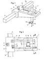
- the injection molding removal device 1 shown in FIG. 1 of the drawing has a guide bed 2 which, for example, is mounted on an injection molding machine parallel to the direction of actuation of the clamping unit for the injection mold.
- a slide can be moved along the guide bed 2, which in turn carries a cantilever arm 4 directed transversely to the guide bed 2.
- On the boom 4 is a Support 5 is arranged to be longitudinally movable, which holds a suspension link 6, which is arranged to be movable in support 5 in the upward and downward direction.
- an injection molding gripper 7 which is adjustable on the one hand about a vertical axis 8 relative to the hanging member 6, on the other hand can be pivoted relative to it about a horizontal axis 9 and can also be rotated about a longitudinal axis 10-10 .
- the injection molding removal device 1 according to FIG. 1 thus forms a manipulator, as it were, which has three linear movement coordinates and whose injection molding gripper 7 can also be displaced about three further joint axes.
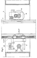
- An important structural design feature of the injection molding removal device 1 is that not only the drive 11 for the sliding movement of the slide 3 along the guide bed 2 and the drive 12 for the longitudinal movement of the support 5 on the boom 4 above the guide bed 2 sit on the slide 3 , but also the drive 13, by means of which the suspension link 6 can be raised and lowered in the vertical direction relative to the support 5.
- the drive 11 for the slide 3 interacts directly via a pinion 14 with a toothing 15 on the guide bed 2
- the drive 13 for the support 5 works on a belt or chain drive 20 which is installed in the longitudinal direction of the boom 4 and which also runs with his one drive strand is connected to the support 5.
- a spindle drive could also replace the belt or chain drive 20.
- the drive 13 for the suspension link 6 works on at least one shaft, which is mounted lying in the boom 4 parallel to its longitudinal direction.
- the shaft 16 works in the manner of a lead screw, that is to say over a driver extending over its entire length, with a transmission element 17 designed as a torque sleeve.
- This transmission element 17 is non-rotatably, but axially displaceable, in constant engagement with the shaft 16, its part rotatable relative to the support 5 carrying a pinion 18, which is in constant engagement with a rack 19 fastened to the hanging link 6 and extending in the longitudinal direction thereof.
- the shaft 16 not only forms a transmission means for generating the drive movement for the suspension link 6, but also a longitudinal guide for the support 5 on the boom 4.
- the suspension link 6 is formed from two telescopically displaceable longitudinal sections, the two shafts 16 and 16 'can work with the same direction of rotation. However, it would then make sense to choose the drive ratio between the second shaft 16 'and the lower telescopic part of the hanging link 6 to be larger, for example twice as large, as the ratio between the first shaft and the upper telescopic part of the hanging link 6. It would then namely created a differential drive for the hanging link 6, which would allow a faster lifting and lowering movement of the molding gripper 7.
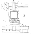
- suspension link 6 is expediently given a triple guide in the support 5.
- This is formed on the one hand by the rack 19, which cooperates with track disks 21 and 22 arranged on both sides of the pinion 18.
- two pairs of track rollers 23 'and 23 are rotatably mounted in the support 5, with which guide rods 24', 24" engage, which are in turn connected to the suspension link 6 by holding elements 25 along the entire length.
- the torque bushings used as transmission elements between the shafts 16 and 16 ', the support 5 and the suspension link 6 have a previously known type. With them, an obstacle-free axial displacement can be made possible by a ball seated in a longitudinal groove of the shaft and held in the sleeve, but the ball lying in the longitudinal groove when the shaft rotates Wave causes an entrainment effect for a part of the sleeve, which forms the pinion 18, which meshes with the rack 19 made of wear-resistant polyamide.
Landscapes
- Engineering & Computer Science (AREA)
- Robotics (AREA)
- Mechanical Engineering (AREA)
- Manufacturing & Machinery (AREA)
- Moulds For Moulding Plastics Or The Like (AREA)
- Injection Moulding Of Plastics Or The Like (AREA)
Applications Claiming Priority (2)
| Application Number | Priority Date | Filing Date | Title |
|---|---|---|---|
| DE3613074 | 1986-04-18 | ||
| DE19863613074 DE3613074A1 (de) | 1986-04-18 | 1986-04-18 | Spritzling-entnahmevorrichtung fuer spritzgiessmaschinen |
Publications (2)
| Publication Number | Publication Date |
|---|---|
| EP0241820A2 true EP0241820A2 (fr) | 1987-10-21 |
| EP0241820A3 EP0241820A3 (fr) | 1989-03-29 |
Family
ID=6298959
Family Applications (1)
| Application Number | Title | Priority Date | Filing Date |
|---|---|---|---|
| EP87104955A Withdrawn EP0241820A3 (fr) | 1986-04-18 | 1987-04-03 | Dispositif d'enlèvement de pièce injectée pour machines à mouler par injection |
Country Status (5)
| Country | Link |
|---|---|
| US (1) | US4732554A (fr) |
| EP (1) | EP0241820A3 (fr) |
| AU (1) | AU7119387A (fr) |
| BR (1) | BR8701812A (fr) |
| DE (1) | DE3613074A1 (fr) |
Cited By (3)
| Publication number | Priority date | Publication date | Assignee | Title |
|---|---|---|---|---|
| FR2639572A1 (fr) * | 1988-11-29 | 1990-06-01 | Renault | Robot multiaxes |
| CN104476740A (zh) * | 2014-11-12 | 2015-04-01 | 湖北荆硕自动化设备有限公司 | 多机械臂取出装置 |
| CN104669236A (zh) * | 2013-11-29 | 2015-06-03 | 徐建 | 侧取桁架三轴伺服机器人 |
Families Citing this family (28)
| Publication number | Priority date | Publication date | Assignee | Title |
|---|---|---|---|---|
| DE3830964A1 (de) * | 1988-09-12 | 1990-03-22 | Karl Hehl | Spritzgiessmaschine mit einer einrichtung zur entnahme der spritzteile aus dem spritzwerkzeug |
| US4867938B1 (en) * | 1988-01-29 | 1998-05-26 | Husky Injection Molding | Sequential injection molding process |
| US5185119A (en) * | 1988-01-29 | 1993-02-09 | Husky Injection Molding Systems Ltd. | Injection molding process |
| US5242014A (en) * | 1988-11-30 | 1993-09-07 | Nippon Steel Corporation | Continuous casting method and apparatus for implementing same method |
| US5372319A (en) * | 1989-10-03 | 1994-12-13 | Globe Products Inc. | Apparatus for loading and unloading workpieces |
| US5000654A (en) * | 1989-12-28 | 1991-03-19 | Star Seiki Co., Ltd. | Reciprocating drive apparatus for automatic molding removing machine |
| DE4017796C1 (fr) * | 1990-06-01 | 1991-12-19 | Richard 8057 Eching De Herbst | |
| US5139411A (en) * | 1991-04-01 | 1992-08-18 | Polacinski Michel C | Apparatus for reducing wear on mold ejection systems |
| US5354194A (en) * | 1993-01-28 | 1994-10-11 | Husky Injection Molding Systems Ltd. | High speed molded product retrieval device |
| US5513970A (en) * | 1993-05-10 | 1996-05-07 | Sony Corporation | Robot for ejection of an object from between two bodies |
| US6086808A (en) | 1997-08-19 | 2000-07-11 | Universal Ventures | Repositioning of articles between different positions within an intermittently accessible space |
| JP2979404B1 (ja) * | 1998-12-08 | 1999-11-15 | 株式会社ユーシン精機 | 射出成形品取出装置の制御方法及びこれを実施する射出成形品取出装置 |
| JP2001252954A (ja) * | 2000-03-13 | 2001-09-18 | Star Seiki Co Ltd | 成型品取出し機及び成型品取出し方法 |
| DE10234041B3 (de) * | 2002-07-26 | 2004-02-19 | Karl Hehl | Entnahmeeinrichtung für eine Kunststoff-Spritzgießmaschine |
| US20040084809A1 (en) * | 2002-11-05 | 2004-05-06 | Vanderploeg James A. | Side shuttle apparatus and method for an injection molding machine |
| NL1023776C2 (nl) * | 2003-06-30 | 2005-01-03 | Roboxis B V | Robot. |
| DE102004025416B4 (de) * | 2004-05-24 | 2013-01-17 | Siemens Aktiengesellschaft | Rechnergestütztes Ermittlungsverfahren für Zusatzlagesollwerte für ein lagegeführt verfahrbares Zusatzelement einer Maschine, insbesondere einer Produktionsmaschine |
| CN101306570B (zh) * | 2007-05-17 | 2011-01-05 | 鸿富锦精密工业(深圳)有限公司 | 模具装置 |
| US7708919B2 (en) * | 2008-05-08 | 2010-05-04 | Delphi Technologies, Inc. | Sprue removal in an injection molding machine |
| TW201119835A (en) * | 2009-12-10 | 2011-06-16 | Quanta Comp Inc | Pre-heat apparatus, injection molding with the same, and method of pre-heating injection molding |
| JP5781592B2 (ja) | 2010-04-01 | 2015-09-24 | アシィーナ オートメーション リミテッド | 統合された部品取扱装置を有する射出成形機械 |
| JP5764408B2 (ja) * | 2011-06-30 | 2015-08-19 | 株式会社ユーシン精機 | 成形品取出機 |
| CN104669238A (zh) * | 2013-11-29 | 2015-06-03 | 徐建 | 三轴高速伺服机器人的引拔梁 |
| CN104669239A (zh) * | 2013-11-29 | 2015-06-03 | 徐建 | 三轴桁架式高速伺服机器人 |
| JP6465615B2 (ja) * | 2014-10-22 | 2019-02-06 | 株式会社ユーシン精機 | 成形品取出機 |
| CN106142482B (zh) * | 2016-08-20 | 2018-01-02 | 河北工业大学 | 医用喉罩生产线喉罩自动摘取装置 |
| US11078016B2 (en) * | 2018-09-04 | 2021-08-03 | HanBin Kim | Mobile sorting systems |
| CN111633631B (zh) * | 2020-05-07 | 2021-08-06 | 邵东县环兴打火机制造有限公司 | 一种用于注塑的机械手 |
Family Cites Families (10)
| Publication number | Priority date | Publication date | Assignee | Title |
|---|---|---|---|---|
| US3665148A (en) * | 1971-04-07 | 1972-05-23 | Gen Motors Corp | Six-axis manipulator |
| US3760956A (en) * | 1971-08-23 | 1973-09-25 | Burch Controls Inc | Industrial robot |
| JPS6110968Y2 (fr) * | 1981-06-04 | 1986-04-08 | ||
| US4368018A (en) * | 1981-10-14 | 1983-01-11 | Husky Injection Molding Systems Inc. | Transporter for injection-molded parts or inserts therefor |
| DE3304641A1 (de) * | 1982-02-13 | 1983-09-15 | Hiroshi Teramachi | Waelzkoerpergelagerte laengsfuehrung fuer unbegrenzte schiebewege |
| SE430682B (sv) * | 1982-05-06 | 1983-12-05 | Asea Ab | Sett och anordning att tillfora och bortfora detaljer vid en robotbetjenad bearbetningsmaskin |
| US4571149A (en) * | 1983-04-14 | 1986-02-18 | Westinghouse Electric Corp. | General purpose orthogonal axes manipulator system |
| DE3420936C1 (de) * | 1984-06-05 | 1985-12-19 | Kuka Schweissanlagen + Roboter Gmbh, 8900 Augsburg | Schutzvorrichtung fuer die Fuehrungsbahn eines ersten Maschinenteiles,auf dem ein zweites Maschinenteil laengsbeweglich gelagert ist |
| US4571320A (en) * | 1984-10-31 | 1986-02-18 | General Motors Corporation | Method and apparatus for loading and unloading sheet molding compound in and from a press |
| DE8624943U1 (de) * | 1986-09-18 | 1986-10-30 | GMG-Gemminger Maschinenbau GmbH, 75050 Gemmingen | Teleskopartig ausfahrbare Handhabungs- oder Transporteinrichtung |
-
1986
- 1986-04-18 DE DE19863613074 patent/DE3613074A1/de not_active Withdrawn
-
1987
- 1987-04-03 EP EP87104955A patent/EP0241820A3/fr not_active Withdrawn
- 1987-04-08 AU AU71193/87A patent/AU7119387A/en not_active Abandoned
- 1987-04-15 BR BR8701812A patent/BR8701812A/pt unknown
- 1987-04-16 US US07/039,535 patent/US4732554A/en not_active Expired - Fee Related
Cited By (4)
| Publication number | Priority date | Publication date | Assignee | Title |
|---|---|---|---|---|
| FR2639572A1 (fr) * | 1988-11-29 | 1990-06-01 | Renault | Robot multiaxes |
| EP0371872A1 (fr) * | 1988-11-29 | 1990-06-06 | Regie Nationale Des Usines Renault | Robot multiaxes |
| CN104669236A (zh) * | 2013-11-29 | 2015-06-03 | 徐建 | 侧取桁架三轴伺服机器人 |
| CN104476740A (zh) * | 2014-11-12 | 2015-04-01 | 湖北荆硕自动化设备有限公司 | 多机械臂取出装置 |
Also Published As
| Publication number | Publication date |
|---|---|
| US4732554A (en) | 1988-03-22 |
| DE3613074A1 (de) | 1987-10-29 |
| AU7119387A (en) | 1987-10-22 |
| BR8701812A (pt) | 1988-01-26 |
| EP0241820A3 (fr) | 1989-03-29 |
Similar Documents
| Publication | Publication Date | Title |
|---|---|---|
| DE3613074A1 (de) | Spritzling-entnahmevorrichtung fuer spritzgiessmaschinen | |
| DE3303925C2 (de) | Massageeinrichtung | |
| EP0868964A1 (fr) | Dispositif réalisant un positionnement et une orientation bien defini d'au moins une platforme | |
| EP0395847A2 (fr) | Assemblage d'entraînement pour un toit pliant entraîné par moteur | |
| DE2800828A1 (de) | Vorrichtung zum wenden von werkstuecken | |
| DE1156728B (de) | Operationsleuchte | |
| DE3505836A1 (de) | Spritzgiessmaschine mit spritzling-entnahmevorrichtung | |
| DE2433954B2 (de) | Handhabungsgeraet | |
| DE102008029451B4 (de) | Vorrichtung zur automatischen Entnahme von Gegenständen aus Behältern | |
| DE69117297T2 (de) | Kupplung eines fussbodenkehrgerätes mit einem stangenähnlichen teil zum führen besagten gerätes | |
| CH656327A5 (de) | Schuettelmaschine. | |
| DE102013112802B4 (de) | Roboterarm mit flexiblem Zugelement | |
| DE1574639A1 (de) | Vorrichtung zum Einstellen der Lage eines in seiner Laengsrichtung bewegten Materialstreifens in bezug auf eine Bezugsebene | |
| DE3717957A1 (de) | Vorrichtung zum aufnehmen, transportieren, ablegen und/oder positionieren von werkstuecken | |
| DE3207177C2 (de) | Tisch mit einer in der Höhe und in der Neigung verstellbaren Tischplatte | |
| EP0132448B1 (fr) | Table à plateau réglable | |
| DE2331528A1 (de) | Kegelaufstellvorrichtung | |
| EP0792670A1 (fr) | Haie d'athlétisme | |
| EP0661014A2 (fr) | Dispositif pour la variation de la hauteur et/ou de l'inclinaison d'une surface de travail | |
| DE2500395A1 (de) | Vorrichtung zur einstellung der lage der schmalen seiten einer in ihrem querschnitt veraenderbaren stranggiesskokille | |
| DE4012645C1 (fr) | ||
| DE2155125C3 (de) | Hubvorrichtung einer Greiferbank einer selbsttätigen Hülsenwechseleinrichtung | |
| DE3515913C1 (de) | Waelzantrieb fuer eine Zahnradschleifmaschine | |
| DE2444412A1 (de) | Vorrichtung zum hin- und herbewegen einer spritzvorrichtung | |
| DE536352C (de) | Schraemvorrichtung |
Legal Events
| Date | Code | Title | Description |
|---|---|---|---|
| PUAI | Public reference made under article 153(3) epc to a published international application that has entered the european phase |
Free format text: ORIGINAL CODE: 0009012 |
|
| 17P | Request for examination filed |
Effective date: 19870424 |
|
| AK | Designated contracting states |
Kind code of ref document: A2 Designated state(s): AT CH DE FR GB IT LI |
|
| RAP1 | Party data changed (applicant data changed or rights of an application transferred) |
Owner name: BATTENFELD GMBH |
|
| PUAL | Search report despatched |
Free format text: ORIGINAL CODE: 0009013 |
|
| AK | Designated contracting states |
Kind code of ref document: A3 Designated state(s): AT CH DE FR GB IT LI |
|
| 17Q | First examination report despatched |
Effective date: 19900314 |
|
| STAA | Information on the status of an ep patent application or granted ep patent |
Free format text: STATUS: THE APPLICATION HAS BEEN WITHDRAWN |
|
| 18W | Application withdrawn |
Withdrawal date: 19910327 |
|
| R18W | Application withdrawn (corrected) |
Effective date: 19910327 |
|
| RIN1 | Information on inventor provided before grant (corrected) |
Inventor name: HELLMANN, DIETER |