EP0243023B1 - Câble pour ligne de transmission - Google Patents
Câble pour ligne de transmission Download PDFInfo
- Publication number
- EP0243023B1 EP0243023B1 EP87302894A EP87302894A EP0243023B1 EP 0243023 B1 EP0243023 B1 EP 0243023B1 EP 87302894 A EP87302894 A EP 87302894A EP 87302894 A EP87302894 A EP 87302894A EP 0243023 B1 EP0243023 B1 EP 0243023B1
- Authority
- EP
- European Patent Office
- Prior art keywords
- primary conductor
- wrapped
- diameter
- wire
- transmission wire
- Prior art date
- Legal status (The legal status is an assumption and is not a legal conclusion. Google has not performed a legal analysis and makes no representation as to the accuracy of the status listed.)
- Expired - Lifetime
Links
- 230000005540 biological transmission Effects 0.000 title claims abstract description 15
- 239000004020 conductor Substances 0.000 claims abstract description 59
- 229910052782 aluminium Inorganic materials 0.000 claims description 7
- XAGFODPZIPBFFR-UHFFFAOYSA-N aluminium Chemical group [Al] XAGFODPZIPBFFR-UHFFFAOYSA-N 0.000 claims description 7
- 229920006267 polyester film Polymers 0.000 claims description 5
- 239000000463 material Substances 0.000 claims description 3
- 229920001721 polyimide Polymers 0.000 claims description 3
- 239000004810 polytetrafluoroethylene Substances 0.000 claims 1
- 229920001343 polytetrafluoroethylene Polymers 0.000 claims 1
- 239000011888 foil Substances 0.000 abstract description 35
- 239000000758 substrate Substances 0.000 abstract description 3
- 238000009413 insulation Methods 0.000 description 18
- 229910052751 metal Inorganic materials 0.000 description 12
- 239000002184 metal Substances 0.000 description 12
- 239000004642 Polyimide Substances 0.000 description 2
- 238000005516 engineering process Methods 0.000 description 2
- 208000027418 Wounds and injury Diseases 0.000 description 1
- 238000005299 abrasion Methods 0.000 description 1
- 239000011248 coating agent Substances 0.000 description 1
- 238000000576 coating method Methods 0.000 description 1
- 230000006378 damage Effects 0.000 description 1
- 230000000694 effects Effects 0.000 description 1
- 229920000295 expanded polytetrafluoroethylene Polymers 0.000 description 1
- 238000001125 extrusion Methods 0.000 description 1
- 208000014674 injury Diseases 0.000 description 1
- 238000000034 method Methods 0.000 description 1
- 229920003055 poly(ester-imide) Polymers 0.000 description 1
- 230000001681 protective effect Effects 0.000 description 1
- 238000010618 wire wrap Methods 0.000 description 1
Images

Classifications
-
- H—ELECTRICITY
- H01—ELECTRIC ELEMENTS
- H01B—CABLES; CONDUCTORS; INSULATORS; SELECTION OF MATERIALS FOR THEIR CONDUCTIVE, INSULATING OR DIELECTRIC PROPERTIES
- H01B11/00—Communication cables or conductors
- H01B11/02—Cables with twisted pairs or quads
- H01B11/12—Arrangements for exhibiting specific transmission characteristics
-
- H—ELECTRICITY
- H01—ELECTRIC ELEMENTS
- H01B—CABLES; CONDUCTORS; INSULATORS; SELECTION OF MATERIALS FOR THEIR CONDUCTIVE, INSULATING OR DIELECTRIC PROPERTIES
- H01B7/00—Insulated conductors or cables characterised by their form
- H01B7/0009—Details relating to the conductive cores
Definitions
- This invention relates to an electric transmission wire including a primary conductor wherein the characteristic impedance along the length of the wire is low, yet the wire is capable of being terminated using standard termination equipment.
- This invention is particularly useful for solderless wrap connections to printed circuit boards or panels and for twisted wire and single wire interconnections.
- transmission wire with a low impedance (less than 100 ohms) was not available for use with standard termination equipment.
- a primary conductor with a diameter greater than 0.508mm had to be selected in order to achieve a low characteristic impedance. Only a thin wall of insulation could be wrapped around the primary conductor without increasing the characteristic impedance. Since only a thin wall of insulation could be used, there was a poor cut-through resistance of this outer wall of insulation and there were other stripping difficulties.
- GB-A-1151842 discloses a conductor wrapped with a low resistivity tape.
- the purpose of the tape is to attenuate high frequency currents and no insulating layer is required.
- the effect of the tape on the characteristic impedance of the cable would be negligible.
- an electric transmission wire comprising a primary conductor with a diameter of less than 20 mils (0.508mm) wrapped with at least one layer of material characterised in that the material of the at least one layer comprises a conductive layer in continuous contact with the primary conductor, said primary conductor and wrapped conductive layer further wrapped with at least one layer of an insulating film such that the overall transmission wire maintains a characteristic impedance below 100 ohms.
- the layer of conductive material which can be conductive foil or a conductive foil laminated to a substrate layer, is in contact with the primary conductor, the effective electrical diameter of the primary conductor is increased.
- An outer layer of insulation may be applied over the foil and primary conductor.
- the foil or foil laminate may be applied by either spiral wrapping or by longitudinal wrapping around the primary conductor. This invention provides a desired characteristic impedance along the length of the wire and allows easy removal for standard termination and increased cut-through resistance.
- the effective electrical diameter of a primary conductor of less than 0.508mm diameter is increased by wrapping conductive foil, or conductive foil laminated to a substrate on to the primary conductor, the foil being in contact with the conductor. This may be accomplished by conventional wire wrapping techniques and equipment.
- the primary conductor with conductive foil or laminate in contact with it is able to maintain a low characteristic impedance and still be compatible with standard termination equipment and printed circuit boards.
- a thicker layer of outer insulation may be applied over the wrapped primary conductor and will not affect the characteristic impedance. This provides increased cut-through resistance. Conventional stripping equipment may be used with the wrapped wire and the thicker layer of outer insulation is easily removed for termination.
- the invention also provides benefits for applications in state of the art electronic equipment.
- the primary conductor with a diameter of less than 0.508mm is compatible with terminal and grid spacings of a printed circuit board having 0.16 cm2 terminal with grid spacing of 0.254cm.
- An inventive embodiment may be used either as a single insulated wire or two insulated wires may be twisted together and be used as a pair of twisted wires.
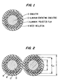
- a conductive metal foil laminate consisting of a metal foil coating 2 on a laminar support 1 is spirally wrapped around a primary conductor 3 with the metal foil 2 facing into and in continuous contact with the primary conductor 3 and making electrical contact between the primary conductor 3 and foil 2.
- the preferred metal foil laminate comprises aluminum foil bonded to polyester or polyimide base film 1 or aluminum foil bonded to a film of expanded polytetrafluoroethylene 1.
- the primary conductor 3 may have a single wrapping of metal foil or it may have a plurality of wrappings, depending on the desired thickness of the wall, as depicted in Figure 1. Additional insulation 4, if required, is applied over the top of the metal foil laminate wrapping.
- Figure 2 shows a cross-sectional view of a twisted pair of insulated wires in which a conductive metal foil laminate, consisting of metal foil 12 on a laminar support 10, is spirally wrapped around each primary conductor 13 with the metal foil 12 facing the wires and in continuous contact with primary conductors 13 making electrical contact between the primary conductors 13 and the foil 12. Additional insulation 14, if required, is applied over the top of the metal foil laminate wrapping.
- a conductive metal foil laminate consisting of metal foil 12 on a laminar support 10
- Figure 2 also shows the initial diameter of the primary conductor 13 as being d1.
- the effective electrical diameter is increased and is measured as d eff .
- the primary conductor actual diameter d1 is also its effective electrical diameter.
- Additional insulation 14 may be applied over the top of the metal foil laminate wrapping.
- the total diameter of the conductor 13, wrapped conductive foil 12, support 10 and outer insulation covering 14 is measured as D.
- the characteristic impedance Z is logarithmically related to the diameter of the insulated wire by the ratio D/d. Where the invention is used, the diameter of the primary conductor (d) is substituted by d eff . Thus, by using the invention, the characteristic impedance is reduced because the effective electrical diameter of the primary conductor is increased.
- the additional insulation 14 may be a polyester film or polyimide based film insulation. This additional insulation may be applied by extrusion or by additional wrapping to a desired outside diameter. Cut-through resistance is increased by the addition of this insulation.
- a single 28(l) AWG primary conductor of actual diameter 0.32mm was wrapped with three layers of aluminum foil laminated tape whereby the foil was in constant physical contact with the primary conductor.
- An outer layer of polyester film insulation was applied over the primary conductor foil combination.
- the final diameter of this embodiment was 19.6 mils 0.498mm.
- the diameter of the primary conductor of 0.32mm was increased to an effective electrical diameter of 0.445mm.
- the characteristic impedance was maintained at 50 ohms and the resulting wire had a calculated D/d ratio of 1.13.
- An insulated wire with an outer wall thickness of 0.019mm does not fit standard automated stripping machines.
- the standard wire cutting equipment is not able to cut into, grab and pull off the outer wrapping without injury to the primary conductor. Further, a radius of curvature of 0.179mm does not meet conventional wire cut-through requirements.
- the present invention provides a primary conductor with an increased electrical diameter and increased outer wall diameter and cut-through radius of curvature so that standard automated stripping machines could be used.
- Test data was accumulated and calculations made were similar to those as described in Example 1. Test results are summarised in Chart 2 shown below.
- the inventive entity allows the impedance to remain at 55 ohms but the outer wall and cut-through radius are increased (by 39%) and can be used with existing wire stripping equipment.
- a pair of 30(l) AWG primary conductors are individually wrapped with aluminum foil laminated tape so that the foil is in constant physical contact with each primary conductor.
- the outer diameter D is 0.495mm
- the effective electrical diameter d eff is 0.366mm
- the ratio of D/d eff is found to be 1.31.
- the wall thickness has been increased to add cut-through resistance without increasing the characteristic impedance in this invention. Further, the cut-through radius of curvature is increased by 43% and is easily compatible with existing stripping equipment.
Landscapes
- Communication Cables (AREA)
- Detergent Compositions (AREA)
- Non-Insulated Conductors (AREA)
- Insulated Conductors (AREA)
- Organic Low-Molecular-Weight Compounds And Preparation Thereof (AREA)
- Addition Polymer Or Copolymer, Post-Treatments, Or Chemical Modifications (AREA)
- Laying Of Electric Cables Or Lines Outside (AREA)
- Vehicle Body Suspensions (AREA)
- Near-Field Transmission Systems (AREA)
- Acyclic And Carbocyclic Compounds In Medicinal Compositions (AREA)
Claims (8)
- Fil de transmission électrique comprenant un conducteur primaire (3) ayant un diamètre inférieur à 0,508 mm enveloppé d'au moins une couche (2), caractérisé en ce que la matière de ladite couche au moins comprend une couche conductrice qui est en contact continu avec le conducteur primaire, le conducteur primaire et la couche conductrice enveloppée étant en outre enveloppés d'au moins une couche d'un film isolant (4) afin que le fil de transmission dans son ensemble garde une impédance caractéristique inférieure à 100 Ω.
- Fil de transmission électrique selon la revendication 1, caractérisé en ce qu'il est retordu avec un second conducteur primaire ayant un diamètre inférieur à 0,508 mm enveloppé d'une couche conductrice en contact continu avec lui et enveloppé en outre d'au moins une couche d'un film isolant.
- Fil de transmission électrique selon la revendication 1, caractérisé en ce que le fil garde une impédance caractéristique inférieure à 75 Ω.
- Fil de transmission électrique selon la revendication 1, caractérisé en ce que la couche ou chaque couche conductrice enveloppée est formée d'un stratifié d'aluminium sur un film de polyester.
- Fil de transmission électrique selon la revendication 1, caractérisé en ce que la couche ou chaque couche conductrice enveloppée est formée d'un stratifié d'aluminium sur un film de PTFE expansé.
- Fil de transmission électrique selon la revendication 1, caractérisé en ce que la couche ou chaque couche conductrice enveloppée est un stratifié d'aluminium sur un film de polyimide.
- Fil de transmission électrique selon la revendication 1, caractérisé en ce que la couche ou chaque couche conductrice enveloppée est enroulée en spirale autour du conducteur primaire.
- Fil de transmission électrique selon la revendication 1, caractérisé en ce que la couche ou chaque couche conductrice enveloppée est enroulée longitudinalement autour du conducteur primaire.
Priority Applications (1)
| Application Number | Priority Date | Filing Date | Title |
|---|---|---|---|
| AT87302894T ATE73256T1 (de) | 1986-04-07 | 1987-04-02 | Kabel fuer transmissionsleitung. |
Applications Claiming Priority (2)
| Application Number | Priority Date | Filing Date | Title |
|---|---|---|---|
| US84888186A | 1986-04-07 | 1986-04-07 | |
| US848881 | 1986-04-07 |
Publications (3)
| Publication Number | Publication Date |
|---|---|
| EP0243023A2 EP0243023A2 (fr) | 1987-10-28 |
| EP0243023A3 EP0243023A3 (en) | 1988-07-20 |
| EP0243023B1 true EP0243023B1 (fr) | 1992-03-04 |
Family
ID=25304532
Family Applications (1)
| Application Number | Title | Priority Date | Filing Date |
|---|---|---|---|
| EP87302894A Expired - Lifetime EP0243023B1 (fr) | 1986-04-07 | 1987-04-02 | Câble pour ligne de transmission |
Country Status (12)
| Country | Link |
|---|---|
| EP (1) | EP0243023B1 (fr) |
| JP (1) | JPS63119112A (fr) |
| AT (1) | ATE73256T1 (fr) |
| AU (1) | AU7052487A (fr) |
| CA (1) | CA1277731C (fr) |
| DE (1) | DE3776949D1 (fr) |
| DK (1) | DK177887A (fr) |
| FI (1) | FI871483A7 (fr) |
| GB (1) | GB2188768B (fr) |
| NO (1) | NO871432L (fr) |
| PT (1) | PT84630B (fr) |
| ZA (1) | ZA872487B (fr) |
Families Citing this family (1)
| Publication number | Priority date | Publication date | Assignee | Title |
|---|---|---|---|---|
| JPH074411A (ja) * | 1993-06-16 | 1995-01-10 | Toyoda Gosei Co Ltd | 合成樹脂製ファスナー |
Family Cites Families (4)
| Publication number | Priority date | Publication date | Assignee | Title |
|---|---|---|---|---|
| GB1151842A (en) * | 1966-01-12 | 1969-05-14 | Donald Francis Binns | Improvements in Electrical Conductors. |
| US3412199A (en) * | 1967-01-12 | 1968-11-19 | Research Corp | Electric power transmission cable |
| JPS6011401B2 (ja) * | 1977-02-09 | 1985-03-26 | 松下電器産業株式会社 | 銅箔糸線 |
| US4414428A (en) * | 1979-05-29 | 1983-11-08 | Teledyne Industries, Inc. | Expanded metal containing wires and filaments |
-
1987
- 1987-03-23 AU AU70524/87A patent/AU7052487A/en not_active Abandoned
- 1987-04-02 JP JP62082148A patent/JPS63119112A/ja active Granted
- 1987-04-02 DE DE8787302894T patent/DE3776949D1/de not_active Expired - Fee Related
- 1987-04-02 AT AT87302894T patent/ATE73256T1/de not_active IP Right Cessation
- 1987-04-02 GB GB8707921A patent/GB2188768B/en not_active Expired - Fee Related
- 1987-04-02 EP EP87302894A patent/EP0243023B1/fr not_active Expired - Lifetime
- 1987-04-06 FI FI871483A patent/FI871483A7/fi not_active IP Right Cessation
- 1987-04-06 CA CA000533900A patent/CA1277731C/fr not_active Expired - Fee Related
- 1987-04-06 NO NO871432A patent/NO871432L/no unknown
- 1987-04-07 PT PT84630A patent/PT84630B/pt not_active IP Right Cessation
- 1987-04-07 DK DK177887A patent/DK177887A/da not_active Application Discontinuation
- 1987-04-07 ZA ZA872487A patent/ZA872487B/xx unknown
Also Published As
| Publication number | Publication date |
|---|---|
| DK177887A (da) | 1987-10-08 |
| JPS63119112A (ja) | 1988-05-23 |
| EP0243023A2 (fr) | 1987-10-28 |
| GB2188768B (en) | 1990-01-24 |
| AU7052487A (en) | 1987-10-08 |
| DE3776949D1 (de) | 1992-04-09 |
| FI871483L (fi) | 1987-10-08 |
| JPH0456408B2 (fr) | 1992-09-08 |
| CA1277731C (fr) | 1990-12-11 |
| GB8707921D0 (en) | 1987-05-07 |
| GB2188768A (en) | 1987-10-07 |
| FI871483A0 (fi) | 1987-04-06 |
| DK177887D0 (da) | 1987-04-07 |
| ZA872487B (en) | 1988-03-30 |
| PT84630B (pt) | 1989-11-30 |
| PT84630A (fr) | 1987-05-01 |
| ATE73256T1 (de) | 1992-03-15 |
| NO871432D0 (no) | 1987-04-06 |
| EP0243023A3 (en) | 1988-07-20 |
| NO871432L (no) | 1987-10-08 |
| FI871483A7 (fi) | 1987-10-08 |
Similar Documents
| Publication | Publication Date | Title |
|---|---|---|
| KR920009848B1 (ko) | 시일드가 붙어있는 플랫케이블 | |
| US6486395B1 (en) | Interlocked metal-clad cable | |
| US5107076A (en) | Easy strip composite dielectric coaxial signal cable | |
| US4754102A (en) | Directional interconnection cable for high fidelity signal transmission | |
| US5283390A (en) | Twisted pair data bus cable | |
| US5142100A (en) | Transmission line with fluid-permeable jacket | |
| US4847448A (en) | Coaxial cable | |
| WO1990012407A1 (fr) | Construction de câbles electriques coaxiaux | |
| US6148510A (en) | Method for producing terminal wire connection | |
| US5262589A (en) | High velocity propagation ribbon cable | |
| US4943688A (en) | Ribbon coaxial cable with offset drain wires | |
| US4808773A (en) | Low impedance cable | |
| CA2051505C (fr) | Cable electrique a grande impedance et methode de formage | |
| EP0243023B1 (fr) | Câble pour ligne de transmission | |
| EP0784327A1 (fr) | Câble pour ligne de transmission | |
| US4769515A (en) | Primary transmission line cable | |
| CN215600107U (zh) | 一种特性阻抗能保持连续性的平行对电缆 | |
| JP3280772B2 (ja) | 電磁波遮蔽ケーブル | |
| JP3639133B2 (ja) | 高速細線同軸ケーブル及び高速細線フラット同軸ケーブル | |
| JPH0896631A (ja) | 多対シールドケーブル | |
| JP2512961Y2 (ja) | 低静電容量ケ―ブル | |
| CN219017278U (zh) | 一种数据传输线 | |
| EP0296692A2 (fr) | Câble électrique multiconducteur à performance électrique contrôlée | |
| JPS626291B2 (fr) | ||
| JP2501881Y2 (ja) | 多心ケ―ブル |
Legal Events
| Date | Code | Title | Description |
|---|---|---|---|
| PUAI | Public reference made under article 153(3) epc to a published international application that has entered the european phase |
Free format text: ORIGINAL CODE: 0009012 |
|
| AK | Designated contracting states |
Kind code of ref document: A2 Designated state(s): AT BE CH DE ES FR GB GR IT LI LU NL SE |
|
| RHK1 | Main classification (correction) |
Ipc: H01B 11/12 |
|
| PUAL | Search report despatched |
Free format text: ORIGINAL CODE: 0009013 |
|
| AK | Designated contracting states |
Kind code of ref document: A3 Designated state(s): AT BE CH DE ES FR GB GR IT LI LU NL SE |
|
| 17P | Request for examination filed |
Effective date: 19880519 |
|
| 17Q | First examination report despatched |
Effective date: 19910507 |
|
| GRAA | (expected) grant |
Free format text: ORIGINAL CODE: 0009210 |
|
| AK | Designated contracting states |
Kind code of ref document: B1 Designated state(s): AT BE CH DE ES FR GB GR IT LI LU NL SE |
|
| PG25 | Lapsed in a contracting state [announced via postgrant information from national office to epo] |
Ref country code: NL Effective date: 19920304 Ref country code: LI Effective date: 19920304 Ref country code: GR Free format text: LAPSE BECAUSE OF FAILURE TO SUBMIT A TRANSLATION OF THE DESCRIPTION OR TO PAY THE FEE WITHIN THE PRESCRIBED TIME-LIMIT Effective date: 19920304 Ref country code: CH Effective date: 19920304 Ref country code: BE Effective date: 19920304 Ref country code: AT Effective date: 19920304 |
|
| REF | Corresponds to: |
Ref document number: 73256 Country of ref document: AT Date of ref document: 19920315 Kind code of ref document: T |
|
| REF | Corresponds to: |
Ref document number: 3776949 Country of ref document: DE Date of ref document: 19920409 |
|
| ITTA | It: last paid annual fee | ||
| PGFP | Annual fee paid to national office [announced via postgrant information from national office to epo] |
Ref country code: NL Payment date: 19920430 Year of fee payment: 6 |
|
| PGFP | Annual fee paid to national office [announced via postgrant information from national office to epo] |
Ref country code: AT Payment date: 19920519 Year of fee payment: 6 |
|
| PGFP | Annual fee paid to national office [announced via postgrant information from national office to epo] |
Ref country code: LU Payment date: 19920520 Year of fee payment: 6 |
|
| ET | Fr: translation filed | ||
| ITF | It: translation for a ep patent filed | ||
| PGFP | Annual fee paid to national office [announced via postgrant information from national office to epo] |
Ref country code: ES Payment date: 19920611 Year of fee payment: 6 |
|
| PG25 | Lapsed in a contracting state [announced via postgrant information from national office to epo] |
Ref country code: ES Free format text: LAPSE BECAUSE OF FAILURE TO SUBMIT A TRANSLATION OF THE DESCRIPTION OR TO PAY THE FEE WITHIN THE PRESCRIBED TIME-LIMIT Effective date: 19920615 |
|
| REG | Reference to a national code |
Ref country code: CH Ref legal event code: PL |
|
| NLV1 | Nl: lapsed or annulled due to failure to fulfill the requirements of art. 29p and 29m of the patents act | ||
| EPTA | Lu: last paid annual fee | ||
| PLBE | No opposition filed within time limit |
Free format text: ORIGINAL CODE: 0009261 |
|
| STAA | Information on the status of an ep patent application or granted ep patent |
Free format text: STATUS: NO OPPOSITION FILED WITHIN TIME LIMIT |
|
| 26N | No opposition filed | ||
| PG25 | Lapsed in a contracting state [announced via postgrant information from national office to epo] |
Ref country code: LU Free format text: LAPSE BECAUSE OF NON-PAYMENT OF DUE FEES Effective date: 19930402 |
|
| EAL | Se: european patent in force in sweden |
Ref document number: 87302894.8 |
|
| PGFP | Annual fee paid to national office [announced via postgrant information from national office to epo] |
Ref country code: FR Payment date: 19990317 Year of fee payment: 13 |
|
| PGFP | Annual fee paid to national office [announced via postgrant information from national office to epo] |
Ref country code: SE Payment date: 19990318 Year of fee payment: 13 Ref country code: GB Payment date: 19990318 Year of fee payment: 13 Ref country code: DE Payment date: 19990318 Year of fee payment: 13 |
|
| PG25 | Lapsed in a contracting state [announced via postgrant information from national office to epo] |
Ref country code: GB Free format text: LAPSE BECAUSE OF NON-PAYMENT OF DUE FEES Effective date: 20000402 |
|
| PG25 | Lapsed in a contracting state [announced via postgrant information from national office to epo] |
Ref country code: SE Free format text: LAPSE BECAUSE OF NON-PAYMENT OF DUE FEES Effective date: 20000403 |
|
| GBPC | Gb: european patent ceased through non-payment of renewal fee |
Effective date: 20000402 |
|
| EUG | Se: european patent has lapsed |
Ref document number: 87302894.8 |
|
| PG25 | Lapsed in a contracting state [announced via postgrant information from national office to epo] |
Ref country code: FR Free format text: LAPSE BECAUSE OF NON-PAYMENT OF DUE FEES Effective date: 20001229 |
|
| PG25 | Lapsed in a contracting state [announced via postgrant information from national office to epo] |
Ref country code: DE Free format text: LAPSE BECAUSE OF NON-PAYMENT OF DUE FEES Effective date: 20010201 |
|
| REG | Reference to a national code |
Ref country code: FR Ref legal event code: ST |
|
| PG25 | Lapsed in a contracting state [announced via postgrant information from national office to epo] |
Ref country code: IT Free format text: LAPSE BECAUSE OF NON-PAYMENT OF DUE FEES;WARNING: LAPSES OF ITALIAN PATENTS WITH EFFECTIVE DATE BEFORE 2007 MAY HAVE OCCURRED AT ANY TIME BEFORE 2007. THE CORRECT EFFECTIVE DATE MAY BE DIFFERENT FROM THE ONE RECORDED. Effective date: 20050402 |