EP0243064B1 - Système de pesage combinatoire - Google Patents
Système de pesage combinatoire Download PDFInfo
- Publication number
- EP0243064B1 EP0243064B1 EP87303215A EP87303215A EP0243064B1 EP 0243064 B1 EP0243064 B1 EP 0243064B1 EP 87303215 A EP87303215 A EP 87303215A EP 87303215 A EP87303215 A EP 87303215A EP 0243064 B1 EP0243064 B1 EP 0243064B1
- Authority
- EP
- European Patent Office
- Prior art keywords
- article
- hopper
- article batch
- weigh
- handling units
- Prior art date
- Legal status (The legal status is an assumption and is not a legal conclusion. Google has not performed a legal analysis and makes no representation as to the accuracy of the status listed.)
- Expired
Links
- 238000005303 weighing Methods 0.000 title claims description 38
- 238000007599 discharging Methods 0.000 claims description 7
- 230000007246 mechanism Effects 0.000 description 7
- 238000004806 packaging method and process Methods 0.000 description 3
- 230000003466 anti-cipated effect Effects 0.000 description 1
- 230000015572 biosynthetic process Effects 0.000 description 1
- 239000013307 optical fiber Substances 0.000 description 1
- 125000006850 spacer group Chemical group 0.000 description 1
Images



Classifications
-
- G—PHYSICS
- G01—MEASURING; TESTING
- G01G—WEIGHING
- G01G13/00—Weighing apparatus with automatic feed or discharge for weighing-out batches of material
- G01G13/16—Means for automatically discharging weigh receptacles under control of the weighing mechanism
- G01G13/18—Means for automatically discharging weigh receptacles under control of the weighing mechanism by valves or flaps in the container bottom
-
- G—PHYSICS
- G01—MEASURING; TESTING
- G01G—WEIGHING
- G01G19/00—Weighing apparatus or methods adapted for special purposes not provided for in the preceding groups
- G01G19/387—Weighing apparatus or methods adapted for special purposes not provided for in the preceding groups for combinatorial weighing, i.e. selecting a combination of articles whose total weight or number is closest to a desired value
- G01G19/393—Weighing apparatus or methods adapted for special purposes not provided for in the preceding groups for combinatorial weighing, i.e. selecting a combination of articles whose total weight or number is closest to a desired value using two or more weighing units
Definitions
- This invention relates to a combinational weighing system.
- combinational weighing is meant weighing articles by a plurality of weighing devices, performing arithmetic operations for combinations of measured weight values and then selecting a combination according to a predetermined criterion.
- the major features of combinational weighing are great accuracy and high throughput.
- Electronic control units for such combinational weighing systems have been disclosed, for example, in US-A-4 396 078.
- Systems with weighing devices arranged radially in a circular formation around an article distributing table have been disclosed for example, in US-A-4 398 612, US-A-4 520 884, US-A-4 535 055, US-A-4 544 042, JP-A-6 085 332.
- EP-A-0 114 745 there is disclosed a combinational weighing system as mentioned above comprising pool hoppers below each of which are arranged two weigh hoppers. To discharge an article batch each pool hopper is provided with two gates through which article batches are alternately discharged into respective weigh hoppers without moving the pool hopper.
- a combinational weighing system comprising a weigher structure defining a longitudinal direction and a transverse direction, said weigher structure including a plurality of article batch handling units disposed linearly in said transverse direction in a mutually adjacent relationship; an article feeding means for accepting articles to be weighed and feeding article batches individually to said article batch handling units; and a discharging means disposed below said article batch handling units to receive batches discharged from said article batch handling units, each of said article batch handling units comprising a pool hopper with two gates for receiving an article batch from said article feeding means and discharging said received article batch by opening one of said two gates, and two weigh hoppers disposed below said pool hopper adjacent to each other in said longitudinal direction respectively for receiving said article batch discharged from said pool hopper through one of said two gates, weighing said received article batch, outputting a weight signal indicative of the weight of said article batch, and discharging said weighed article batch by opening a gate of the weigh hopper in which the batch is contained.
- each pool hopper has a single spring means serving to maintain said two gates in closed positions and two rotary solenoids disposed one above the other and each serving to cause a respective one of said gates to open against the force of said spring means in response to a hopper operating signal transmitted from a remote controller through a cable means which connects said weigher structure and said remote controller and serves to transmit signals therebetween, said weigher structure further including a driving unit and a driving-and-weighing unit sandwiching said article batch handling units therebetween, said driving unit having therein said rotary solenoids for said pool hopper, each of said article batch handling units including a first weigh hopper gate operating rotary solenoid and a second weigh hopper gate operating rotary solenoid, said first weigh hopper gate operating rotary solenoid being contained in said driving unit below said rotary solenoids for said pool hopper gates, and said second weigh hopper gate operating rotary solenoid being disposed inside said driving-and-weighing unit.
- the present invention provides a compact combinational weighing system without sacrificing the generally anticipated features of combinational weighing related to speed and accuracy.
- the system to be described is a combinational weighing system with fourteen weighing devices and comprises a structure (to be referred to as a weigher structure hereinbelow) which houses these weighing devices, and a separate remote control unit which contains electrical circuits for controlling the operation of the entire system.
- the weigher structure and the remote control unit are connected by a flexible cable so that signals can be exchanged between them but they can be physically set apart by up to 10 meters.
- the weigher structure 10 is shaped nearly like a square box with the maximum external dimensions of about 580 mm in length; about 565 mm in width and about 610 mm in height, exclusive of means such as conveyor belt for delivering articles to be weighed and a packaging unit into which weighed articles are discharged.
- a transversely elongate inlet hopper 11 is placed at the top section of the weigher structure 10 for receiving articles to be weighed from an article supply means such as a conveyor belt (not shown).
- the inlet hopper 11 has seven outlets at the bottom through which the articles delivered thereto will slide into seven troughs 12 which are longitudinally elongate, having an article receiving end and an article delivering end, and are parallel to each other in one-to- one relationships with the seven outlets of the inlet hopper 11 and the seven article batch handling units.
- Each trough 12 is supported from below by its own vibrator 13 such that articles delivered to its article receiving end are transported to the article delivery end by the vibratory motion of the trough 12 caused by the vibrator 13 and are delivered to the article batch handling unit corresponding to that trough 12.
- Each article batch handling unit includes a pool hopper 15 and two weigh hoppers 16.
- the pool hopper 15 serves to receive an article batch from the trough 12 corresponding to the article batch handling unit to which it belongs and to selectively discharge the article batch into one of the weigh hoppers 16 disposed therebelow.
- the pool hopper 15 is generally below the article delivering end of the corresponding trough 12 and is provided with two gates at the bottom as will be described more in detail below.
- the two weigh hoppers 16 are disposed below the corresponding pool hopper 15 and longitudinally adjacent to each other. Each weigh hopper 16 serves not only to receive an article batch from the pool hopper 15 disposed thereabove but also to weigh and discharge the received article batch.
- the two weigh hoppers in each article batch handling unit will be referred to as the front weigh hopper 16a and the back weigh hopper 16b, respectively, as shown in Fig. 1, the back weigh hopper 16b being on the side closer to the inlet hopper 11.
- Numeral 16 will be used where reference is made generally to both or either of the weigh hoppers 16a and 16b.
- Numeral 17 indicates a funnel-shaped discharge chute disposed below the array of weigh hoppers 16 and at the bottom of the weigher structure 10. It serves to receive article batches discharged from the weigh hoppers 16 and further to discharge them together into a packaging unit or the like (not shown) which is typically used in combination with the weighing system.
- Numeral 19 indicates a driver unit containing devices for opening hopper gates as will be explained below.
- Numeral 20 indicates an optical fiber cable which may be as long as 10 meters and connects to the remote control unit (not shown in Figs. 1 and 2) for exchanging various signals for the operation of the system.
- Numeral 21 indicates a driving-and-weighing unit containing both hopper gate driving devices and weighing devices for measuring the weights of article batches in weigh hoppers 16.
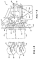
- Fig. 3 shows the structure of an individual pool hopper 15 inclusive of parts for opening its gates.
- the pool hopper 15 is of a double-gate type.
- These gates will be referred to as the front gate 25a and the back gate 25b as shown in Fig. 3 for the sake of convenience and are adapted to swing open and close in the longitudinal direction.
- the front gate 25a is adapted to rotate around a horizontally fixed pivot 27 and is attached to an L-shaped member 28.
- the back gate 25b is adapted to rotate around another horizontally fixed pivot 31 and is attached to a connecting member 32.
- Another L-shaped member 34 is directly above the first L-shaped member 28 and is rotatably supported by still another horizontally fixed pivot 36.
- a straight linking piece 37 is rotatably connected through pins 38 and 39 respectively to one end of the connecting member 32 and to one end of the L-shaped member 34 to complete a linking mechanism.
- a spring 40 connects one end of the L-shaped member 28 and the end of the connecting member 32 distal to the pin 38 so as to keep the gate 25 closed by its compressive force.
- the pool hopper 15 is supported as a whole by a horizontal hanger bar 42 secured by supporting means to a vertical wall 44 of the driving unit 19.
- rotary solenoids 45 for opening the pool hopper gates 25 are provided inside the driver unit 19.
- Each of these rotary solenoids 45 has a radially extending arm 47 affixed to its axis 48.
- a roller is rotatably attached at the end of the arm 47 distal to the axis 48 such that, if the arm 47 is caused to rotate around the axis 48, the roller 49 will push the free end of the L-shaped member 28 or 34 in the upward direction. If the L-shaped member 28 is thus rotated in the clockwise direction (with reference to Fig. 3) around the pivot 27, this causes the front gate 25a to open by stretching the spring 40 to the left.
- Fig. 4 is a view taken along the line 4 - 4 of Fig. 3 to show the positional relationships among the arms 47 and the stoppers 50. The positions of the arms 47 when the gates 25 are opened (one at a time) are delineated by dotted lines.
- Fig. 5 being a side view of one of the weigh hoppers 16
- Fig. 6 being an enlarged, more detailed view of a portion of Fig. 1 including the weigh hoppers 16.
- the weigh hoppers 16 are of a single-gate structure.
- the relative directions in which hopper gates open are generally a matter of design choice if the hoppers are significantly far apart and there is no need to consider the possibilities of interference among the gates, hoppers must necessarily be disposed close to one another in order to reduce the overall size of the weigher housing 10.
- all weigh hopper gates are made to open in the same direction as shown in Fig. 2 perpendicularly to the direction in which the pool hopper gates open.
- On each of the weigh hoppers 16 there is a V-shaped piece 52 attached to its gate and supported by a pivot 54 rotatably between two cylindrical stoppers 55.
- a spring 57 is provided to apply a biasing force on the V-shaped piece 52 such that the gate stays in the closed position as shown in Fig. 5.
- a rotary solenoid 60 for opening the front weigh hopper 16a is disposed inside the driver unit 19 below the rotary solenoids 45 for the pool hopper gates 25.
- Another rotary solenoid 61 for the back weigh hopper 16b is disposed in the bottom section of the driving-and-weighing unit 21. They are both provided with an arm 63 radially affixed to their axes and a roller 64 is rotatably secured to the free end of the arm 63 distal to the axis as explained in connection with the gate opening mechanism for the pool hopper.
- each of the rotary solenoids 60 and 61 serves to cause the corresponding arm 63 to rotate, thereby turning the V-shaped piece 52 to open the gate against the biasing force of the spring 57.
- Fig. 7 is a view of a pair of weigh hoppers 16 belonging to the same article batch handling unit. The view is taken in the same direction as in Fig. 1 but gate-operating mechanisms explained above and shown in Fig. 6 are omitted for showing the hopper-weighing devices more clearly.
- Fig. 8 is a view taken along the line 8 - 8 of Fig. 7
- Fig. 9 is a view taken along the line 9 - 9 of Fig. 7.
- the driving-and-weighing unit 21 has a middle section protruding horizontally towards the weigh hoppers 16, defining an upper horizontal wall and a lower horizontal wall. Reference being made to Figs.
- numeral 72 indicates hanger plates attached to the weigh hoppers 16.
- the hanger plate attached to the front weigh hopper 16a is secured to a bracket 73 to communicate the weight of the weigh hopper 16a to a load cell 76 through the lower wall of the protruding section.
- the hanger plate attached to the back weigh hopper 16b is secured to another bracket 74 and the weight of the back weigh hopper 16b is communicated to another load cell 77 through the upper wall of the protruding section.
- the two load cells 76 and 77 are disposed partially inside this protruding section and partially above the rotary solenoid 61 for the back weigh hopper 16b in a line-symmetrical relationship with each other with respect to a horizontal line (not shown) perpendicular to the plane of Fig. 9.
- the two load cells 76 and 77 are parallel to each other and at different vertical positions, one being upside down with respect to the other as they should because weights of the weigh hoppers 16 are communicated to them from different directions through their respective brackets 73 and 74.
- Two rotary solenoids 61 for back weigh hoppers belonging to two mutually adjacent article batch handling units are also shown in Fig. 9 to explain why the two rotary solenoids 60 and 61 for each article batch handling unit are split, one in the driving unit 19 and the other in the driving-and-weighing unit 21.
- Fig. 10 is a cross-sectional view of the discharge chute 17 to show buffer plates 87 disposed in such a way that article batches discharged from weigh hoppers (not all shown in Fig. 10) of all seven article batch handling units will take approximately the same time to reach the outlet at the bottom although the direct distance between the weigh hopper and the outlet at the bottom varies, depending on the position of the article batch handling unit from which the article batch is discharged.
- Figs. 11 and 12 are respectively a front and side view of a remote control unit connected to the weigher structure 10 through the cable 20.
- numeral 90 indicates a housing for electrical circuits which control the overall operation of the system including performance of arithmetic computations of combinations
- numeral 91 indicates a remote operation box carrying an input/output means of a standard type inclusive of a built-in printer 92.
- the remote operation box 91 is adjustably mounted on a column 94 attached to the housing 90 and is connected to the electrical circuits inside the housing 90 by a flexible tube 95.
- the housing 90 is further provided with coaster wheels 96 at the bottom so that it can be moved easily.
- the electrical circuits which are for controlling the overall operation of the system and contained in the housing 90, are identical to those of Model CCW-S produced and sold by the assignee corporation and disclosed in U.S. Patent Application Serial No. 772 244 filed September 3, 1985 and assigned to the present assignee. According to a preferred embodiment of the present invention, the circuits are programmed to function substantially as disclosed in U.S. Patent No. 4 396, 078. To summarize, all fourteen weigh hoppers of the system are filled with article batches and the weights of these article batches are measured. Of the fourteen weight values now available to the control unit, up to ten are selected for combinational computation to select and identify combinations of these ten weight values which satisfy a predetermined criterion.
- This criterion is usually given in terms of a maximum value and a minimum value such that any combination which gives the combined weight between these limiting values is considered “acceptable”. According to a preferred embodiment of the present invention, those of the combinations identified acceptable which do not include any pair of weigh hoppers belonging to the same article batch handling unit or include only one such pair are considered preferable and a selection is made from such preferred combinations. If there is no such combination among those identified acceptable, one which is the closest, for example, to a predefined target value is selected. Weigh hopper discharge signals are outputted from the control unit through the cable 20 so as to have the article batches discharged from the selected weigh hoppers.
- signals are similarly transmitted to the rotary solenoids for opening the gates of the pool hoppers corresponding to the selected weigh hoppers which have just discharged their article batches.
- signals are transmitted to the vibrators 13 for the troughs 12 corresponding to the pool hoppers which have just been discharged.
- the system waits until another signal is received, for example, from a packaging unit being used in combination with this weighing system. When such a signal is received, a new set of ten weight values is selected by excluding those weigh hoppers which were selected in the previous cycle of combinational computation. The steps described above are repeated thereafter.
Landscapes
- Physics & Mathematics (AREA)
- General Physics & Mathematics (AREA)
- Branching, Merging, And Special Transfer Between Conveyors (AREA)
- Filling Or Emptying Of Bunkers, Hoppers, And Tanks (AREA)
Claims (4)
Applications Claiming Priority (2)
| Application Number | Priority Date | Filing Date | Title |
|---|---|---|---|
| US853020 | 1986-04-17 | ||
| US06/853,020 US4662462A (en) | 1986-04-17 | 1986-04-17 | Compact combinational weighing system |
Publications (3)
| Publication Number | Publication Date |
|---|---|
| EP0243064A2 EP0243064A2 (fr) | 1987-10-28 |
| EP0243064A3 EP0243064A3 (en) | 1988-07-27 |
| EP0243064B1 true EP0243064B1 (fr) | 1990-03-21 |
Family
ID=25314817
Family Applications (1)
| Application Number | Title | Priority Date | Filing Date |
|---|---|---|---|
| EP87303215A Expired EP0243064B1 (fr) | 1986-04-17 | 1987-04-13 | Système de pesage combinatoire |
Country Status (4)
| Country | Link |
|---|---|
| US (1) | US4662462A (fr) |
| EP (1) | EP0243064B1 (fr) |
| AU (1) | AU586385B2 (fr) |
| DE (1) | DE3762006D1 (fr) |
Families Citing this family (11)
| Publication number | Priority date | Publication date | Assignee | Title |
|---|---|---|---|---|
| EP0362567B1 (fr) * | 1988-09-07 | 1992-12-09 | Ishida Scales Mfg. Co., Ltd. | Dispositif étanche pour le pesage automatique |
| US4947946A (en) * | 1988-09-14 | 1990-08-14 | Ishida Scales Mfg. Co. Ltd. | Hopper gate opening and closing device for an automatic weighing apparatus |
| WO1992005410A1 (fr) * | 1990-09-17 | 1992-04-02 | Anritsu Corporation | Systeme de mesure servant a mesurer facilement avec un grande precision une large gamme de produits, y compris des substances visqueuses |
| JP3469340B2 (ja) * | 1995-01-19 | 2003-11-25 | 株式会社イシダ | 組合せ計量装置 |
| JP2001242005A (ja) * | 2000-02-28 | 2001-09-07 | Yamato Scale Co Ltd | 遠隔アクセス可能な組合せ秤及び組合せ秤システム |
| JP4727856B2 (ja) * | 2001-07-27 | 2011-07-20 | 株式会社イシダ | ホッパ及びそれを備えた計量装置 |
| US7550683B2 (en) * | 2007-03-05 | 2009-06-23 | Amanda Daughtry | Portable digital plate scale |
| JP6824791B2 (ja) * | 2017-03-16 | 2021-02-03 | 大和製衡株式会社 | 組合せ秤 |
| JP3221867U (ja) * | 2019-01-24 | 2019-06-27 | 株式会社イシダ | ハンガーおよび組合せ計量装置 |
| JP7750632B2 (ja) * | 2021-03-12 | 2025-10-07 | 大和製衡株式会社 | 組合せ秤及び組合せ秤の制御方法 |
| US12371276B2 (en) | 2023-05-01 | 2025-07-29 | General Mills, Inc. | Assembly and method for supplying product based on weight |
Family Cites Families (8)
| Publication number | Priority date | Publication date | Assignee | Title |
|---|---|---|---|---|
| AU543670B2 (en) * | 1981-04-21 | 1985-04-26 | K.K. Ishida Koki Seisakusho | Combination weigher |
| JPS5952719A (ja) * | 1982-09-20 | 1984-03-27 | Ishida Scales Mfg Co Ltd | 組み合せ計量方式 |
| JPS59133435A (ja) * | 1983-01-20 | 1984-07-31 | Ishida Scales Mfg Co Ltd | 自動計量装置における被計量物供給方法及び供給装置 |
| AU552939B2 (en) * | 1983-07-11 | 1986-06-26 | Ishida Koki Seisakusho K.K. | Combination weigher |
| US4605082A (en) * | 1983-08-31 | 1986-08-12 | Teraoka Seiko Co., Ltd. | Combined weighing apparatus |
| JPS6093320A (ja) * | 1983-10-28 | 1985-05-25 | Ishida Scales Mfg Co Ltd | 長尺計量物計量装置 |
| DE3578813D1 (de) * | 1984-04-05 | 1990-08-30 | Ishida Scale Mfg Co Ltd | Rechnergestuetzter waegeapparat zur kombinatorischen waegung. |
| US4616722A (en) * | 1985-03-28 | 1986-10-14 | Usm Corporation | Weighing apparatus with compartmentalized weighing bucket |
-
1986
- 1986-04-17 US US06/853,020 patent/US4662462A/en not_active Expired - Fee Related
-
1987
- 1987-04-06 AU AU71095/87A patent/AU586385B2/en not_active Ceased
- 1987-04-13 EP EP87303215A patent/EP0243064B1/fr not_active Expired
- 1987-04-13 DE DE8787303215T patent/DE3762006D1/de not_active Expired - Fee Related
Also Published As
| Publication number | Publication date |
|---|---|
| AU586385B2 (en) | 1989-07-06 |
| AU7109587A (en) | 1987-10-22 |
| US4662462A (en) | 1987-05-05 |
| EP0243064A3 (en) | 1988-07-27 |
| DE3762006D1 (de) | 1990-04-26 |
| EP0243064A2 (fr) | 1987-10-28 |
Similar Documents
| Publication | Publication Date | Title |
|---|---|---|
| EP0243064B1 (fr) | Système de pesage combinatoire | |
| US4844190A (en) | Combinational weigher for multiple operations | |
| EP1074822B1 (fr) | Dispositif de pesage combinatoire | |
| CA1256906A (fr) | Methode et appareil de pesage pour combinaisons de masses | |
| US6268571B1 (en) | Counting and combinatorial weighing method and apparatus | |
| WO1988003262A1 (fr) | Appareil combine de pesee avec receptacles de pesee a compartiment multiple | |
| CA2656591A1 (fr) | Balance de combinaison | |
| US4553617A (en) | Article discharge apparatus in automatic weighing system | |
| WO2006057164A1 (fr) | Balance universelle | |
| JPS5991315A (ja) | 計量装置 | |
| EP0911617B1 (fr) | Procédé pour peser des éclats ou de la poudre | |
| US4630695A (en) | Combinatorial weigher employing double group split logic | |
| US4029163A (en) | Weighing apparatus | |
| JPH0122886B2 (fr) | ||
| EP0076113A2 (fr) | Dispositif de pesage avec une série de machines de pesage | |
| JPH043236Y2 (fr) | ||
| JP3906932B2 (ja) | 連包商品の製造システム | |
| CN223267148U (zh) | 物料称重系统 | |
| JPH06255601A (ja) | 定量容積充填装置 | |
| JP2517162Y2 (ja) | 細径棒体の計量装置 | |
| JPH069332Y2 (ja) | 物品供給装置 | |
| RU2168706C2 (ru) | Модуль дискретного весового микродозирования | |
| CN220323958U (zh) | 一种自动分药机 | |
| CA1064457A (fr) | Instrument de pesage | |
| JPH0628655Y2 (ja) | 計量装置 |
Legal Events
| Date | Code | Title | Description |
|---|---|---|---|
| PUAI | Public reference made under article 153(3) epc to a published international application that has entered the european phase |
Free format text: ORIGINAL CODE: 0009012 |
|
| AK | Designated contracting states |
Kind code of ref document: A2 Designated state(s): DE FR GB IT |
|
| PUAL | Search report despatched |
Free format text: ORIGINAL CODE: 0009013 |
|
| AK | Designated contracting states |
Kind code of ref document: A3 Designated state(s): DE FR GB IT |
|
| 17P | Request for examination filed |
Effective date: 19881014 |
|
| 17Q | First examination report despatched |
Effective date: 19881207 |
|
| GRAA | (expected) grant |
Free format text: ORIGINAL CODE: 0009210 |
|
| AK | Designated contracting states |
Kind code of ref document: B1 Designated state(s): DE FR GB IT |
|
| ITF | It: translation for a ep patent filed | ||
| ET | Fr: translation filed | ||
| REF | Corresponds to: |
Ref document number: 3762006 Country of ref document: DE Date of ref document: 19900426 |
|
| PLBE | No opposition filed within time limit |
Free format text: ORIGINAL CODE: 0009261 |
|
| STAA | Information on the status of an ep patent application or granted ep patent |
Free format text: STATUS: NO OPPOSITION FILED WITHIN TIME LIMIT |
|
| 26N | No opposition filed | ||
| PGFP | Annual fee paid to national office [announced via postgrant information from national office to epo] |
Ref country code: GB Payment date: 19910308 Year of fee payment: 5 |
|
| PGFP | Annual fee paid to national office [announced via postgrant information from national office to epo] |
Ref country code: FR Payment date: 19910328 Year of fee payment: 5 |
|
| ITTA | It: last paid annual fee | ||
| PGFP | Annual fee paid to national office [announced via postgrant information from national office to epo] |
Ref country code: DE Payment date: 19910627 Year of fee payment: 5 |
|
| PG25 | Lapsed in a contracting state [announced via postgrant information from national office to epo] |
Ref country code: GB Effective date: 19920413 |
|
| GBPC | Gb: european patent ceased through non-payment of renewal fee | ||
| PG25 | Lapsed in a contracting state [announced via postgrant information from national office to epo] |
Ref country code: FR Effective date: 19921230 |
|
| PG25 | Lapsed in a contracting state [announced via postgrant information from national office to epo] |
Ref country code: DE Effective date: 19930101 |
|
| REG | Reference to a national code |
Ref country code: FR Ref legal event code: ST |
|
| PG25 | Lapsed in a contracting state [announced via postgrant information from national office to epo] |
Ref country code: IT Free format text: LAPSE BECAUSE OF NON-PAYMENT OF DUE FEES;WARNING: LAPSES OF ITALIAN PATENTS WITH EFFECTIVE DATE BEFORE 2007 MAY HAVE OCCURRED AT ANY TIME BEFORE 2007. THE CORRECT EFFECTIVE DATE MAY BE DIFFERENT FROM THE ONE RECORDED. Effective date: 20050413 |