EP0243569A1 - Procédé et dispositif de prélèvement en continu d'un échantillon de gaz chaud à analyser dans un réacteur - Google Patents
Procédé et dispositif de prélèvement en continu d'un échantillon de gaz chaud à analyser dans un réacteur Download PDFInfo
- Publication number
- EP0243569A1 EP0243569A1 EP86890119A EP86890119A EP0243569A1 EP 0243569 A1 EP0243569 A1 EP 0243569A1 EP 86890119 A EP86890119 A EP 86890119A EP 86890119 A EP86890119 A EP 86890119A EP 0243569 A1 EP0243569 A1 EP 0243569A1
- Authority
- EP
- European Patent Office
- Prior art keywords
- removal
- gas
- line
- analysis
- gas sample
- Prior art date
- Legal status (The legal status is an assumption and is not a legal conclusion. Google has not performed a legal analysis and makes no representation as to the accuracy of the status listed.)
- Granted
Links
- 238000004458 analytical method Methods 0.000 title claims abstract description 24
- 238000000034 method Methods 0.000 title claims description 14
- 238000005070 sampling Methods 0.000 title description 37
- 239000000523 sample Substances 0.000 claims description 65
- 238000001816 cooling Methods 0.000 claims description 9
- 238000004868 gas analysis Methods 0.000 claims description 6
- 238000000605 extraction Methods 0.000 abstract description 12
- 238000012423 maintenance Methods 0.000 abstract description 3
- 239000007789 gas Substances 0.000 description 65
- 238000004140 cleaning Methods 0.000 description 12
- 239000000428 dust Substances 0.000 description 7
- 238000007664 blowing Methods 0.000 description 5
- 239000002245 particle Substances 0.000 description 4
- 238000004886 process control Methods 0.000 description 4
- 238000011001 backwashing Methods 0.000 description 3
- 239000000110 cooling liquid Substances 0.000 description 3
- 230000000694 effects Effects 0.000 description 2
- 230000001771 impaired effect Effects 0.000 description 2
- 230000000717 retained effect Effects 0.000 description 2
- 238000001354 calcination Methods 0.000 description 1
- 239000004568 cement Substances 0.000 description 1
- 238000009833 condensation Methods 0.000 description 1
- 230000005494 condensation Effects 0.000 description 1
- 238000010276 construction Methods 0.000 description 1
- 239000002826 coolant Substances 0.000 description 1
- 230000007812 deficiency Effects 0.000 description 1
- 238000010586 diagram Methods 0.000 description 1
- 238000010438 heat treatment Methods 0.000 description 1
- 238000009413 insulation Methods 0.000 description 1
- 238000004519 manufacturing process Methods 0.000 description 1
- 235000012054 meals Nutrition 0.000 description 1
- 230000000737 periodic effect Effects 0.000 description 1
- 239000010802 sludge Substances 0.000 description 1
- 239000007787 solid Substances 0.000 description 1
- 238000003860 storage Methods 0.000 description 1
- 238000011144 upstream manufacturing Methods 0.000 description 1
- XLYOFNOQVPJJNP-UHFFFAOYSA-N water Substances O XLYOFNOQVPJJNP-UHFFFAOYSA-N 0.000 description 1
Images

Classifications
-
- G—PHYSICS
- G01—MEASURING; TESTING
- G01N—INVESTIGATING OR ANALYSING MATERIALS BY DETERMINING THEIR CHEMICAL OR PHYSICAL PROPERTIES
- G01N1/00—Sampling; Preparing specimens for investigation
- G01N1/02—Devices for withdrawing samples
- G01N1/22—Devices for withdrawing samples in the gaseous state
- G01N1/2247—Sampling from a flowing stream of gas
- G01N1/2258—Sampling from a flowing stream of gas in a stack or chimney
-
- G—PHYSICS
- G01—MEASURING; TESTING
- G01N—INVESTIGATING OR ANALYSING MATERIALS BY DETERMINING THEIR CHEMICAL OR PHYSICAL PROPERTIES
- G01N1/00—Sampling; Preparing specimens for investigation
- G01N1/02—Devices for withdrawing samples
- G01N1/22—Devices for withdrawing samples in the gaseous state
- G01N1/2247—Sampling from a flowing stream of gas
- G01N1/2258—Sampling from a flowing stream of gas in a stack or chimney
- G01N2001/2261—Sampling from a flowing stream of gas in a stack or chimney preventing condensation (heating lines)
Definitions
- the invention relates to a method for continuously taking a hot gas sample from a reaction space for a gas analysis, the gas sample being fed to an analysis device via a removal section with a sampling probe and at least one filter, and to an apparatus for carrying out the method.
- the invention is therefore based on the object of avoiding these deficiencies and of specifying a method for continuously taking a hot gas sample from a reaction space in which the risk of the gas sample flow paths being largely prevented and any maintenance work not leading to an interruption in the sampling.
- the response time of the process control should be shortened considerably.
- the invention solves this problem in that the gas sample is taken from the reaction space alternately over two identical removal sections in an amount exceeding the analysis requirement and in that the excess amount of gas removed is branched off from the gas sample before analysis and back into the reaction chamber via the respective other removal section is blown back.
- this removal section By returning an excess amount of gas withdrawn through the removal section which is not used in each case for sampling, this removal section becomes counter to the The direction of flow for sampling is blown through and thus cleaned, whereby dust deposits retained in the filter are released from the filter and returned to the reaction space by the sampling probe. Since the two removal sections are used alternately for withdrawing the gas samples, these removal sections are alternately subjected to self-cleaning, so that separate maintenance work is comparatively rarely required. If, however, a sampling section is to be blown out with compressed air, the continuous sampling is not impaired because the gas sample can be withdrawn from the reaction space through the other sampling section. In this case, the excess sample gas withdrawn is not returned to the reaction space, but blown off.
- this removal line can first be flushed with the excess amount of gas from the other removal line in order to prevent the analysis result from being falsified by the compressed air which would otherwise be located in the area of the blown-out removal line.
- the removal of a gas quantity that exceeds the analysis requirement also has the advantage that the diameter of the sampling probes is enlarged and the gas flow within the sampling probes can be calmed down, so that a considerable proportion of the dust in the gas samples can settle in the area of the gas probes, which increases leads to a significantly lower load on the filter downstream of the sampling probes.
- dust removal in the area of the sampling probes does not play a disadvantageous role because backwashing with the excess amount of gas removed means that these dust deposits are conveyed back into the reaction space.
- the flow time between the reaction space and the analysis device can be significantly reduced, which has a direct effect on the changing process conditions in a faster response of the process control.
- the excess amount is branched off and returned from the gas sample after the total amount removed has been cooled and the condensate formed has been removed, then a dry gas is available for backwashing the respective removal section, which may be in the area of the removal section during the previous one Sampling absorbs moisture that has accumulated. This also supports the cleaning of the removal sections and reduces the risk of dust particles caking.
- a device with a gas analysis device is connected to a reaction space via a removal section having a removal probe and at least one filter.
- a device according to the invention differs in that, parallel to the removal section, a further removal section, also consisting of a removal probe and at least one filter, is connected to the reaction space, that the two removal sections are alternately connected to a feed line having a feed pump via a switchover device the analytical device can be connected and that on the pressure side of the feed pump branches off from the feed line via at least one pressure relief valve and a lockable return line to the removal lines.
- the removal lines can be moved through the switching device are alternately connected to the analysis device, the gas delivery being ensured by the delivery pump provided between the switching device and the analysis device in the feed line, in an amount that exceeds the analysis requirement.
- the excess amount is pressed back via a pressure relief valve and the return line connected to the feed line into the removal section not connected to the analysis device, which is consequently subjected to a cleaning rinse by the excess amount of the gas sample taken.
- a shut-off blow-off line can be connected to the feed line via a pressure relief valve, which is opened while simultaneously shutting off the associated return line if the assigned removal line is to be blown out with compressed air.
- the sampling probe Since the sampling probe must be protected against inadmissible temperature stress by appropriate cooling in the case of hot gas samples, there is a risk that the dew point of the gas sample will be fallen short of. Because of the larger amount of sample gas removed compared to known methods, this risk is reduced, but it can only be switched off with certainty if, despite the cooling of the sampling probes, the two sampling sections are heated to a temperature above the dew point of the gas sample by means of a heater.
- the cooling of the gas sample taken alternately by one of the two removal sections from the reaction space is then advantageously carried out in a cooler in the feed line on the suction side of the feed pump, so that only one cooler with a condensate drain must be provided for both sampling lines.
- two extraction sections 1 and 2 of identical construction are provided according to FIG. 1, each of which consists of an extraction probe 3 and two filters connected downstream of this extraction probe 3, namely a coarse filter 4 and a fine filter 5.
- These removal sections 1 and 2 are each connected with the aid of a gas line 6 via a switching device 7 to a feed line 8, which is provided with a feed pump 9 and conveys the gas sample to an analysis device 10.
- a cooler 11 with a condensate drain 12 is provided in the feed line 8 on the suction side of the feed pump 9.
- a connecting line 13 branches off from the feed line 8 with a pressure relief valve 14, which branches into two return lines 16 to the two gas lines 6, each of which can be shut off by a valve 15.
- a cooling liquid supply line 17 and a cooling liquid supply line 18 are provided for cooling the sampling probes 3.
- the sampling probes 3 can be blown with the help of compressed air against the direction of flow for the sampling.
- a compressed air reservoir 19 is provided which can be acted upon by a compressed air source (not shown) via a compressed air line 20.
- This compressed air storage is over Blower lines 21 connected to the gas-carrying inner tube 22, wherein the blow lines 21 can be released via valves 23.
- the arrangement is such that the blown air flows coaxially into the inner tube 22 of the sampling probes 3 and consequently has an advantageous cleaning effect.
- the compressed air line 20 is connected to the gas lines 6 via connecting lines 24, each with a shut-off valve 25. If one of the shut-off valves 25 is opened, the compressed air is first pressed through the fine filter 5 and then through the coarse filter 4 against the direction of flow of the gas withdrawn from the reaction chamber, before it passes through the outlet line 26 of the sampling probe 3 into the inner tube 22 and through the inner tube the reaction space flows.
- the gas sample is alternately removed from the reaction space via one of the two removal sections 1 and 2 and fed to the analysis device 10 via the switching device 7. If the gas sample is drawn off, for example, via the removal line 1, the gas line 6 of this removal line is connected to the feed line 8 via the switching device 7 by opening the valve 27 of the switching device 7 and closing the valve 28 in the gas line 6 of the removal line 2. The gas sample thus reaches the cooler 11, in which the condensate formed is removed, so that the now dry gas sample can be fed to the analysis device 10. Since a gas quantity exceeding the analysis requirement was withdrawn from the reaction space, the excess quantity is returned to the gas line 6 of the extraction line 2, specifically via the pressure relief valve 14 arranged in the connecting line 13 and one of the two return lines 16.
- the gas line 6 of the extraction line 2 leading return line 16 is opened for this purpose via the shut-off valve 15, while the return line 16 to the gas line 6 of the extraction section 1 with The valve 15 is shut off.
- the excess quantity not required for the gas analysis is thus pressed against the direction of flow for the sampling, first over the fine filter 5 and then over the coarse filter 4 into the probe 3 of the extraction section 2, from where it reaches the reaction space.
- This backwashing of the removal section 2 causes it to be cleaned of the deposited or retained solid particles, so that after a switchover of the switching device 7 and the valves 15 in the return lines 16, a gas sample can be drawn off through the cleaned removal section 2, while the removal section 1 of a cleaning rinse now is subjected to the excess gas quantity.
- the continuous sampling must not be interrupted for this blowing out, because the sampling can be continued through the other sampling section.
- the shut-off valve 15 in the return line 16 to the gas line 6 of the extraction line 1 is first closed and the blow-off line 29 connected to the feed line 8, which contains a pressure relief valve 30, is opened so that the excess amount of gas can be blown off into the open .
- the valve 25 in the connecting line 24 between the compressed air line 20 and the gas line 6 of the removal section 1 is opened in order to be able to blow out the filters 5 and 4.
- the valve 23 in the blow line 21 of the removal section 1 Only after a corresponding blow-through time is the valve 23 in the blow line 21 of the removal section 1 opened and the inner tube 22 of the removal probe 3 blown so that the detachment of the filtered dust particles from the filters 4 and 5 cannot be impaired by the compressed air from the line 21.
- the pressure of the blowing air from the blowing line 21 counteracts the blowing air flow from the gas line 6.
- the blow-off line 29 is closed after closing the valves 23 and 25 and opening the valve 15 in order to flush out the compressed air in the lines, the filters 4 and 5 and the sampling probe 3 into the reaction space with the aid of the excess amount of sample gas to be able to prevent the analysis result from being falsified by a portion of compressed air when switching over to sampling via removal section 1.
- the blowing out of the removal section 2 is carried out in an analogous manner.
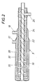
- the sampling probes Since the gas sample has to be taken from a hot reaction chamber, the sampling probes have to be protected from an inadmissible temperature load by cooling.
- the inner tube 22 is surrounded by a two-part cooling jacket 31, through the outer annular gap 32 of which the cooling liquid, in general water, is supplied in order to be drawn off in countercurrent after being deflected by an inner annular gap 33.
- Such cooling of the jacket 31 of the sampling probe 3 harbors the risk of falling below the dew point.
- the inner tube 22 is heated via an electrical resistance heater 34 to a temperature above the dew point of the gas sample, the inner tube 22 being shielded from the cooled jacket 31 by thermal insulation 35.
- This special measure means that there is no need to pay attention to a special temperature profile in the jacket cooling, because even if the dew point temperature in the area of the coolant is not reached due to the heating of the inner tube 3, there is no need to fear condensation in the inner tube 22.
Landscapes
- Health & Medical Sciences (AREA)
- Life Sciences & Earth Sciences (AREA)
- Engineering & Computer Science (AREA)
- Biomedical Technology (AREA)
- Molecular Biology (AREA)
- Physics & Mathematics (AREA)
- Chemical & Material Sciences (AREA)
- Analytical Chemistry (AREA)
- Biochemistry (AREA)
- General Health & Medical Sciences (AREA)
- General Physics & Mathematics (AREA)
- Immunology (AREA)
- Pathology (AREA)
- Sampling And Sample Adjustment (AREA)
Priority Applications (6)
| Application Number | Priority Date | Filing Date | Title |
|---|---|---|---|
| AT86890119T ATE37955T1 (de) | 1986-04-29 | 1986-04-29 | Verfahren und vorrichtung zur kontinuierlichen entnahme einer heissen gasprobe aus einem reaktionsraum fuer eine gasanalyse. |
| DE8686890119T DE3660941D1 (en) | 1986-04-29 | 1986-04-29 | Method and apparatus for continuous hot gas sampling for analysis in a reactor |
| EP86890119A EP0243569B1 (fr) | 1986-04-29 | 1986-04-29 | Procédé et dispositif de prélèvement en continu d'un échantillon de gaz chaud à analyser dans un réacteur |
| US07/030,151 US4779466A (en) | 1986-04-29 | 1987-03-25 | Method and apparatus for continuously taking a hot gas sample to be analyzed from a reaction chamber |
| CA000533984A CA1290169C (fr) | 1986-04-29 | 1987-04-07 | Sonde servant a prelever des echantillons de gaz chauds |
| DD30215587A DD256373A5 (de) | 1986-04-29 | 1987-04-27 | Verfahren und Vorrichtung zur kontinuierlichen Entnahme einer heißen Gasprobe aus einem Reaktionsraum für eine Gasanalyse |
Applications Claiming Priority (1)
| Application Number | Priority Date | Filing Date | Title |
|---|---|---|---|
| EP86890119A EP0243569B1 (fr) | 1986-04-29 | 1986-04-29 | Procédé et dispositif de prélèvement en continu d'un échantillon de gaz chaud à analyser dans un réacteur |
Publications (2)
| Publication Number | Publication Date |
|---|---|
| EP0243569A1 true EP0243569A1 (fr) | 1987-11-04 |
| EP0243569B1 EP0243569B1 (fr) | 1988-10-12 |
Family
ID=8196564
Family Applications (1)
| Application Number | Title | Priority Date | Filing Date |
|---|---|---|---|
| EP86890119A Expired EP0243569B1 (fr) | 1986-04-29 | 1986-04-29 | Procédé et dispositif de prélèvement en continu d'un échantillon de gaz chaud à analyser dans un réacteur |
Country Status (6)
| Country | Link |
|---|---|
| US (1) | US4779466A (fr) |
| EP (1) | EP0243569B1 (fr) |
| AT (1) | ATE37955T1 (fr) |
| CA (1) | CA1290169C (fr) |
| DD (1) | DD256373A5 (fr) |
| DE (1) | DE3660941D1 (fr) |
Cited By (11)
| Publication number | Priority date | Publication date | Assignee | Title |
|---|---|---|---|---|
| EP0324331A1 (fr) * | 1988-01-11 | 1989-07-19 | VOEST-ALPINE INDUSTRIEANLAGENBAU GESELLSCHAFT m.b.H. | Dispositif de prélèvement en continu d'échantillons de gaz chauds dans un réacteur |
| GB2234063A (en) * | 1989-07-04 | 1991-01-23 | British Gas Plc | Gas sampling device |
| DE9101433U1 (de) * | 1991-02-08 | 1991-04-25 | Steag Ag, 4300 Essen | Gehäuse zur Aufnahme eines Staubfilters für eine Gasentnahmesonde |
| US5039322A (en) * | 1988-01-11 | 1991-08-13 | Voest-Alpine Industrieanlangenbau Gesellschaft M.B.H. | Apparatus for extracting hot gas samples from a reaction vessel |
| FR2715732A1 (fr) * | 1994-02-02 | 1995-08-04 | Inst Francais Du Petrole | Dispositif de prélèvement fonctionnant dans des milieux à forte concentration en poussières. |
| WO1999008104A1 (fr) * | 1997-08-06 | 1999-02-18 | Axiva Gmbh | Analyse en ligne des gaz utilises lors de la preparation de cetene |
| FR2795338A1 (fr) * | 1999-06-28 | 2000-12-29 | Inst Francais Du Petrole | Dispositif de distribution pour multi-reacteurs d'evaluation automatique de catalyseurs |
| EP1467195A1 (fr) * | 2003-04-07 | 2004-10-13 | Sobotta GmbH Sondermaschinenbau | Sonde pour le prélèvement d'un échantillon de gaz |
| EP1798538A3 (fr) * | 2005-12-19 | 2007-12-19 | Horiba, Ltd. | Appareil de traitement d'échantillons et appareil de mesure |
| WO2011131866A1 (fr) * | 2010-04-22 | 2011-10-27 | Commissariat A L'energie Atomique Et Aux Energies Alternatives | Sonde de prélèvement d'échantillons, dispositif de prélèvement comportant cette sonde et procédé de prélèvement d'échantillons |
| AT12381U3 (de) * | 2011-12-06 | 2012-09-15 | Avl List Gmbh | Vorfilteranordnung für gasanalysesysteme |
Families Citing this family (20)
| Publication number | Priority date | Publication date | Assignee | Title |
|---|---|---|---|---|
| US5235190A (en) * | 1991-01-29 | 1993-08-10 | Gemini Research, Inc. | Continuous air monitoring system |
| US5507192A (en) * | 1994-09-13 | 1996-04-16 | Beaudin; Allen B. | Automated gas measurement system |
| US5777241A (en) * | 1997-02-06 | 1998-07-07 | Evenson; Euan J. | Method and apparatus for sampling and analysis of furnace off-gases |
| FR2764696B1 (fr) * | 1997-06-17 | 1999-08-13 | Inst Francais Du Petrole | Dispositif de prelevement d'echantillons de fluide comportant une vanne de controle a commande thermique |
| GB9810866D0 (en) * | 1998-05-20 | 1998-07-22 | Boc Group Plc | Furnace waste gas sampling |
| FR2780506B1 (fr) | 1998-06-25 | 2000-08-25 | Inst Francais Du Petrole | Procede et unite de prelevement d'aldehydes et cetones contenus dans des gaz d'echappement |
| JP2000081422A (ja) * | 1998-06-29 | 2000-03-21 | Nec Corp | 多点極微量物質自動分析装置及び分析方法並びに極微量物質自動分析装置及び分析方法 |
| JP2000028579A (ja) | 1998-07-08 | 2000-01-28 | Hitachi Ltd | 試料ガス採取装置及び危険物探知装置 |
| FI110033B (fi) * | 1998-07-09 | 2002-11-15 | Outokumpu Oy | Näytevirran ohjauselin |
| US6151952A (en) * | 1998-10-26 | 2000-11-28 | California Analytical Instruments, Inc. | System for mass emission sampling of combustion products |
| US6499362B1 (en) * | 2001-12-03 | 2002-12-31 | Global Fia, Inc. | In-line filter probe for process analysis |
| FI116161B (fi) * | 2002-12-23 | 2005-09-30 | Outokumpu Oy | Menetelmä ja laitteisto kaasun koostumuksen mittaamiseksi leijupedistä |
| ITMI20060523A1 (it) * | 2006-03-22 | 2007-09-23 | Tct Tecora S R L | Sistema per il campionamento continuo delle emissioni |
| DE102006019723B4 (de) * | 2006-03-31 | 2014-12-24 | Alstom Technology Ltd. | Messsondensystem, Anordnung und Verfahren zur Erfassung von Abgasparametern stromabwärts einer Gasturbine |
| CN101936820B (zh) * | 2009-06-30 | 2012-03-07 | 同方威视技术股份有限公司 | 样品收集方法以及样品收集装置 |
| US8196479B2 (en) * | 2009-10-20 | 2012-06-12 | Midwest Research Institute, Inc. | Portable multi-tube air sampler unit |
| CN110579378B (zh) * | 2018-06-07 | 2024-06-21 | 北京航天益来电子科技有限公司 | 烟气可持续采样探杆 |
| US11287406B2 (en) * | 2019-04-15 | 2022-03-29 | Mustang Sampling, Llc | Multi-input auto-switching gas sample conditioning system |
| DK180857B1 (en) * | 2020-01-13 | 2022-05-20 | Flo2R Aps | Gas sampling apparatus for extraction of gaseous samples |
| CN112362417B (zh) * | 2020-11-21 | 2025-02-14 | 西安热工研究院有限公司 | 一种双脉冲差相反吹烟气采样装置及方法 |
Citations (3)
| Publication number | Priority date | Publication date | Assignee | Title |
|---|---|---|---|---|
| US3748906A (en) * | 1970-10-15 | 1973-07-31 | Jones & Laughlin Steel Corp | Gas sampling apparatus |
| US4272481A (en) * | 1979-05-21 | 1981-06-09 | The Dow Chemical Company | System and method for providing a vapor phase sample for analysis |
| EP0095802A1 (fr) * | 1982-05-28 | 1983-12-07 | CENTRE DE RECHERCHES METALLURGIQUES CENTRUM VOOR RESEARCH IN DE METALLURGIE Association sans but lucratif | Perfectionnements aux dispositifs de prélèvement d'échantillons gazeux |
Family Cites Families (2)
| Publication number | Priority date | Publication date | Assignee | Title |
|---|---|---|---|---|
| JPS5814976B2 (ja) * | 1976-08-19 | 1983-03-23 | トヨタ自動車株式会社 | エンジンの図示平均有効圧力変動率測定方法及び装置 |
| EP0081637A1 (fr) * | 1981-11-10 | 1983-06-22 | Krupp Polysius Ag | Appareil pour prélèvement et analyse d'échantillons contenant de la poussière |
-
1986
- 1986-04-29 DE DE8686890119T patent/DE3660941D1/de not_active Expired
- 1986-04-29 EP EP86890119A patent/EP0243569B1/fr not_active Expired
- 1986-04-29 AT AT86890119T patent/ATE37955T1/de not_active IP Right Cessation
-
1987
- 1987-03-25 US US07/030,151 patent/US4779466A/en not_active Expired - Lifetime
- 1987-04-07 CA CA000533984A patent/CA1290169C/fr not_active Expired - Lifetime
- 1987-04-27 DD DD30215587A patent/DD256373A5/de unknown
Patent Citations (3)
| Publication number | Priority date | Publication date | Assignee | Title |
|---|---|---|---|---|
| US3748906A (en) * | 1970-10-15 | 1973-07-31 | Jones & Laughlin Steel Corp | Gas sampling apparatus |
| US4272481A (en) * | 1979-05-21 | 1981-06-09 | The Dow Chemical Company | System and method for providing a vapor phase sample for analysis |
| EP0095802A1 (fr) * | 1982-05-28 | 1983-12-07 | CENTRE DE RECHERCHES METALLURGIQUES CENTRUM VOOR RESEARCH IN DE METALLURGIE Association sans but lucratif | Perfectionnements aux dispositifs de prélèvement d'échantillons gazeux |
Cited By (18)
| Publication number | Priority date | Publication date | Assignee | Title |
|---|---|---|---|---|
| EP0324331A1 (fr) * | 1988-01-11 | 1989-07-19 | VOEST-ALPINE INDUSTRIEANLAGENBAU GESELLSCHAFT m.b.H. | Dispositif de prélèvement en continu d'échantillons de gaz chauds dans un réacteur |
| US5039322A (en) * | 1988-01-11 | 1991-08-13 | Voest-Alpine Industrieanlangenbau Gesellschaft M.B.H. | Apparatus for extracting hot gas samples from a reaction vessel |
| GB2234063A (en) * | 1989-07-04 | 1991-01-23 | British Gas Plc | Gas sampling device |
| GB2234063B (en) * | 1989-07-04 | 1993-01-20 | British Gas Plc | Gas sampling device |
| DE9101433U1 (de) * | 1991-02-08 | 1991-04-25 | Steag Ag, 4300 Essen | Gehäuse zur Aufnahme eines Staubfilters für eine Gasentnahmesonde |
| FR2715732A1 (fr) * | 1994-02-02 | 1995-08-04 | Inst Francais Du Petrole | Dispositif de prélèvement fonctionnant dans des milieux à forte concentration en poussières. |
| WO1999008104A1 (fr) * | 1997-08-06 | 1999-02-18 | Axiva Gmbh | Analyse en ligne des gaz utilises lors de la preparation de cetene |
| US6284547B1 (en) | 1997-08-06 | 2001-09-04 | Axiva Gmbh | On-line analysis of process gas during the production of ketene |
| EP1064992A1 (fr) * | 1999-06-28 | 2001-01-03 | Institut Francais Du Petrole | Dispositif de distribution pour multi-réacteurs |
| FR2795338A1 (fr) * | 1999-06-28 | 2000-12-29 | Inst Francais Du Petrole | Dispositif de distribution pour multi-reacteurs d'evaluation automatique de catalyseurs |
| US6558625B1 (en) | 1999-06-28 | 2003-05-06 | Institut Francais Du Petrole | Distribution device for automatic catalyst evaluation multi-reactors |
| EP1467195A1 (fr) * | 2003-04-07 | 2004-10-13 | Sobotta GmbH Sondermaschinenbau | Sonde pour le prélèvement d'un échantillon de gaz |
| DE10315996A1 (de) * | 2003-04-07 | 2004-10-28 | Sobotta Gmbh, Sondermaschinenbau | Sonde zur Entnahme einer Gasprobe |
| EP1798538A3 (fr) * | 2005-12-19 | 2007-12-19 | Horiba, Ltd. | Appareil de traitement d'échantillons et appareil de mesure |
| US7395725B2 (en) | 2005-12-19 | 2008-07-08 | Horiba, Ltd. | Sample treatment apparatus and sample measurement apparatus providing it |
| WO2011131866A1 (fr) * | 2010-04-22 | 2011-10-27 | Commissariat A L'energie Atomique Et Aux Energies Alternatives | Sonde de prélèvement d'échantillons, dispositif de prélèvement comportant cette sonde et procédé de prélèvement d'échantillons |
| FR2959311A1 (fr) * | 2010-04-22 | 2011-10-28 | Commissariat Energie Atomique | Sonde de prelevement d'echantillons, dispositif de prelevement comportant cette sonde et procede de prelevement d'echantillons |
| AT12381U3 (de) * | 2011-12-06 | 2012-09-15 | Avl List Gmbh | Vorfilteranordnung für gasanalysesysteme |
Also Published As
| Publication number | Publication date |
|---|---|
| ATE37955T1 (de) | 1988-10-15 |
| DE3660941D1 (en) | 1988-11-17 |
| US4779466A (en) | 1988-10-25 |
| EP0243569B1 (fr) | 1988-10-12 |
| DD256373A5 (de) | 1988-05-04 |
| CA1290169C (fr) | 1991-10-08 |
Similar Documents
| Publication | Publication Date | Title |
|---|---|---|
| EP0243569B1 (fr) | Procédé et dispositif de prélèvement en continu d'un échantillon de gaz chaud à analyser dans un réacteur | |
| AT398389B (de) | Verfahren und anlage zur trennung von feststoff-flüssigkeit-mischungen | |
| DE1571763B1 (de) | Vorrichtung zum abscheiden von feinstaeuben aus gasen | |
| DE1811815A1 (de) | Vorrichtung zur diskontinuierlichen Probenahme aus einem Gasgemisch | |
| EP0343471A1 (fr) | Procédé de valorisation de déchets | |
| DE69412136T2 (de) | Verfahren und vorrichtung zur schnellen kontinuierlichen analyse eines gasgemisches | |
| EP0755712A1 (fr) | Procédé et installation pour la purification de gaz chargé de poussière | |
| DD148172A3 (de) | Verfahren und anordnung zur kontinuierlichen probenahme von rohgasen | |
| WO2004053023A1 (fr) | Appareil de refroidissement pour gaz de four a coke | |
| DE3622145A1 (de) | Vorrichtung zum entfernen von kondensierbaren bestandteilen aus gasen | |
| DE3505729A1 (de) | Verfahren zur reinigung von filterelementen | |
| DE19527557B4 (de) | Verfahren und Vorrichtung zur Reinigung von Gasen | |
| DE2501873B2 (de) | Verfahren und vorrichtung zum entfernen von schlacke von geschmolzenem metall | |
| DE102021124693A1 (de) | Messgassonde, Messsystem und Verfahren zur Messung von gasförmigen Rauchgasbestandteilen | |
| EP0324331A1 (fr) | Dispositif de prélèvement en continu d'échantillons de gaz chauds dans un réacteur | |
| WO1992014130A1 (fr) | Dispositif pour installation de preparation de gaz de mesure a des fins d'analyse | |
| DE202021105125U1 (de) | Messgassonde und Messsystem zur Messung von gasförmigen Rauchgasbestandteilen | |
| EP0451345A2 (fr) | Appareil pour la préparation des échantillons de gaz pour analyse | |
| DE3344163C2 (fr) | ||
| DE2836772C2 (de) | Vorrichtung zum Entfernen von Feststoffen aus einem in einem Wirbelbett behandelten Gas | |
| DE1813518B2 (de) | Vorrichtung zur entnahme von staubhaltigen gasproben | |
| DE19939636B4 (de) | Verfahren zur kontinuierlichen Probenahme von Rohgasen | |
| DE4111377C2 (fr) | ||
| DE2848666C2 (de) | Vorrichtung zum Reinigen von Gasen | |
| DE19920332B4 (de) | Prozeßreaktor zur Behandlung von Halbleitersubstraten und Verfahren zur Durchführung eines Prozesses |
Legal Events
| Date | Code | Title | Description |
|---|---|---|---|
| PUAI | Public reference made under article 153(3) epc to a published international application that has entered the european phase |
Free format text: ORIGINAL CODE: 0009012 |
|
| AK | Designated contracting states |
Kind code of ref document: A1 Designated state(s): AT BE CH DE FR GB IT LI LU NL SE |
|
| 17P | Request for examination filed |
Effective date: 19871001 |
|
| 17Q | First examination report despatched |
Effective date: 19880201 |
|
| RAP1 | Party data changed (applicant data changed or rights of an application transferred) |
Owner name: VOEST-ALPINE INDUSTRIEANLAGENBAU GESELLSCHAFT M.B. |
|
| GRAA | (expected) grant |
Free format text: ORIGINAL CODE: 0009210 |
|
| AK | Designated contracting states |
Kind code of ref document: B1 Designated state(s): AT BE CH DE FR GB IT LI LU NL SE |
|
| REF | Corresponds to: |
Ref document number: 37955 Country of ref document: AT Date of ref document: 19881015 Kind code of ref document: T |
|
| REF | Corresponds to: |
Ref document number: 3660941 Country of ref document: DE Date of ref document: 19881117 |
|
| GBT | Gb: translation of ep patent filed (gb section 77(6)(a)/1977) | ||
| ITF | It: translation for a ep patent filed | ||
| ET | Fr: translation filed | ||
| PLBE | No opposition filed within time limit |
Free format text: ORIGINAL CODE: 0009261 |
|
| STAA | Information on the status of an ep patent application or granted ep patent |
Free format text: STATUS: NO OPPOSITION FILED WITHIN TIME LIMIT |
|
| 26N | No opposition filed | ||
| ITTA | It: last paid annual fee | ||
| EPTA | Lu: last paid annual fee | ||
| EAL | Se: european patent in force in sweden |
Ref document number: 86890119.0 |
|
| REG | Reference to a national code |
Ref country code: GB Ref legal event code: IF02 |
|
| PGFP | Annual fee paid to national office [announced via postgrant information from national office to epo] |
Ref country code: SE Payment date: 20050412 Year of fee payment: 20 Ref country code: NL Payment date: 20050412 Year of fee payment: 20 Ref country code: FR Payment date: 20050412 Year of fee payment: 20 Ref country code: CH Payment date: 20050412 Year of fee payment: 20 |
|
| PGFP | Annual fee paid to national office [announced via postgrant information from national office to epo] |
Ref country code: AT Payment date: 20050414 Year of fee payment: 20 |
|
| PGFP | Annual fee paid to national office [announced via postgrant information from national office to epo] |
Ref country code: LU Payment date: 20050415 Year of fee payment: 20 |
|
| PGFP | Annual fee paid to national office [announced via postgrant information from national office to epo] |
Ref country code: GB Payment date: 20050418 Year of fee payment: 20 Ref country code: DE Payment date: 20050418 Year of fee payment: 20 |
|
| PGFP | Annual fee paid to national office [announced via postgrant information from national office to epo] |
Ref country code: IT Payment date: 20050421 Year of fee payment: 20 |
|
| PGFP | Annual fee paid to national office [announced via postgrant information from national office to epo] |
Ref country code: BE Payment date: 20050509 Year of fee payment: 20 |
|
| PG25 | Lapsed in a contracting state [announced via postgrant information from national office to epo] |
Ref country code: GB Free format text: LAPSE BECAUSE OF EXPIRATION OF PROTECTION Effective date: 20060428 |
|
| PG25 | Lapsed in a contracting state [announced via postgrant information from national office to epo] |
Ref country code: NL Free format text: LAPSE BECAUSE OF EXPIRATION OF PROTECTION Effective date: 20060429 |
|
| REG | Reference to a national code |
Ref country code: GB Ref legal event code: PE20 |
|
| REG | Reference to a national code |
Ref country code: CH Ref legal event code: PL |
|
| EUG | Se: european patent has lapsed | ||
| NLV7 | Nl: ceased due to reaching the maximum lifetime of a patent |
Effective date: 20060429 |
|
| BE20 | Be: patent expired |
Owner name: *VOEST-ALPINE INDUSTRIEANLAGENBAU G.M.B.H. Effective date: 20060429 |