EP0243986A2 - Dispositif de chauffage électrique - Google Patents
Dispositif de chauffage électrique Download PDFInfo
- Publication number
- EP0243986A2 EP0243986A2 EP87108472A EP87108472A EP0243986A2 EP 0243986 A2 EP0243986 A2 EP 0243986A2 EP 87108472 A EP87108472 A EP 87108472A EP 87108472 A EP87108472 A EP 87108472A EP 0243986 A2 EP0243986 A2 EP 0243986A2
- Authority
- EP
- European Patent Office
- Prior art keywords
- wall
- temperature sensor
- tubular
- heat
- electrical heating
- Prior art date
- Legal status (The legal status is an assumption and is not a legal conclusion. Google has not performed a legal analysis and makes no representation as to the accuracy of the status listed.)
- Granted
Links
- 238000005485 electric heating Methods 0.000 title claims description 3
- 239000002184 metal Substances 0.000 claims abstract description 9
- 238000010438 heat treatment Methods 0.000 claims description 40
- 239000012530 fluid Substances 0.000 claims description 2
- 239000011324 bead Substances 0.000 description 6
- 239000007788 liquid Substances 0.000 description 3
- 239000000463 material Substances 0.000 description 3
- 238000000034 method Methods 0.000 description 3
- 229910000679 solder Inorganic materials 0.000 description 3
- 230000001154 acute effect Effects 0.000 description 2
- 238000005275 alloying Methods 0.000 description 2
- 230000001174 ascending effect Effects 0.000 description 2
- 238000013461 design Methods 0.000 description 2
- 238000001514 detection method Methods 0.000 description 2
- 239000004519 grease Substances 0.000 description 2
- 238000007654 immersion Methods 0.000 description 2
- 238000013021 overheating Methods 0.000 description 2
- OFNHPGDEEMZPFG-UHFFFAOYSA-N phosphanylidynenickel Chemical compound [P].[Ni] OFNHPGDEEMZPFG-UHFFFAOYSA-N 0.000 description 2
- 238000005476 soldering Methods 0.000 description 2
- 229910001220 stainless steel Inorganic materials 0.000 description 2
- 239000010935 stainless steel Substances 0.000 description 2
- OAICVXFJPJFONN-UHFFFAOYSA-N Phosphorus Chemical compound [P] OAICVXFJPJFONN-UHFFFAOYSA-N 0.000 description 1
- 244000089486 Phragmites australis subsp australis Species 0.000 description 1
- 229910000746 Structural steel Inorganic materials 0.000 description 1
- 230000001133 acceleration Effects 0.000 description 1
- 238000009529 body temperature measurement Methods 0.000 description 1
- 238000005219 brazing Methods 0.000 description 1
- 238000005253 cladding Methods 0.000 description 1
- 238000001816 cooling Methods 0.000 description 1
- 230000008878 coupling Effects 0.000 description 1
- 238000010168 coupling process Methods 0.000 description 1
- 238000005859 coupling reaction Methods 0.000 description 1
- 238000011161 development Methods 0.000 description 1
- 230000018109 developmental process Effects 0.000 description 1
- 238000001035 drying Methods 0.000 description 1
- 230000000694 effects Effects 0.000 description 1
- 230000037406 food intake Effects 0.000 description 1
- 235000012631 food intake Nutrition 0.000 description 1
- 238000009413 insulation Methods 0.000 description 1
- 238000005259 measurement Methods 0.000 description 1
- 238000002844 melting Methods 0.000 description 1
- 230000008018 melting Effects 0.000 description 1
- 239000002245 particle Substances 0.000 description 1
- 229910052698 phosphorus Inorganic materials 0.000 description 1
- 239000011574 phosphorus Substances 0.000 description 1
- 238000012546 transfer Methods 0.000 description 1
- 238000003466 welding Methods 0.000 description 1
Images


Classifications
-
- A—HUMAN NECESSITIES
- A47—FURNITURE; DOMESTIC ARTICLES OR APPLIANCES; COFFEE MILLS; SPICE MILLS; SUCTION CLEANERS IN GENERAL
- A47J—KITCHEN EQUIPMENT; COFFEE MILLS; SPICE MILLS; APPARATUS FOR MAKING BEVERAGES
- A47J37/00—Baking; Roasting; Grilling; Frying
- A47J37/12—Deep fat fryers, e.g. for frying fish or chips
- A47J37/1257—Deep fat fryers, e.g. for frying fish or chips electrically heated
- A47J37/1261—Details of the heating elements; Fixation of the heating elements to the frying vessel
Definitions
- the invention relates to an electrical heating of a wall for deep fryers or other devices with at least one electric heating element and a temperature sensor, which are arranged on the outside of the wall facing away from the medium to be heated.
- Such electrical heating has become known from US-A-2 360 727.
- an open electric heater is arranged in the bottom area of a deep fryer on the outside of a corrugated bottom wall forming a flow channel.
- At the bottom of a bottom shaft of this base there is an angled thermostatic part in the manner of a bimetal, which acts on the actuation button of a switch. The temperature of the medium flowing above this wall can thus be detected will.
- the thermostatic part is shielded from the heating by strong insulation and thus does not detect any heating effects.
- a deep fryer which works in the usual way with immersion heaters.
- a rod-shaped thermostat on the heating pipes, these thermostats or cladding tubes containing the thermostats touching the radiators in places.
- this also allows a partial detection of the temperature of the radiator itself, but the thermostat is arranged in the interior of the fryer in the manner of an immersion heater and is therefore disruptive and exposed to all disadvantageous influences.
- the object of the invention is to provide an electrical heating of a wall in which the medium to be heated is heated extremely gently and without the risk of overheating both during operation and in the event of any missing heated medium and is brought very quickly to the desired and set temperature and can be held on it.
- the temperature of the tubular heater which heats the medium via the wall and is therefore not in contact with the medium itself, reaches the temperature sensor on the one hand via the wall and on the other hand via the medium, so that there is a double coupling that responds extremely quickly Regulation via limitation enables without fear of switching off too early must become.
- This design is also particularly advantageous and expedient in devices other than the deep fryer described below.
- the temperature sensor is particularly advantageous for dry-running protection. If, for example, in a deep fryer, the level of the deep-frying fat lowers in a wall area above the fat level, the deep fryer is protected against overheating by switching off, because then the temperature sensor is heated by the neighboring tubular heating element directly over the wall, without the fat cooling down .
- the fryer 1 shown in Fig. 1 has a substantially elongated rectangular main container 2 made of stainless steel sheet in plan view, which with its upper, outwardly angled edge 5 hanging in a recessed section of the horizontal cover plate 4 of a cabinet made of the same or other material 3 is used.
- the cabinet 3 has on the front narrow side a door 6 and above this a dash panel 7 for indicator lights, switches or the like.
- On the bottom of the cabinet there is a drip pan 8 above which a vertical discharge nozzle 9 is inserted into the bottom of the main container 2 and is provided with a manually operated closing valve.
- the main container 2 is essentially composed of two superimposed parts, of which the upper forms the upper upright, extending to the edge 5 walls of the further part of the main container 2 in plan view, while the lower, cup-shaped part with its underside to a lower inside projecting shoulder edge of the upper part is attached and carries the drain neck 9 in its bottom.
- the surface level of the deep-frying fat which it occupies when the deep-fryer is not filled with fry is indicated by dash-dotted lines at about half the height of the upper further section of the main container 2.
- the frying fat level can extend close to the edge 5, that is to say that the frying fat space 10 extends from this maximum height of the frying fat level to the bottom of the main container 2.
- the frying chamber 11 extends from the same height down to only slightly above an inwardly projecting step floor 13 which runs around the outer walls and which separates the frying chamber 11 from an immediately downstream flow circulation shaft 14, which is formed by the lower part of the container and subsequently to the step floor 13 by its total width in its horizontal cross sections smaller than the frying room is 11.
- the two opposite longitudinal walls 15 of the shaft 14, which are at right angles to the front of the fryer, are inclined outward at the same acute angles, while the two walls 16, which are at right angles thereto, are vertical.
- the walls 15 are provided over their entire length and a height of more than half the wall height with bead-like, wavy profiles that merge directly into one another;
- the beads 17 form continuous, cross-sectionally prismatic grooves on the outside of the respective wall 15 for receiving a straight tubular heating element 18 which is continuous over the entire length of the wall.
- the tubular heating elements 18 are applied in metallic connection to the outer surface of the respective wall 15 , for example soldered or welded, but preferably by a special soldering process, for example with a nickel-phosphor solder, which creates a thermally no longer releasable connection and is also called "alloying".
- a removable insert 19 formed by a sheet metal which has an upper, at a short distance above the associated section of the step base 13 and an approximately parallel angled edge strip 20, which is at a distance from the opposing upright wall 21 of the frying chamber 11.
- the middle space between the two ascending flow channels 22 forms a descending flow channel 25 for the frying fat, which thus flows down between the inserts 19 from the frying chamber 11 and reaches the flow channels 22 above the base of the main container 2 with division on both sides, in this flows upward again under heating and acceleration and is thus effectively circulated continuously in at least two closed circuits which extend from the grease surface level to the bottom of the main container 2.
- the space below the lower ends 23 of the flow channels 22 forms a so-called "cold sump", ie a sump space 12 delimited by the bottom 26 of the main container 2, in which the temperature of the fat is substantially below the remaining container temperature and in which residues can accumulate which fall through the sieve of a frying basket 27 intended for food intake and to be placed in the frying chamber 11; the frying basket 27 stands on the edge strips 20 so that the heated frying fat emerging in their area flows directly into the frying basket 27.
- a fat temperature sensor 29 is arranged on the wall 28 of the frying chamber 11 adjacent to the front, which is inserted into a flat circular depression stamped into the wall on the outside of this wall 28 and lies at a distance of approx. 2 is up to 3 mm from its base plate so that grease can flow past the entire circumference.
- the temperature sensor 29 is used for the manually adjustable regulation of the electrical power supply to the tubular heating element 18.
- a straight-line temperature sensor 30 is provided, which in this case responds mainly to the temperature of the tubular heating element 18 as protection against drying out, so that fire hazards are avoided even when the fat level is below the temperature sensor 29.
- the temperature measurement described enables an excellent, quickly accessible regulation of the temperature limitation which includes both the influence of the liquid temperature and the heating influence.
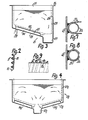
- the temperature sensor 30 can be arranged in accordance with FIGS. 7 and 8. 2 to 16, the same reference numerals as in FIG. 1 are used for corresponding parts, but with small letters as indices.
- Fig. 2 shows the preferably triangular cross sections of the tubular heaters 18 and the beads 17 to increase the contact area with the wall 15a.
- the tubular heaters 18 are approximately equilateral triangular in cross section with rounded corner areas, such that they are essentially full-area on two triangular sides rest on the bead legs of the associated bead 17.
- the beads 17 are designed in cross-section in the manner of a uniform wave profile.
- compensating strips 36 made of a material that is more thermally conductive than the wall, for example structural steel, can be provided between the outer surface of the wall and the outer surface of the tubular heating element.
- the compensating strips the thickness of which is of the order of magnitude of that in the wall, but can also be larger, have a contact surface of the tubular heating element 18 that is adjacent to them Greater width, with adjacent compensating strips 36 with their longitudinal edges directly abutting one another or integrally merging into one another in the exemplary embodiment shown.
- the temperature sensor can be attached in a heat-conducting metallic connection to the wall or the associated compensating strips 36, so that a measurement that is very quickly accessible is ensured.
- the main container 2f of a deep fryer has a bottom wall 13f which is continuous over most of its length and inclined downwards at an acute angle to the horizontal, at the lowest point of which a sump chamber 12f adjoins the associated upright wall 28f, which forms a channel which extends across the width (at right angles to the plane of the drawing) and is recessed with respect to the bottom wall 13f.
- Sheet metal parts 17f, 19f are fastened to the bottom wall 13f in such a way that flow shafts 14f are formed over the width of the frying chamber next to one another and parallel to the direction of inclination of the bottom wall 13f, their entry above and at the edge of the sump chamber 12f and their exit adjacent to the highest point the bottom wall 13f adjoining upright wall.
- the flow shafts 14f run obliquely upward from the sump chamber 12f at a relatively flat angle, preferably between 20 ° and 30 °, like the bottom wall 13f. While FIG. 3 shows an asymmetrical design with a sump chamber 12f arranged on one side and a bottom wall 13f that runs obliquely towards one side, FIG. 4 shows a symmetrical version of the main container 2g, in which the sump chamber 12g is in the middle and the bottom wall 13g is from there runs diagonally upwards on both sides.
- the bottom wall 13f is formed over almost its entire surface by an insert carrier 40, which consists of a shell-shaped recessed sheet metal part, the circumferential flange edge of which is sealingly attached to the wall of the container 2f with stud bolts 41 and an interposed seal 42. It can also be welded in.
- insert carrier 40 which consists of a shell-shaped recessed sheet metal part, the circumferential flange edge of which is sealingly attached to the wall of the container 2f with stud bolts 41 and an interposed seal 42. It can also be welded in.
- the pockets 17f are composed of half-shells 45 made of stainless steel sheet which are reversed to one another and are connected to one another by a middle longitudinal seam, and a tubular heating element 18f is applied to each half-shell, which is shaped in the form of a loop which is folded over and therefore fourfold and whose connecting ends 33f are formed protrude from the U-shaped pocket 17f which is open at the bottom and thus towards the outside of the container.
- the tubular heater 18f is attached by a process similar to brazing, which is referred to as "alloying".
- a nickel-phosphorus solder is used there, in which the metal lische jacket of the tubular heater and the material of the pocket enter into such a metallic connection that they are practically thermally inseparable, the escaping phosphorus in the soldering process ensures that the solder initially give a lower melting point.
- This connection is extremely temperature-resistant and ensures the best heat transfer.
- these ribs or pockets 17f which are parallel to one another and extend almost over the entire length of the insert, in that one of the half-shells of one pocket together with the corresponding section of the bottom 43 and one half-shell of the adjacent pocket form a U- Shaped component with a rounded edge directed outwards and tubular heating elements applied to the outside of the legs, the insert carrier 40 then being formed by welding together such parallel components along the seam 29. It is also possible to provide ribs or pockets in a different shape and, if necessary, also to provide the bottom 43 with tubular heating elements attached on the outside in a heat-conducting connection. In any case, it is important that essential wall sections of the flow chutes 14f are heated as evenly as possible.
- the mutually parallel flow shafts 14f are closed on their upper side by a cover 19f in the form of a flat sheet, essentially over their entire length.
- a cover 19f in the form of a flat sheet, essentially over their entire length.
- areas free of the cover are provided, which have an inlet opening 23f and an outlet opening Form 24f.
- the cover 19f is placed loosely and fixed in the position shown by guides or brackets, not shown, for example pins engaging in a hole in the cover on the pockets or on the container.
- the heating of the liquid in the flow chutes 14f creates a buoyancy which ensures a very rapid flow in the direction of the arrows 46 and in the entire container, as can be seen from the flow arrows in FIGS. 11 and 12. It is advantageous that in the area above the sump chamber 12f the flow is directed downwards and is then deflected to the side because this may cause entrained particles to sink into the sump chamber 14, which is excluded from the oil circulation and because of the poor heat conduction of the liquids and the fact that there is no convection, namely approximately 100 ° C, is colder than the rest of the container.
- the recessed shape of the insert carrier 40 shown in FIG. 5 saves space in the container since the pockets 17f protrude only slightly beyond the height of the container flange; however, a straight insert carrier can also be used, which enables an even better flow to the inlet and outlet openings 23f, 24f.
- the regulation and temperature limitation takes place via so-called hydraulic regulators, ie temperature regulators with a system filled with expansion fluid, which contains a tubular temperature sensor 30f which is connected via a capillary tube 47 to an expansion socket, not shown, which acts on a snap switch.
- the temperature sensor 30f is arranged in parallel at a relatively close distance next to one of the tubular heater turns, likewise in a thermally conductive connection with the associated one Wall of the half-shell 45. This can be done by means of the heat-conducting element 37i shown in FIGS.
- a temperature sensor for control and as dry-running protection can be attached in a similar manner, only at a different distance from the tubular heaters.
- a temperature sensor provided primarily as dry-running protection could be inserted into the space between two tubular heaters.
- Fig. 9 heating of a pipe is shown.
- the tubular heater 18c is arranged here helically on the outer circumference of a tube wall 15c.
- the temperature sensor 30c which is arranged helically on the outer circumference of the wall 15c between two coils of the tubular heating element 18c, is only directly thermally conductive to the wall 15c.
- a heat-conducting element 37 made of sheet metal is applied to the outer surface of the wall 15c in a metallic connection, the cross-section of which is adapted to that of the temperature sensor 30c and, after the temperature sensor has been inserted, is tightly closed by appropriate folding around the circumference of the temperature sensor 30c.
Landscapes
- Food Science & Technology (AREA)
- Engineering & Computer Science (AREA)
- Frying-Pans Or Fryers (AREA)
- Resistance Heating (AREA)
- Yarns And Mechanical Finishing Of Yarns Or Ropes (AREA)
- Beans For Foods Or Fodder (AREA)
- Conductive Materials (AREA)
- Amplifiers (AREA)
- Surgical Instruments (AREA)
- Heating, Cooling, Or Curing Plastics Or The Like In General (AREA)
- Cookers (AREA)
- Devices That Are Associated With Refrigeration Equipment (AREA)
- Discharge Heating (AREA)
- Commercial Cooking Devices (AREA)
Priority Applications (1)
| Application Number | Priority Date | Filing Date | Title |
|---|---|---|---|
| AT87108472T ATE58051T1 (de) | 1983-08-18 | 1984-07-26 | Elektrische beheizung. |
Applications Claiming Priority (2)
| Application Number | Priority Date | Filing Date | Title |
|---|---|---|---|
| DE3329793 | 1983-08-18 | ||
| DE19833329793 DE3329793A1 (de) | 1983-08-18 | 1983-08-18 | Elektrische beheizung fuer fluessigkeitsbehaelter |
Related Parent Applications (1)
| Application Number | Title | Priority Date | Filing Date |
|---|---|---|---|
| EP84108833.9 Division | 1984-07-26 |
Publications (3)
| Publication Number | Publication Date |
|---|---|
| EP0243986A2 true EP0243986A2 (fr) | 1987-11-04 |
| EP0243986A3 EP0243986A3 (en) | 1988-07-06 |
| EP0243986B1 EP0243986B1 (fr) | 1990-11-07 |
Family
ID=6206827
Family Applications (2)
| Application Number | Title | Priority Date | Filing Date |
|---|---|---|---|
| EP87108472A Expired - Lifetime EP0243986B1 (fr) | 1983-08-18 | 1984-07-26 | Dispositif de chauffage électrique |
| EP84108833A Expired EP0135707B1 (fr) | 1983-08-18 | 1984-07-26 | Friteuse électrique |
Family Applications After (1)
| Application Number | Title | Priority Date | Filing Date |
|---|---|---|---|
| EP84108833A Expired EP0135707B1 (fr) | 1983-08-18 | 1984-07-26 | Friteuse électrique |
Country Status (7)
| Country | Link |
|---|---|
| US (2) | US4574183A (fr) |
| EP (2) | EP0243986B1 (fr) |
| JP (1) | JPS6062087A (fr) |
| AT (2) | ATE33094T1 (fr) |
| DE (3) | DE3329793A1 (fr) |
| ES (1) | ES535260A0 (fr) |
| YU (1) | YU142684A (fr) |
Cited By (4)
| Publication number | Priority date | Publication date | Assignee | Title |
|---|---|---|---|---|
| FR2637781A1 (en) * | 1988-10-14 | 1990-04-20 | Inoxyform Inox Equipement Sa | Element for preparing and dispensing food products and articles of furniture incorporating such an element |
| EP1795097A1 (fr) * | 2005-12-12 | 2007-06-13 | ANGELO PO GRANDI CUCINE S.p.A. | Friteuse |
| FR2909655A1 (fr) * | 2006-12-08 | 2008-06-13 | Denis Megemont | Borne de depotage |
| ITVR20090213A1 (it) * | 2009-12-04 | 2011-06-05 | Hicook S R L | Resistenza per riscaldamento ad irraggiamento |
Families Citing this family (36)
| Publication number | Priority date | Publication date | Assignee | Title |
|---|---|---|---|---|
| JPS62500430A (ja) * | 1984-09-24 | 1987-02-26 | ニロ プラン アクチエンゲゼルシヤフト | 電気的な面状の加熱体及び、鍋本体と槽部分と槽底部とを有するフライ鍋 |
| DE3526186A1 (de) * | 1985-07-23 | 1987-02-05 | Ego Elektro Blanc & Fischer | Elektrische beheizung fuer fluessigkeits-behaelter |
| DE3610235A1 (de) * | 1986-03-26 | 1987-10-01 | Ego Elektro Blanc & Fischer | Friteuse |
| US4798939A (en) * | 1986-04-02 | 1989-01-17 | Gallina Corporation | Pressurized liquid cooker with integrated radiant heating apparatus |
| US4817512A (en) * | 1986-11-17 | 1989-04-04 | Vangen Sandra K | Cooking utensil |
| US4852471A (en) * | 1987-11-10 | 1989-08-01 | Jvj Enterprises, Inc. | Semiautomatic frying machine and air filter apparatus therefor |
| US4787301A (en) * | 1987-11-10 | 1988-11-29 | Little Chipper, Inc. | Deep fat cooking apparatus and method |
| DE3804327A1 (de) * | 1988-02-12 | 1989-08-24 | Ego Elektro Blanc & Fischer | Medien-heizeinheit |
| US5253567A (en) * | 1993-03-05 | 1993-10-19 | Stein, Inc. | Thermal fluid heat exchanger for deep fat fryer |
| US5445062A (en) * | 1993-05-21 | 1995-08-29 | Polster; Louis S. | Cooker/rethermalizer |
| DE4342727C1 (de) * | 1993-12-15 | 1995-04-13 | Frifri Aro Gmbh | Friteuse |
| FR2723690B1 (fr) * | 1994-08-17 | 1996-09-27 | Seb Sa | Appareil de chauffe pour aliments, en particulier pour la realisation de fritures, comportant une contre-cuve |
| DE19500896C2 (de) * | 1995-01-13 | 1996-11-21 | Neubauer Kurt Maschf | Gerät zum Backen oder Fritieren, insbesondere Friteuse mit Induktionsheizung |
| US5961866A (en) * | 1996-03-27 | 1999-10-05 | Alto-Shaam, Inc. | Food heating unit |
| US5973297A (en) * | 1996-03-28 | 1999-10-26 | Henny Penny Corporation | Apparatus and method for heat regulation of deep fat fryer |
| FR2750590B1 (fr) * | 1996-07-03 | 1998-10-09 | Seb Sa | Friteuse a cuve amovible |
| US5832810A (en) * | 1997-01-10 | 1998-11-10 | Marine Kleen, Inc. | Cooking fluid container and storage system and method |
| WO1999008582A1 (fr) * | 1997-08-18 | 1999-02-25 | Henny Penny Corporation | Appareil et procede visant a reguler la chaleur d'une friteuse |
| IT245334Y1 (it) * | 1998-12-10 | 2002-03-20 | Electrolux Zanussi Grandi Impi | Friggitrice a gas con vasca di riscaldamento perfezionata |
| FR2789872B1 (fr) * | 1999-02-19 | 2001-05-18 | Seb Sa | Dispositif de securite pour appareil electrique de cuisson a cuve amovible |
| KR100372570B1 (ko) * | 1999-11-02 | 2003-02-17 | 주식회사 성창베네피나 | 전자유도용 조리용기 |
| US6573483B1 (en) * | 2000-03-15 | 2003-06-03 | The Holmes Group, Inc. | Programmable slow-cooker appliance |
| US6428627B1 (en) * | 2000-03-15 | 2002-08-06 | Hatco Corporation | Flow heater |
| JP2003180533A (ja) * | 2001-12-17 | 2003-07-02 | Paloma Ind Ltd | 液体加熱調理器 |
| US20090087534A1 (en) * | 2002-08-14 | 2009-04-02 | Mclemore John D | Cooking apparatus |
| US6677556B1 (en) * | 2002-10-28 | 2004-01-13 | Ya Horng Electronic Co., Ltd. | Inner pot of an electric fryer |
| US7141764B1 (en) | 2004-08-31 | 2006-11-28 | Shumate Eldridge J | Externally heated deep fat fryer |
| US8186265B2 (en) | 2005-08-08 | 2012-05-29 | Ron's Enterprises, Inc. | Device to efficiently cook food |
| US8707857B2 (en) * | 2005-08-08 | 2014-04-29 | Ronald M. Popeil | Cooking device to deep fat fry foods |
| US8850965B2 (en) | 2005-08-08 | 2014-10-07 | Ronald M. Popeil | Device to efficiently cook food |
| US20080022994A1 (en) * | 2006-07-28 | 2008-01-31 | Frymaster L.L.C. | Open pot gas fryer with corrugated bottom |
| USD694058S1 (en) * | 2013-02-21 | 2013-11-26 | Agostino Difante | Rectangular stock pot multi-cooker |
| USD695057S1 (en) * | 2013-02-21 | 2013-12-10 | Agostino Difante | Rectangular multi-cooker |
| US20150027319A1 (en) * | 2013-03-15 | 2015-01-29 | Jeff Wu | Sous-vide cooking chamber |
| US10736463B2 (en) * | 2016-03-17 | 2020-08-11 | Henny Penny Corporation | Multiport/rotary valve sensor using hall effect control |
| US10412981B2 (en) | 2017-02-27 | 2019-09-17 | Ronald M. Popeil | System and method for deep frying poultry while avoiding skin damage |
Family Cites Families (35)
| Publication number | Priority date | Publication date | Assignee | Title |
|---|---|---|---|---|
| US3217633A (en) * | 1965-11-16 | Semi-tube fryers | ||
| DE594078C (de) * | 1931-01-21 | 1934-03-10 | Elek Sche Heizung A G Vorm S B | Elektrisch beheizter Kochkessel mit indirekter Beheizung durch ein Fluessigkeitsbad |
| US1907265A (en) * | 1932-02-13 | 1933-05-02 | George H Schwedersky | Cooking utensil |
| GB489921A (en) * | 1938-03-18 | 1938-08-05 | W T French & Son Ltd | Improvements connected with electric kettles |
| US2360727A (en) * | 1943-12-29 | 1944-10-17 | Harold N Shaw | Fry kettle |
| FR935297A (fr) * | 1946-10-23 | 1948-06-15 | Electro App | Perfectionnements aux bouilloires électriques |
| US2528776A (en) * | 1947-01-13 | 1950-11-07 | Phillip M Pappas | Deep fat frying apparatus |
| GB668613A (en) * | 1949-08-16 | 1952-03-19 | Hermann Oberlaender | Improvements relating to frying apparatus |
| US2694769A (en) * | 1950-04-22 | 1954-11-16 | Knapp Monarch Co | Heating element for vacuum type coffee makers and the like |
| US2703358A (en) * | 1952-01-25 | 1955-03-01 | Stevens Mfg Co Inc | Hot cup |
| US3384195A (en) * | 1955-04-15 | 1968-05-21 | Sunbeam Corp | Electric frying pan |
| GB807354A (en) * | 1956-08-10 | 1959-01-14 | Benham & Sons Ltd | Improvements in fat frying vessels |
| GB863118A (en) * | 1957-03-13 | 1961-03-15 | Owen Evans | Electrically heated cooking utensils |
| DE1746637U (de) * | 1957-03-23 | 1957-06-13 | Caspar Cloer Fa | Befestigung von mit isolierstoff in rohre eingepressten heizwendeln in topfboeden. |
| US3007029A (en) * | 1958-02-17 | 1961-10-31 | Gen Electric | Temperature responsive control for electrically heated devices |
| DE1154604B (de) * | 1960-01-14 | 1963-09-19 | Willi Brandl | Backeinrichtung |
| US3194662A (en) * | 1963-06-04 | 1965-07-13 | Ballantyne Instr And Electroni | Method of deep fat frying and cooking |
| US3317709A (en) * | 1964-05-11 | 1967-05-02 | Mc Graw Edison Co | Electric griddle |
| US3511971A (en) * | 1967-08-24 | 1970-05-12 | Richard T Keating | Temperature control |
| DE1978694U (de) * | 1967-11-25 | 1968-02-15 | Thomas K G H | Elektrisch beheizte friteuse. |
| US3528776A (en) * | 1968-04-30 | 1970-09-15 | Monie S Hudson | Method for determination of copper-chrome-arsenic preservatives in treated wood |
| US3622754A (en) * | 1970-07-24 | 1971-11-23 | Gen Electric | Glass plate surface heating unit with even temperature distribution |
| US3690246A (en) * | 1970-10-14 | 1972-09-12 | Golden Skillet Corp | Apparatus for frying chicken |
| GB1282252A (en) * | 1971-01-07 | 1972-07-19 | Grandeur Aluminium Ware Mfg Co | Immersion heaters |
| US3714889A (en) * | 1971-03-04 | 1973-02-06 | R Mazzola | Outdoor deep fryer |
| CH546566A (fr) * | 1972-01-11 | 1974-03-15 | Wenger Fredy | Friteuse. |
| BE793669A (fr) * | 1972-01-15 | 1973-05-02 | Patzner K G Fabrik Fur Maschin | Friteuse |
| US3878360A (en) * | 1973-08-31 | 1975-04-15 | Sunbeam Corp | Liquid heating and dispensing appliance |
| CH573739A5 (fr) * | 1973-09-25 | 1976-03-31 | Schmid Charles | |
| US3881090A (en) * | 1973-12-03 | 1975-04-29 | Rival Manufacturing Co | Electric cooking utensil having a removable ceramic vessel |
| US3895216A (en) * | 1974-09-30 | 1975-07-15 | Gen Electric | Low thermal mass solid plate surface heating unit |
| US3971307A (en) * | 1975-08-14 | 1976-07-27 | Wyott Corporation | Deep fat fryer |
| CH608182A5 (en) * | 1976-03-01 | 1978-12-29 | Aro Sa | Deep-fat fryer |
| US4039777A (en) * | 1976-06-23 | 1977-08-02 | General Electric Company | Heating apparatus for glass or ceramic cooking vessel |
| US4138606A (en) * | 1977-08-29 | 1979-02-06 | General Electric Company | Cooking appliance |
-
1983
- 1983-08-18 DE DE19833329793 patent/DE3329793A1/de not_active Withdrawn
-
1984
- 1984-07-26 AT AT84108833T patent/ATE33094T1/de active
- 1984-07-26 DE DE8484108833T patent/DE3469995D1/de not_active Expired
- 1984-07-26 EP EP87108472A patent/EP0243986B1/fr not_active Expired - Lifetime
- 1984-07-26 EP EP84108833A patent/EP0135707B1/fr not_active Expired
- 1984-07-26 AT AT87108472T patent/ATE58051T1/de not_active IP Right Cessation
- 1984-07-26 DE DE8787108472T patent/DE3483584D1/de not_active Expired - Lifetime
- 1984-08-14 US US06/640,564 patent/US4574183A/en not_active Expired - Fee Related
- 1984-08-16 YU YU01426/84A patent/YU142684A/xx unknown
- 1984-08-17 ES ES535260A patent/ES535260A0/es active Granted
- 1984-08-17 JP JP59170550A patent/JPS6062087A/ja active Pending
-
1985
- 1985-12-11 US US06/807,827 patent/US4691096A/en not_active Expired - Fee Related
Cited By (5)
| Publication number | Priority date | Publication date | Assignee | Title |
|---|---|---|---|---|
| FR2637781A1 (en) * | 1988-10-14 | 1990-04-20 | Inoxyform Inox Equipement Sa | Element for preparing and dispensing food products and articles of furniture incorporating such an element |
| EP1795097A1 (fr) * | 2005-12-12 | 2007-06-13 | ANGELO PO GRANDI CUCINE S.p.A. | Friteuse |
| FR2909655A1 (fr) * | 2006-12-08 | 2008-06-13 | Denis Megemont | Borne de depotage |
| WO2008084146A3 (fr) * | 2006-12-08 | 2009-01-22 | Denis Megemont | Borne de depotage |
| ITVR20090213A1 (it) * | 2009-12-04 | 2011-06-05 | Hicook S R L | Resistenza per riscaldamento ad irraggiamento |
Also Published As
| Publication number | Publication date |
|---|---|
| EP0135707B1 (fr) | 1988-03-23 |
| EP0135707A1 (fr) | 1985-04-03 |
| DE3329793A1 (de) | 1985-02-28 |
| US4574183A (en) | 1986-03-04 |
| EP0243986A3 (en) | 1988-07-06 |
| JPS6062087A (ja) | 1985-04-10 |
| US4691096A (en) | 1987-09-01 |
| YU142684A (en) | 1986-10-31 |
| DE3469995D1 (en) | 1988-04-28 |
| ES8505154A1 (es) | 1985-05-01 |
| EP0243986B1 (fr) | 1990-11-07 |
| ES535260A0 (es) | 1985-05-01 |
| DE3483584D1 (de) | 1990-12-13 |
| ATE33094T1 (de) | 1988-04-15 |
| ATE58051T1 (de) | 1990-11-15 |
Similar Documents
| Publication | Publication Date | Title |
|---|---|---|
| EP0243986B1 (fr) | Dispositif de chauffage électrique | |
| DE69812546T2 (de) | Flüssigkeitserhitzungsgerät | |
| DE19713796B4 (de) | Elektrisches Kochgerät, besonders Friteuse | |
| EP0238955B1 (fr) | Dispositif de chauffage de fluides | |
| DE3526186A1 (de) | Elektrische beheizung fuer fluessigkeits-behaelter | |
| EP0221575B1 (fr) | Appareil de chauffage et/ou à cuire avec un bloc d'accumulation de chaleur | |
| DE3407965A1 (de) | Grillplatte | |
| DE2850639A1 (de) | Heizungsbaugruppe fuer die unterteilungsplatte eines perkolators oder eines durchseihfilters | |
| DE10131995A1 (de) | Heizeinsatz für ein elektrisch beheizbares Kochgefäß | |
| EP0230496B1 (fr) | Dispositif de réglage de température, en particulier pour liquides ou gaz | |
| DE69419484T2 (de) | Form und Anordnung der Bauelemente eines Fleischgrillgerätes mit Kunststoffgehäuse | |
| DE3718836A1 (de) | Heizvorrichtung mit einem elektrischen heizkoerper | |
| DE4337394A1 (de) | Steueranordnung für Geräte zum Erhitzen von Flüssigkeit | |
| DE69716178T2 (de) | Elektrisches Kochgerät | |
| DE19907072B4 (de) | Friteuse | |
| EP0327889B1 (fr) | Unité pour chauffer des fluides | |
| DE19716972A1 (de) | Vorrichtung zum Zubereiten von Lebensmitteln, insbesondere Grillvorrichtung | |
| DE69600241T2 (de) | Elektrisches Fritiergerät | |
| DE10033294A1 (de) | Rost für einen Grill, insbesondere einen Gartengrill | |
| DE2903250C2 (de) | Kessel zum Erhitzen und Speichern von Wasser | |
| EP4193894B1 (fr) | Gril à gaz extérieur | |
| DE60000291T2 (de) | Kochvorrichtung | |
| DE19747484C1 (de) | Gasbrenner mit einem Brennkörper | |
| AT406008B (de) | Vorrichtung zur zubereitung von speisen | |
| DE4029513A1 (de) | Medienerhitzer fuer fluessigkeitsbetriebene heizkoerper |
Legal Events
| Date | Code | Title | Description |
|---|---|---|---|
| PUAI | Public reference made under article 153(3) epc to a published international application that has entered the european phase |
Free format text: ORIGINAL CODE: 0009012 |
|
| AC | Divisional application: reference to earlier application |
Ref document number: 135707 Country of ref document: EP |
|
| AK | Designated contracting states |
Kind code of ref document: A2 Designated state(s): AT CH DE FR GB IT LI SE |
|
| PUAL | Search report despatched |
Free format text: ORIGINAL CODE: 0009013 |
|
| AK | Designated contracting states |
Kind code of ref document: A3 Designated state(s): AT CH DE FR GB IT LI SE |
|
| 17P | Request for examination filed |
Effective date: 19880622 |
|
| 17Q | First examination report despatched |
Effective date: 19890712 |
|
| GRAA | (expected) grant |
Free format text: ORIGINAL CODE: 0009210 |
|
| AC | Divisional application: reference to earlier application |
Ref document number: 135707 Country of ref document: EP |
|
| AK | Designated contracting states |
Kind code of ref document: B1 Designated state(s): AT CH DE FR GB IT LI SE |
|
| REF | Corresponds to: |
Ref document number: 58051 Country of ref document: AT Date of ref document: 19901115 Kind code of ref document: T |
|
| REF | Corresponds to: |
Ref document number: 3483584 Country of ref document: DE Date of ref document: 19901213 |
|
| GBT | Gb: translation of ep patent filed (gb section 77(6)(a)/1977) | ||
| ITF | It: translation for a ep patent filed | ||
| ET | Fr: translation filed | ||
| PGFP | Annual fee paid to national office [announced via postgrant information from national office to epo] |
Ref country code: GB Payment date: 19910715 Year of fee payment: 8 |
|
| PGFP | Annual fee paid to national office [announced via postgrant information from national office to epo] |
Ref country code: SE Payment date: 19910723 Year of fee payment: 8 |
|
| ITTA | It: last paid annual fee | ||
| PGFP | Annual fee paid to national office [announced via postgrant information from national office to epo] |
Ref country code: CH Payment date: 19910819 Year of fee payment: 8 |
|
| PLBE | No opposition filed within time limit |
Free format text: ORIGINAL CODE: 0009261 |
|
| STAA | Information on the status of an ep patent application or granted ep patent |
Free format text: STATUS: NO OPPOSITION FILED WITHIN TIME LIMIT |
|
| 26N | No opposition filed | ||
| PGFP | Annual fee paid to national office [announced via postgrant information from national office to epo] |
Ref country code: FR Payment date: 19920716 Year of fee payment: 9 |
|
| PG25 | Lapsed in a contracting state [announced via postgrant information from national office to epo] |
Ref country code: GB Effective date: 19920726 |
|
| PG25 | Lapsed in a contracting state [announced via postgrant information from national office to epo] |
Ref country code: SE Effective date: 19920727 |
|
| PG25 | Lapsed in a contracting state [announced via postgrant information from national office to epo] |
Ref country code: LI Effective date: 19920731 Ref country code: CH Effective date: 19920731 |
|
| GBPC | Gb: european patent ceased through non-payment of renewal fee |
Effective date: 19920726 |
|
| REG | Reference to a national code |
Ref country code: CH Ref legal event code: PL |
|
| PG25 | Lapsed in a contracting state [announced via postgrant information from national office to epo] |
Ref country code: FR Effective date: 19940331 |
|
| REG | Reference to a national code |
Ref country code: FR Ref legal event code: ST |
|
| EUG | Se: european patent has lapsed |
Ref document number: 87108472.9 Effective date: 19930204 |
|
| PGFP | Annual fee paid to national office [announced via postgrant information from national office to epo] |
Ref country code: AT Payment date: 19950721 Year of fee payment: 12 |
|
| PGFP | Annual fee paid to national office [announced via postgrant information from national office to epo] |
Ref country code: DE Payment date: 19950918 Year of fee payment: 12 |
|
| PG25 | Lapsed in a contracting state [announced via postgrant information from national office to epo] |
Ref country code: AT Effective date: 19960726 |
|
| PG25 | Lapsed in a contracting state [announced via postgrant information from national office to epo] |
Ref country code: DE Effective date: 19970402 |