EP0244656A1 - Einspannvorrichtung für Nadeln - Google Patents
Einspannvorrichtung für Nadeln Download PDFInfo
- Publication number
- EP0244656A1 EP0244656A1 EP87105158A EP87105158A EP0244656A1 EP 0244656 A1 EP0244656 A1 EP 0244656A1 EP 87105158 A EP87105158 A EP 87105158A EP 87105158 A EP87105158 A EP 87105158A EP 0244656 A1 EP0244656 A1 EP 0244656A1
- Authority
- EP
- European Patent Office
- Prior art keywords
- needle
- needles
- clamping device
- grooves
- clamping
- Prior art date
- Legal status (The legal status is an assumption and is not a legal conclusion. Google has not performed a legal analysis and makes no representation as to the accuracy of the status listed.)
- Granted
Links
Images
Classifications
-
- D—TEXTILES; PAPER
- D04—BRAIDING; LACE-MAKING; KNITTING; TRIMMINGS; NON-WOVEN FABRICS
- D04B—KNITTING
- D04B27/00—Details of, or auxiliary devices incorporated in, warp knitting machines, restricted to machines of this kind
- D04B27/06—Needle bars; Sinker bars
Definitions
- the present invention relates to a clamping device for needles, in particular crochet needles.
- Such jigs are such. B. used for crochet gallon machines, as is apparent from EP-OS 110 271 (28-71f-ep) of the same applicant.
- the jig can also be used with Raschel machines. In any case, it is attached to the needle bar of one of these machines.
- the present invention is intended to create the possibility of clamping more than ten needles per centimeter in width.
- Opposite grooves are used for securely clamping the needle shafts, one of which is provided in one main part, the other, opposite, in the other main part.
- the grooves encompass only a small part of the height of the needle shafts, in any case significantly less than half the height of a needle shaft, so that the majority of the needle shafts lie outside the grooves.
- the inertial mass of the clamping device is reduced, which is to be accelerated constantly back and forth during the movements of the needle bar. So the working speed of the machines can be increased.
- the clamping device has two main parts made of light metal, namely a lower part 2 and an upper part 4.
- Very flat grooves 40 are milled into the lower part, between which webs 42 of substantially smaller width than that of the grooves remain.
- Grooves 44 of the same dimensions are milled into the upper part 4, between which webs 46 of the same width remain as in the lower part.
- the depth of the grooves 40 and 44 is substantially less than half the height of the needle shafts 20, so that the needle shafts are exposed over most of their height.
- the grooves are milled with a set milling cutter, and all grooves for a group of needles at the same time. Given the shallow depth of the grooves, there is no risk of damaging the webs 42 and 46.
- the webs can have widths of 0.15 or 0.2 mm.
- the needles 20 have a curved end 22 and are clamped in such a way that this end abuts the back of the upper part 4. As a result, all the needles are aligned in the simplest way in their longitudinal direction. This also enables simple replacement and realignment of individual needles.
- the clamping device is very simple and can be manufactured at low cost. Parts for attachment to the needle bar of a crochet gallon or Raschel machine have not been shown here, but are known per se.
Landscapes
- Textile Engineering (AREA)
- Engineering & Computer Science (AREA)
- Knitting Machines (AREA)
- Fluid-Damping Devices (AREA)
- Clamps And Clips (AREA)
- Impact Printers (AREA)
- Gripping Jigs, Holding Jigs, And Positioning Jigs (AREA)
- Preliminary Treatment Of Fibers (AREA)
- Load-Engaging Elements For Cranes (AREA)
- Electrical Discharge Machining, Electrochemical Machining, And Combined Machining (AREA)
- Sheet Holders (AREA)
- Surgical Instruments (AREA)
- Looms (AREA)
- Processing Of Solid Wastes (AREA)
- Hooks, Suction Cups, And Attachment By Adhesive Means (AREA)
- Body Structure For Vehicles (AREA)
- Vehicle Body Suspensions (AREA)
- Massaging Devices (AREA)
- Advancing Webs (AREA)
- Jigs For Machine Tools (AREA)
- Nitrogen And Oxygen Or Sulfur-Condensed Heterocyclic Ring Systems (AREA)
- Basic Packing Technique (AREA)
- Slide Fasteners, Snap Fasteners, And Hook Fasteners (AREA)
- Greenhouses (AREA)
- Undergarments, Swaddling Clothes, Handkerchiefs Or Underwear Materials (AREA)
- Mechanical Means For Catching Fish (AREA)
- Supports Or Holders For Household Use (AREA)
- Control Of Combustion (AREA)
- Magnetically Actuated Valves (AREA)
- Adornments (AREA)
- Orthopedics, Nursing, And Contraception (AREA)
Abstract
Description
- Die vorliegende Erfindung bezieht sich auf eine Einspannvorrichrung für Nadeln, insbesondere Häkelnadeln. Derartige Einspannvorrichtungen werden z. B. für Häkelgalonmaschinen verwendet, wie es sich aus der EP-OS 110 271 (28-71f-ep) derselben Anmelder ergibt. Die Einspannvorrichtung kann aber auch bei Raschelmaschinen verwendet werden. In jedem Falle wird sie an der Nadelbarre einer dieser Maschinen angebracht.
- Es besteht ein Bedarf, Bänder mit zehn oder mehr Fäden je Zentimeter Breite auf Häkelgalon- oder Rasschelmaschinen herzustellen. Besondere Bedeutung hat dies für elastische Bänder, wie sie für Unterwäsche und Sportwäsche benötigt werden.
- Aus der US-PS 3 823 581 - RUSSO - ist es bekannt, in den einen Hauptteil der Einspannvorrichtung dicht nebeneinander Nuten einzufräsen, von denen jede den Schaft einer Nadel aufnimmt. Der andere Hauptteil ist dort ein Klemmdeckel, der keine Nuten hat, jedoch eine vorspringende Klemmrippe. Diese dient zur Längsorientierung der Nadeln. Jede Nadel muß entsprechend mit einer Ausnehmung versehen sein. Ähnliches ist aus der oben genannten EP-OS 110 271, Figur 8 und 9, bekannt. Auch dort ist der obere Hauptteil ein reiner Klemmdeckel, was es erforderlich macht, daß der untere Hauptteil Nuten erheblicher Höhe aufweist. Nach beiden Schriften müssen die Nuten annähernd die Höhe der Nadelschäfte haben, wenn sie ihre Aufgabe, die Nadeln sicher und gegen Verdrehen festzulegen, erfüllen sollen.
- Dem Einfräsen einer größeren Anzahl von Nuten je Zentimeter Breite eines der Hauptteile der Einspannvorrichtung sind Grenzen gesetzt. Wird die Anzahl der Nuten auf über zehn je Zentimeter Breite erhöht, so ergeben sich schließlich Stege zwischen den Nuten von 0,2 oder weniger mm Breite. Dies läßt sich auch nicht durch Verwendung dünnerer Nadeln vermeiden, denn die Nadeln müssen eine bestimmte Stabilität haben, so daß die Verwendung von Nadeln unterhalb von 0,4 mm Breite unzweckmäßig ist.
- Werden zum Einfräsen der Nuten Satzfräser verwendet, so kann man zwar eine Gruppe nebeneinanderliegender Nuten in einem Arbeitsgang herstellen. Selbst dann ist es aber technisch nicht möglich, Nuten mit dazwischen verbleibenden Stegen der annähernden Höhe der Nadelschäfte und von 0,2 oder weniger mm Breite herzustellen, ohne daß dabei relativ viel Ausschuß durch zerbrochene Stege entsteht.
- Durch die vorliegende Erfindung soll die Möglichkeit geschaffen werden, mehr als zehn Nadeln je Zentimeter Breite einzuspannen.
- Zum sicheren Einspannen der Nadelschäfte dienen einander gegenüberliegende Nuten, von denen die einen in dem einen Hauptteil, die anderen, gegenüberliegend, in dem anderen Hauptteil vorgesehen sind. Die Nuten umgreifen nur einen geringen Teil der Höhe der Nadelschäfte, jedenfalls wesentlich weniger als die halbe Höhe eines Nadelschafts, so daß der größte Teil der Nadelschäfte außerhalb der Nuten liegt.
- Da die Nuten im Gegensatz zu den Vorveröffentlichungen in beiden Hauptteilen vorgesehen sind, genügt es, wenn sie eine sehr geringe Tiefe haben. Dann besteht nicht mehr die Gefahr einer Beschädigung der zwischen den Nuten verbleibenden Stege.
- Werden nach Anspruch 2 die Hauptteile aus Leichtmetall gefertigt, so wird die träge Masse der Einspannvorrichtung verringert, die bei den Bewegungen der Nadelbarre ständig hin und her zu beschleunigen ist. So kann die Arbeitsgeschwindigkeit der Maschinen erhöht werden.
- Ein Ausführungsbeispiel mit weiteren Merkmalen der Erfindung wird im folgenden anhand der Zeichnungen beschrieben.
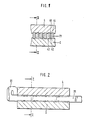
- Figur 1 ist ein Schnitt durch eine Einspannvorrichtung nach der Erfindung nach Linie I-I in Figur 2.
- Figur 2 ist ein Schnitt nach Linie II-II in Figur 1, d. h. parallel zu Längsrichtung der Nadeln.
- Die Einspannvorrichtung nach Figur 1 und 2 hat zwei aus Leichtmetall gefertigte Hauptteile, nämlich einen Unterteil 2 und einen Oberteil 4. Als Spannteile, die zum Gegeneinanderklemmen beider Hauptteile dienen, fungieren hier nicht dargestellte Schraubbolzen, die durch eine zylindrische Öffnung des Oberteils 4 in eine Gewindebohrung des Unterteils 2 greifen. In den Unterteil sind sehr flache Nuten 40 gefräst, zwischen denen Stege 42 von wesentlich geringerer Breite als die der Nuten verbleiben. In den Oberteil 4 sind Nuten 44 gleicher Abmessungen gefräst, zwischen denen Stege 46 gleicher Breite wie im Unterteil stehen bleiben. Die Tiefe der Nuten 40 und 44 ist wesentlich kleiner als die halbe Höhe der Nadelschäfte 20, so daß die Nadelschäfte über den größten Teil ihrer Höhe freiliegen.
- Die Nuten werden mit einem Satzfräser eingefräst, und zwar jeweils alle Nuten für eine Gruppe von Nadeln gleichzeitig. Bei der geringen Tiefe der Nuten ist keine Beschädigung der Stege 42 und 46 zu befürchten. Die Stege können Breiten von 0,15 oder 0,2 mm haben.
- Die Nadeln 20 haben ein gekrümmtes Ende 22 und sind so eingespannt, daß dieses Ende gegen die Rückseite des Oberteils 4 stößt. Dadurch sind alle Nadeln in ihrer Längsrichtung auf einfachste Weise ausgerichtet. Dies ermöglicht auch das einfache Auswechseln und Wiederausrichten einzelner Nadeln.
- Wie die Figuren 1 und 2 zeigen, ist die Einspannvorrichtung sehr einfach aufgebaut und kann mit geringen Kosten hergestellt werden. Teile zur Befestigung an der Nadelbarre einer Häkelgalon- oder Raschelmaschine wurden hier nicht dargestellt, sind aber an sich bekannt.
- Zum Auswechseln einzelner Nadeln werden die Schraubbolzen gelöst aber nicht entfernt. Dann werden einzelne Nadeln rückwärts herausgezogen, neue eingeschoben, die Nadelpakete gegen den Oberteil 4 ausgerichtet und die Schraubbolzen wieder festgezogen.
-
- 2 Unterteil = Hauptteil
- 4 Oberteil = Hauptteil
- 20 (Nadel-) Schaft
- 22 Ende der Nadel
- 40, 44 Nut
- 42, 46 Steg
Claims (2)
gekennzeichnet durch folgende Merkmale:
Priority Applications (1)
| Application Number | Priority Date | Filing Date | Title |
|---|---|---|---|
| AT87105158T ATE47730T1 (de) | 1984-06-02 | 1985-05-14 | Einspannvorrichtung fuer nadeln. |
Applications Claiming Priority (2)
| Application Number | Priority Date | Filing Date | Title |
|---|---|---|---|
| DE3420693A DE3420693A1 (de) | 1984-06-02 | 1984-06-02 | Einspannvorrichtung fuer haekelnadeln |
| DE3420693 | 1984-06-02 |
Related Parent Applications (1)
| Application Number | Title | Priority Date | Filing Date |
|---|---|---|---|
| EP85105904.8 Division | 1985-05-14 |
Publications (2)
| Publication Number | Publication Date |
|---|---|
| EP0244656A1 true EP0244656A1 (de) | 1987-11-11 |
| EP0244656B1 EP0244656B1 (de) | 1989-11-02 |
Family
ID=6237535
Family Applications (2)
| Application Number | Title | Priority Date | Filing Date |
|---|---|---|---|
| EP87105158A Expired EP0244656B1 (de) | 1984-06-02 | 1985-05-14 | Einspannvorrichtung für Nadeln |
| EP85105904A Expired EP0165461B1 (de) | 1984-06-02 | 1985-05-14 | Einspannvorrichtung für Häkelnadeln |
Family Applications After (1)
| Application Number | Title | Priority Date | Filing Date |
|---|---|---|---|
| EP85105904A Expired EP0165461B1 (de) | 1984-06-02 | 1985-05-14 | Einspannvorrichtung für Häkelnadeln |
Country Status (23)
| Country | Link |
|---|---|
| US (1) | US4571961A (de) |
| EP (2) | EP0244656B1 (de) |
| JP (2) | JPS60259660A (de) |
| AT (2) | ATE47730T1 (de) |
| AU (1) | AU573346B2 (de) |
| BR (1) | BR8502628A (de) |
| CA (1) | CA1253708A (de) |
| CS (1) | CS264330B2 (de) |
| DD (1) | DD239429A5 (de) |
| DE (3) | DE3420693A1 (de) |
| DK (1) | DK158840C (de) |
| ES (1) | ES287144Y (de) |
| FI (1) | FI80483C (de) |
| GR (1) | GR851329B (de) |
| HU (1) | HU207877B (de) |
| IE (1) | IE56559B1 (de) |
| IL (1) | IL75385A (de) |
| MX (1) | MX164361B (de) |
| NO (1) | NO160089C (de) |
| PL (1) | PL144327B1 (de) |
| PT (1) | PT80535B (de) |
| TR (1) | TR22415A (de) |
| ZA (2) | ZA854128B (de) |
Cited By (2)
| Publication number | Priority date | Publication date | Assignee | Title |
|---|---|---|---|---|
| WO1993006288A1 (de) * | 1991-09-24 | 1993-04-01 | Berger Gmbh | Vorrichtung zum einspannen und führen von häkelnadeln für eine häkelmaschine |
| EP3354782A1 (de) * | 2017-01-25 | 2018-08-01 | Karl Mayer Textilmaschinenfabrik GmbH | Wirkwerkzeugbarre und verfahren zum montieren von wirkwerkzeugen |
Families Citing this family (6)
| Publication number | Priority date | Publication date | Assignee | Title |
|---|---|---|---|---|
| DE4321059A1 (de) * | 1993-06-24 | 1995-01-05 | Berger Gmbh | Vorrichtung zum Einspannen und Führen von Häkelnadeln für eine Häkelmaschine |
| DE19618368B4 (de) * | 1996-05-08 | 2005-11-24 | Karl Mayer Textilmaschinenfabrik Gmbh | Anordnung aus Fadenführungselementen einer Kettenwirk- oder Strickmaschine und einem Träger |
| EP1813703B1 (de) * | 2006-01-25 | 2009-05-13 | Groz-Beckert KG | Wirknadel und Barre für diese |
| EP1988199B1 (de) * | 2007-05-03 | 2009-10-28 | Groz-Beckert KG | Wirkmaschinenwerkzeug, insbesondere für feinste Teilung |
| JP6595919B2 (ja) * | 2016-01-06 | 2019-10-23 | 大森機械工業株式会社 | 製函機 |
| CN116949659B (zh) * | 2023-03-02 | 2025-09-16 | 陕西可利雅纺织科技有限公司 | 一种经编机的导纱针调节机构 |
Citations (3)
| Publication number | Priority date | Publication date | Assignee | Title |
|---|---|---|---|---|
| US2384451A (en) * | 1941-10-07 | 1945-09-11 | Textile Machine Works | Sinker head for knitting machines |
| DE813741C (de) * | 1949-09-02 | 1951-09-17 | Arthur G Scholte | Hochleistungskettenwirkmaschine |
| US2914094A (en) * | 1958-03-18 | 1959-11-24 | Whitaker Reed Company | Loom reed having removable dents |
Family Cites Families (11)
| Publication number | Priority date | Publication date | Assignee | Title |
|---|---|---|---|---|
| GB788764A (en) * | 1955-02-23 | 1958-01-08 | Karl Mayer Erste Hessische Wir | Improvements in or relating to needle bars for warp knitting machines |
| DE1746643U (de) * | 1956-02-08 | 1957-06-13 | Arwa Feinstrumpfwirkerei G M B | Nadelbarre fuer flachwirkmaschinen. |
| US2995911A (en) * | 1959-12-10 | 1961-08-15 | Textile Machine Works | Element mounting means for straight bar knitting machines |
| US3811298A (en) * | 1972-04-10 | 1974-05-21 | K Kohl | Mounting support for the knitting needle of a warp knitting machine |
| US3823581A (en) * | 1973-02-02 | 1974-07-16 | C Russo | Knitting machine needle holder |
| FR2229255A5 (en) * | 1973-05-08 | 1974-12-06 | Inst Textile De France | Needle or platen guiding device - for hosiery looms, with stack of needle gates and sepg. walls |
| US4137730A (en) * | 1978-04-20 | 1979-02-06 | Bassist Rudolf G | Needle support assembly for a knitting machine |
| DD139140A1 (de) * | 1978-10-11 | 1979-12-12 | Dietmar Baumgaertel | Halterung fuer wirknadeln |
| FR2444740A1 (fr) * | 1978-12-18 | 1980-07-18 | Dev Meca Textile | Dispositif de barre a aiguilles pour notamment metier maille, machine a guiper, etc. |
| DE3012647A1 (de) * | 1980-04-01 | 1981-10-08 | Société de Developpement Mécanique et Textile SODEMETEX S.A., Saint Just Malmont | Nadelschiene fuer textilmaschinen, insbesondere kettenwirkmaschinen |
| DD159184A1 (de) * | 1981-05-29 | 1983-02-23 | Andreas Hering | Fassung zur halterung der wirknadeln an kettenwirkmaschinen |
-
1984
- 1984-06-02 DE DE3420693A patent/DE3420693A1/de not_active Withdrawn
-
1985
- 1985-05-14 DE DE8585105904T patent/DE3562394D1/de not_active Expired
- 1985-05-14 AT AT87105158T patent/ATE47730T1/de not_active IP Right Cessation
- 1985-05-14 EP EP87105158A patent/EP0244656B1/de not_active Expired
- 1985-05-14 DE DE8787105158T patent/DE3574033D1/de not_active Expired
- 1985-05-14 EP EP85105904A patent/EP0165461B1/de not_active Expired
- 1985-05-14 AT AT85105904T patent/ATE33859T1/de not_active IP Right Cessation
- 1985-05-23 FI FI852063A patent/FI80483C/fi not_active IP Right Cessation
- 1985-05-24 US US06/737,457 patent/US4571961A/en not_active Expired - Lifetime
- 1985-05-28 PT PT80535A patent/PT80535B/pt not_active IP Right Cessation
- 1985-05-28 TR TR26282A patent/TR22415A/xx unknown
- 1985-05-29 AU AU43120/85A patent/AU573346B2/en not_active Ceased
- 1985-05-30 ZA ZA854128A patent/ZA854128B/xx unknown
- 1985-05-30 DK DK241985A patent/DK158840C/da not_active IP Right Cessation
- 1985-05-30 MX MX205468A patent/MX164361B/es unknown
- 1985-05-30 ES ES1985287144U patent/ES287144Y/es not_active Expired
- 1985-05-30 DD DD85276811A patent/DD239429A5/de not_active IP Right Cessation
- 1985-05-30 GR GR851329A patent/GR851329B/el unknown
- 1985-05-30 ZA ZA854129A patent/ZA854129B/xx unknown
- 1985-05-31 HU HU852124A patent/HU207877B/hu not_active IP Right Cessation
- 1985-05-31 NO NO852194A patent/NO160089C/no unknown
- 1985-05-31 IE IE1356/85A patent/IE56559B1/en not_active IP Right Cessation
- 1985-05-31 CA CA000482941A patent/CA1253708A/en not_active Expired
- 1985-05-31 CS CS853926A patent/CS264330B2/cs unknown
- 1985-05-31 BR BR8502628A patent/BR8502628A/pt not_active IP Right Cessation
- 1985-05-31 PL PL1985253735A patent/PL144327B1/pl unknown
- 1985-06-02 IL IL75385A patent/IL75385A/xx not_active IP Right Cessation
- 1985-06-03 JP JP60118995A patent/JPS60259660A/ja active Granted
-
1991
- 1991-08-27 JP JP23889191A patent/JPH0726299B2/ja not_active Expired - Lifetime
Patent Citations (3)
| Publication number | Priority date | Publication date | Assignee | Title |
|---|---|---|---|---|
| US2384451A (en) * | 1941-10-07 | 1945-09-11 | Textile Machine Works | Sinker head for knitting machines |
| DE813741C (de) * | 1949-09-02 | 1951-09-17 | Arthur G Scholte | Hochleistungskettenwirkmaschine |
| US2914094A (en) * | 1958-03-18 | 1959-11-24 | Whitaker Reed Company | Loom reed having removable dents |
Cited By (3)
| Publication number | Priority date | Publication date | Assignee | Title |
|---|---|---|---|---|
| WO1993006288A1 (de) * | 1991-09-24 | 1993-04-01 | Berger Gmbh | Vorrichtung zum einspannen und führen von häkelnadeln für eine häkelmaschine |
| TR26062A (tr) * | 1991-09-24 | 1994-12-15 | Berger Gmbh | BIR ÖRGü MAKINESI ICIN,ÖRGü IGNELERININ BAGLANMA VE SEVK DüZENI. |
| EP3354782A1 (de) * | 2017-01-25 | 2018-08-01 | Karl Mayer Textilmaschinenfabrik GmbH | Wirkwerkzeugbarre und verfahren zum montieren von wirkwerkzeugen |
Also Published As
Similar Documents
| Publication | Publication Date | Title |
|---|---|---|
| DD263313A5 (de) | Garnitur fuer textilvorbereitungsmaschinen, insbesondere kaemm-maschinen, karden o. dgl. | |
| DE2622112C2 (de) | Werkzeughalter | |
| DE7504960U (de) | Drehwerkzeug mit auswechselbarem mehreckfoermigem schneideinsatz | |
| DE3001917C2 (de) | Fadenspleißvorrichtung | |
| EP0244656B1 (de) | Einspannvorrichtung für Nadeln | |
| DE10058226B4 (de) | Werkzeug zur spanabtragenden Bearbeitung von Bohrungsoberflächen | |
| EP0591470B1 (de) | Vorrichtung zum einspannen und führen von häkelnadeln für eine häkelmaschine | |
| DE2856344A1 (de) | Messeraggregat fuer eine tuftingmaschine | |
| DE1523857B2 (de) | Vorrichtung zum befestigen der spiralfeder eines uhrwerks | |
| DE2152554B2 (de) | Schneidwerkzeug | |
| EP0227018B1 (de) | Lochnadelsegment für Häkel- und Raschelmaschinen | |
| DD256533A5 (de) | Vorrichtung zur halterung von gruppen einander dicht benachbarter lochnadeln einer wirkmaschine | |
| DE102010044673B4 (de) | Wirkwerkzeugbarren-Reparaturset und Wirkwerkzeugbarre | |
| DE4320956C2 (de) | Verfahren zur Herstellung einer Sollbruchstelle an einer Maschinennadel sowie eine nach dem Verfahren hergestellte Maschinennadel | |
| DE7607041U1 (de) | Bohrstange, insbesondere fuer die metallbearbeitung | |
| DE69216919T2 (de) | Nadel für Strickmaschine | |
| DE3019139C2 (de) | Haltevorrichtung für Tuftwerkzeuge sowie Werkzeug dafür | |
| DE2925133A1 (de) | Messerblock fuer eine tuftingmaschine | |
| EP0410296A1 (de) | Deckelgarnitur für eine Karde | |
| WO1998050614A1 (de) | Greiferwebmaschine | |
| EP0748406B1 (de) | Barrenanordnung | |
| EP0670203A1 (de) | Verfahren und vorrichtung zum schneiden von in ein ries gestapeltes papier | |
| WO1995000690A1 (de) | Vorrichtung zum einspannen und führen von häkelnadeln für eine häkelmaschine | |
| DE9411291U1 (de) | Spannvorrichtung | |
| DD232938A1 (de) | Halterung fuer wirkwerkzeugfassungen an kettenwirkmaschinen |
Legal Events
| Date | Code | Title | Description |
|---|---|---|---|
| PUAI | Public reference made under article 153(3) epc to a published international application that has entered the european phase |
Free format text: ORIGINAL CODE: 0009012 |
|
| AC | Divisional application: reference to earlier application |
Ref document number: 165461 Country of ref document: EP |
|
| AK | Designated contracting states |
Kind code of ref document: A1 Designated state(s): AT BE CH DE FR GB IT LI LU NL SE |
|
| 17P | Request for examination filed |
Effective date: 19871219 |
|
| 17Q | First examination report despatched |
Effective date: 19890414 |
|
| GRAA | (expected) grant |
Free format text: ORIGINAL CODE: 0009210 |
|
| AC | Divisional application: reference to earlier application |
Ref document number: 165461 Country of ref document: EP |
|
| AK | Designated contracting states |
Kind code of ref document: B1 Designated state(s): AT BE CH DE FR GB IT LI LU NL SE |
|
| REF | Corresponds to: |
Ref document number: 47730 Country of ref document: AT Date of ref document: 19891115 Kind code of ref document: T |
|
| REF | Corresponds to: |
Ref document number: 3574033 Country of ref document: DE Date of ref document: 19891207 |
|
| GBT | Gb: translation of ep patent filed (gb section 77(6)(a)/1977) | ||
| ET | Fr: translation filed | ||
| ITF | It: translation for a ep patent filed | ||
| PLBE | No opposition filed within time limit |
Free format text: ORIGINAL CODE: 0009261 |
|
| STAA | Information on the status of an ep patent application or granted ep patent |
Free format text: STATUS: NO OPPOSITION FILED WITHIN TIME LIMIT |
|
| 26N | No opposition filed | ||
| ITTA | It: last paid annual fee | ||
| PGFP | Annual fee paid to national office [announced via postgrant information from national office to epo] |
Ref country code: GB Payment date: 19930504 Year of fee payment: 9 |
|
| PGFP | Annual fee paid to national office [announced via postgrant information from national office to epo] |
Ref country code: FR Payment date: 19930510 Year of fee payment: 9 |
|
| PGFP | Annual fee paid to national office [announced via postgrant information from national office to epo] |
Ref country code: AT Payment date: 19930512 Year of fee payment: 9 |
|
| PGFP | Annual fee paid to national office [announced via postgrant information from national office to epo] |
Ref country code: SE Payment date: 19930517 Year of fee payment: 9 Ref country code: CH Payment date: 19930517 Year of fee payment: 9 |
|
| PGFP | Annual fee paid to national office [announced via postgrant information from national office to epo] |
Ref country code: NL Payment date: 19930531 Year of fee payment: 9 |
|
| PGFP | Annual fee paid to national office [announced via postgrant information from national office to epo] |
Ref country code: BE Payment date: 19930616 Year of fee payment: 9 |
|
| PGFP | Annual fee paid to national office [announced via postgrant information from national office to epo] |
Ref country code: DE Payment date: 19930622 Year of fee payment: 9 |
|
| PGFP | Annual fee paid to national office [announced via postgrant information from national office to epo] |
Ref country code: LU Payment date: 19930702 Year of fee payment: 9 |
|
| EPTA | Lu: last paid annual fee | ||
| PG25 | Lapsed in a contracting state [announced via postgrant information from national office to epo] |
Ref country code: LU Free format text: LAPSE BECAUSE OF NON-PAYMENT OF DUE FEES Effective date: 19940514 Ref country code: GB Effective date: 19940514 Ref country code: AT Effective date: 19940514 |
|
| PG25 | Lapsed in a contracting state [announced via postgrant information from national office to epo] |
Ref country code: SE Effective date: 19940515 |
|
| PG25 | Lapsed in a contracting state [announced via postgrant information from national office to epo] |
Ref country code: LI Effective date: 19940531 Ref country code: CH Effective date: 19940531 Ref country code: BE Effective date: 19940531 |
|
| BERE | Be: lapsed |
Owner name: BERGER JOSEF Effective date: 19940531 Owner name: BERGER JOHANN Effective date: 19940531 |
|
| PG25 | Lapsed in a contracting state [announced via postgrant information from national office to epo] |
Ref country code: NL Effective date: 19941201 |
|
| GBPC | Gb: european patent ceased through non-payment of renewal fee |
Effective date: 19940514 |
|
| NLV4 | Nl: lapsed or anulled due to non-payment of the annual fee | ||
| EUG | Se: european patent has lapsed |
Ref document number: 87105158.7 Effective date: 19941210 |
|
| PG25 | Lapsed in a contracting state [announced via postgrant information from national office to epo] |
Ref country code: FR Effective date: 19950131 |
|
| REG | Reference to a national code |
Ref country code: CH Ref legal event code: PL |
|
| PG25 | Lapsed in a contracting state [announced via postgrant information from national office to epo] |
Ref country code: DE Effective date: 19950201 |
|
| EUG | Se: european patent has lapsed |
Ref document number: 87105158.7 |
|
| REG | Reference to a national code |
Ref country code: FR Ref legal event code: ST |