EP0244989A2 - Fahrzeugreibungskupplung - Google Patents
Fahrzeugreibungskupplung Download PDFInfo
- Publication number
- EP0244989A2 EP0244989A2 EP87303576A EP87303576A EP0244989A2 EP 0244989 A2 EP0244989 A2 EP 0244989A2 EP 87303576 A EP87303576 A EP 87303576A EP 87303576 A EP87303576 A EP 87303576A EP 0244989 A2 EP0244989 A2 EP 0244989A2
- Authority
- EP
- European Patent Office
- Prior art keywords
- detent
- release means
- friction clutch
- clutch according
- sleeve
- Prior art date
- Legal status (The legal status is an assumption and is not a legal conclusion. Google has not performed a legal analysis and makes no representation as to the accuracy of the status listed.)
- Withdrawn
Links
Images


Classifications
-
- F—MECHANICAL ENGINEERING; LIGHTING; HEATING; WEAPONS; BLASTING
- F16—ENGINEERING ELEMENTS AND UNITS; GENERAL MEASURES FOR PRODUCING AND MAINTAINING EFFECTIVE FUNCTIONING OF MACHINES OR INSTALLATIONS; THERMAL INSULATION IN GENERAL
- F16D—COUPLINGS FOR TRANSMITTING ROTATION; CLUTCHES; BRAKES
- F16D23/00—Details of mechanically-actuated clutches not specific for one distinct type
- F16D23/12—Mechanical clutch-actuating mechanisms arranged outside the clutch as such
- F16D23/14—Clutch-actuating sleeves or bearings; Actuating members directly connected to clutch-actuating sleeves or bearings
- F16D23/143—Arrangements or details for the connection between the release bearing and the diaphragm
- F16D23/144—With a disengaging thrust-ring distinct from the release bearing, and secured to the diaphragm
- F16D23/146—Arrangements for the connection between the thrust-ring and the release bearing
-
- Y—GENERAL TAGGING OF NEW TECHNOLOGICAL DEVELOPMENTS; GENERAL TAGGING OF CROSS-SECTIONAL TECHNOLOGIES SPANNING OVER SEVERAL SECTIONS OF THE IPC; TECHNICAL SUBJECTS COVERED BY FORMER USPC CROSS-REFERENCE ART COLLECTIONS [XRACs] AND DIGESTS
- Y10—TECHNICAL SUBJECTS COVERED BY FORMER USPC
- Y10S—TECHNICAL SUBJECTS COVERED BY FORMER USPC CROSS-REFERENCE ART COLLECTIONS [XRACs] AND DIGESTS
- Y10S192/00—Clutches and power-stop control
- Y10S192/01—Removable members
Definitions
- the invention relates to improvements in a friction clutch for a vehicle and is particularly concerned with improvements in a clutch described in our GB No. 2176262A.
- a friction clutch for a vehicle which includes a clutch release mechanism comprising a first member, a second member, a detent arranged to locate the first member in one direction relative to the second member whereby a clutch release force subsequently applied to said first member in an opposite direction will be transmitted to said second member to release the clutch and detent release means which enables the detent to be released by urging said first member further in said one direction to said second member so that the first and second members can thereafter be separated, said detent being carried by one of said members and the detent release means being carried by the other of said members whereby on separation of the members following release of the detent said detent and detent release means disengage and remain on their respective members.
- the detent is a ring held axially captive on said one member and the detent release means is a sleeve held axially captive on said other member.
- the sleeve is moved axially to engage the ring and cause the ring to expand so that it will ride on to the peripheral surface (e.g. the outer surface) of the sleeve.
- Such expansion of the ring moves it clear of a groove in said member thereby enabling the members to be separated. Separation is effected by subsequently moving said other member in the clutch release direction so that a shoulder on that member moves into abutment with the sleeve and finally disengages said other member.
- An object of the present invention is to provide a clutch in which that type of disadvantage is less likely to arise.
- a friction clutch release mechanism comprising a first member, a second member, a detent arranged to locate the first member relative to the second member on assembly by moving the first member in one direction relative to the second member whereby a clutch release force subsequently applied to said first member in an opposite direction will be transmitted to said second member to release the clutch, and detent release means having a peripheral surface for engagement with the detent, said detent release means enabling the detent to be released by urging said first member further in said one direction relative to said second member so that the detent release means engages the detent, thereby enabling said first and second members to be separated, said detent being carried by one of said members and the detent release means being carried by the other of said members whereby on separation of the members following release of the detent said detent and detent release means disengage and remain on their respective members, the detent release means having a formation on its peripheral surface which engages the detent during movement of the first member further in said one direction whereby during separation of the members following release of the detent
- the relative movement is substantially ensured by use of the formation thereby assisting in overcoming resistance to such relative movement caused by a metal chip.
- the formation may comprise a radial deformation on the detent release means.
- the formation comprises a section material which is pressed partly out of the detent release means.
- a section of the detent re lease means may extend circumferentially of the detent release means and may be inclined about an edge of the section.
- the section may have a projecting edge which forms part of an edge of the detent release means. A plurality of such sections may be provided.
- the formation comprises an aperture in the detent release means which may take the form of a circumferentially extending slot. If desired a plurality of such slots may be provided.
- the formation includes a recess, such as a circumferentially extending groove in the detent release means.
- the formation may provide a location for the detent on the detent release means during releasing movement whereby on movement of the said other member in said opposite direction, the detent resists axial movement of the detent release means with said other member.
- the formation comprises a roughened area of said peripheral surface. Substantially the whole of said peripheral surface may be roughened.
- the detent may comprise a ring and the detent release means may comprise a sleeve.
- the invention also includes a friction clutch for a vehicle which includes a clutch release mechanism comprising a first member, a second member, a detent ring arranged to locate the first member relative to the second member on assembly by moving the first member in one direction relative to the second member whereby a clutch release force subsequently applied to said first member in an opposite direction will be transmitted to said second member to release the clutch, and a detent release sleeve having a peripheral surface which includes a formation for engagement with the detent ring, said sleeve enabling the detent ring to be released by urging said first member further in said one direction relative to said second member so that the sleeve engages the detent ring and causes it to move into engagement with said formation on the sleeve, thereby enabling said first and second members to be separated, said detent ring being carried by the other of said members whereby on separation of the members following release of the detent said detent and detent release sleeve disengage and remain on their respective members.
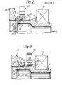
- Fig.1 there is shown a friction clutch in which a clutch pressure plate 10 is retracted by a clutch release mechanism 11 to release a clutch driven plate 12.
- Clutch release is effected by applying a force in direction A to a fulcrum plate or hub 13 of a clutch spring 14 through a short hollow shaft 15, clutch release bearing 16 and a pull member 17.
- the releasing force is applied by means of a release fork 18 which engages the pull member 17.
- the lower half of Fig.1 shows the position of shaft 15 release bearing 16, pull member 17 and fork 18 in the clutch release position.
- the spring hub 13 (constituting the aforesaid second member) has an internal peripheral groove 19 which locates a detent 20 in the form of a resilient split ring.
- the outer diameter of the split ring is less than the diameter of groove 19 to allow the ring to be expanded.
- the right hand side 22 of groove 19 as viewed in Fig.2 is of frusto conical form.
- the shaft 15 (constituting the aforesaid first member) has a frusto conical left hand leading surface 23 and is formed with a wide external groove 24.
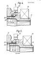
- the sleeve 25 is formed from a flat strip of steel as in Fig.6 which has a surface 60 machined to give a roughened finish, e.g. file-like. The strip is then bent into the sleeve form shown in Fig. 15 so that the roughened surface 60 forms the outer peripheral surface of the sleeve.
- the left hand end of the sleeve 25 is defined by a radial surface 21. Where the sleeve 25 abuts shoulder 27 a recess 28 is defined between shoulder 26 and the left hand end of sleeve 25.
- a force in the direction of arrow B is applied to the shaft 15 which urges the left hand end of sleeve 25 against the detent ring 20 thereby expanding the ring out of recess 28 and into the groove 19.
- the shaft 15 can then be moved in direction A to separate the spring hub 13 and shaft 15 to complete disassembly.
- the shaft 15 moves relative to the sleeve 25 until the shoulder 26 abuts the left-hand end 21 of the sleeve as in Fig.5.
- Further movement of the shaft in direction A causes the sleeve to slide from within the ring 20 until the latter disengages the sleeve 25 and finally rides down the frusto conical end surface 23 to resume the Fig.2 condition.
- the roughened surface 60 provides increased resistance to relative axial movement between the ring 20 and the sleeve 25. If some foreign matter such as a metal chip becomes jammed between the inner periphery of the sleeve 25 and the bottom groove 24 then, without the roughening 60, the resistance to movement of the shaft 15 relative to the sleeve 25 may be greater than the resistance to movement of the sleeve 25 relative to the ring 20. In such a case, movement from the Fig.4 position towards the Fig.5 position would simply result in the shaft pulling the sleeve in direction A relative to the ring 20 until the latter snapped back into recess 28. Roughening the surface 60 reduces the likelihood of that occurring.
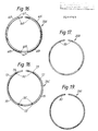
- the strip used to form a sleeve 25a has two elongate sections 65 which are pressed partly out of the plane of the strip.
- the sections are bent about edges 66 thereof.
- Each section has two transverse end edges 67 which terminate at stress relieving apertures 68.
- the sections 65 extend circumferentailly and form radially outwardly extending projecti ons having outer edges 69.
- the sleeve is located in groove 24 on the shaft 15 so that in order to reach the Fig.4 position, the ring must ride over the edges 69 by pressing sections 65 inwardly before finally snapping behind the projections as shown in Fig.11.
- edges 69 resist movement of the sleeve in direction A relative to the ring 20 which will assist in overcoming the jamming of the sleeve in the groove.
- sufficient load can be applied in direction A to the shaft 15 to cause the ring to press the sections 65 inwardly until it can ride over edges 60 and finally disengage the sleeve and shaft.
- the withdrawal of shaft 15 from within the hub 13 will cause the right hand side 22 of groove 19 to press the sections 65 inwardly to enable the sleeve to clear the hub.
- the strip is formed with two elongate apertures 70 into which the ring will snap when a sleeve 25B formed from the strip is in the Fig.4 position. The location of the ring in that way will again resist movement of the sleeve in direction A relative to the ring 20.
- Figs. 9,13 and 18 two elongate edge sections 72 are bent out of the plane of the strip.
- the sections 72 have end edges 73 which terminate at stress-relieving apertures 74.
- the sections 72 extend circumferentially and form radially outwardly extending projections having outer edges 75.
- the ring 20 In order to reach the Fig.4 position the ring 20 must ride over the edges 75 by pressing sections 72 inwardly before snapping behind the projections as shown in Fig.13.
- the sections 72 then act in similar manner to sections 65 in Fig.16.
- the strip is formed with an elongate groove 80 which locates the ring 20 in the Fig.4 position when bent into the form of a sleeve 25D and acts in a similar manner to the apertures 70 in Fig.8.
- both the detent ring 20 and the sleeves 25-25D are retained on their associated members 13,15 after disassembly.
- the hub 13 has a frusto conical lead-in surface 29 to aid assembly.
- a spring clip 30 is located around a cylindrical outer surface portion 32 of the shaft 15 in abutment with a shoulder 33 as described in G.B. No. 2176262A to limit movement of shaft 15 in direction B.
- the clip 30 si first removed using a suitable tool.
Landscapes
- Engineering & Computer Science (AREA)
- General Engineering & Computer Science (AREA)
- Mechanical Engineering (AREA)
- Mechanical Operated Clutches (AREA)
Applications Claiming Priority (2)
| Application Number | Priority Date | Filing Date | Title |
|---|---|---|---|
| GB868611221A GB8611221D0 (en) | 1986-05-08 | 1986-05-08 | Friction clutch |
| GB8611221 | 1986-05-08 |
Publications (2)
| Publication Number | Publication Date |
|---|---|
| EP0244989A2 true EP0244989A2 (de) | 1987-11-11 |
| EP0244989A3 EP0244989A3 (de) | 1988-05-18 |
Family
ID=10597513
Family Applications (1)
| Application Number | Title | Priority Date | Filing Date |
|---|---|---|---|
| EP87303576A Withdrawn EP0244989A3 (de) | 1986-05-08 | 1987-04-23 | Fahrzeugreibungskupplung |
Country Status (3)
| Country | Link |
|---|---|
| US (1) | US4858741A (de) |
| EP (1) | EP0244989A3 (de) |
| GB (1) | GB8611221D0 (de) |
Cited By (1)
| Publication number | Priority date | Publication date | Assignee | Title |
|---|---|---|---|---|
| GB2259345B (en) * | 1991-08-17 | 1996-02-07 | Luk Lamellen & Kupplungsbau | Clutch release apparatus |
Families Citing this family (4)
| Publication number | Priority date | Publication date | Assignee | Title |
|---|---|---|---|---|
| US4947975A (en) * | 1987-06-04 | 1990-08-14 | Kabushiki Kaisha Daikin Seisakusho | Release bearing mechanism of a clutch |
| JPH04105638U (ja) * | 1991-02-21 | 1992-09-11 | 株式会社大金製作所 | プルタイプクラツチ用レリーズ装置 |
| US5794752A (en) * | 1996-12-30 | 1998-08-18 | Dana Corporation | Clutch actuator |
| AU2004210951B2 (en) * | 2003-02-12 | 2009-07-09 | Ralph J. Koerner | Quilting method and apparatus |
Family Cites Families (7)
| Publication number | Priority date | Publication date | Assignee | Title |
|---|---|---|---|---|
| DE2639766C2 (de) * | 1976-09-03 | 1986-01-09 | LuK Lamellen und Kupplungsbau GmbH, 7580 Bühl | Reibungskupplungseinheit |
| DE3375191D1 (en) * | 1982-11-19 | 1988-02-11 | Automotive Prod Plc | A friction clutch for a vehicle |
| FR2544036B1 (fr) * | 1983-04-11 | 1988-10-28 | Valeo | Piece d'accostage a rapporter sur le diaphragme d'un embrayage, et ensemble unitaire constitue par un tel diaphragme et une telle piece d'accostage |
| FR2557234B1 (fr) * | 1983-12-27 | 1989-03-31 | Valeo | Montage de butee de debrayage, et butee de debrayage propre a un tel montage |
| EP0205320B1 (de) * | 1985-06-10 | 1989-11-02 | Automotive Products Public Limited Company | Reibungskupplung für Fahrzeug |
| FR2588338B1 (fr) * | 1985-10-09 | 1990-03-30 | Valeo | Montage de butee de debrayage reversible a organe de decouplage sur la butee de debrayage, notamment pour vehicule automobile |
| FR2588337B1 (fr) * | 1985-10-09 | 1990-02-02 | Valeo | Montage de butee de debrayage reversible, notamment pour vehicule automobile |
-
1986
- 1986-05-08 GB GB868611221A patent/GB8611221D0/en active Pending
-
1987
- 1987-04-23 EP EP87303576A patent/EP0244989A3/de not_active Withdrawn
- 1987-05-07 US US07/046,712 patent/US4858741A/en not_active Expired - Lifetime
Cited By (1)
| Publication number | Priority date | Publication date | Assignee | Title |
|---|---|---|---|---|
| GB2259345B (en) * | 1991-08-17 | 1996-02-07 | Luk Lamellen & Kupplungsbau | Clutch release apparatus |
Also Published As
| Publication number | Publication date |
|---|---|
| US4858741A (en) | 1989-08-22 |
| GB8611221D0 (en) | 1986-06-18 |
| EP0244989A3 (de) | 1988-05-18 |
Similar Documents
| Publication | Publication Date | Title |
|---|---|---|
| US4691815A (en) | Friction clutch and clutch release mechanism for a vehicle | |
| JP6457991B2 (ja) | 軸方向負荷を有するカートリッジフェルール | |
| EP0727027B1 (de) | Schnellkupplung mit einem integrierten entriegelungselement | |
| EP0663557B1 (de) | Verbesserungen an Rohrverbindungen | |
| US6840143B1 (en) | Adapter for screwdriver having elastic retainer ring | |
| WO1997048937A1 (en) | Snap-action pipe coupling retainer | |
| EP0205320B1 (de) | Reibungskupplung für Fahrzeug | |
| EP0244989A2 (de) | Fahrzeugreibungskupplung | |
| EP1072837A2 (de) | Rohrverbindung | |
| EP1248888A1 (de) | Vorrichtung zum verbinden von elementen | |
| US6390943B1 (en) | Retainer subassembly for and in combination with a master link for a chain | |
| EP0397695B1 (de) | Haltevorrichtung | |
| NZ215686A (en) | Expanding sleeve rivet: provision for removal and re-use | |
| JPH0629621B2 (ja) | クラツチ軸受装置 | |
| GB2193284A (en) | A friction clutch for a vehicle | |
| JPS62274118A (ja) | 結合装置 | |
| JP2000304020A (ja) | 固着装置及び固着方法 | |
| EP3630502B1 (de) | Modulare radendanordnung und installationsverfahren | |
| US2752805A (en) | Spring-nut applying tools | |
| GB2211264A (en) | A clutch release mechanism | |
| US4795280A (en) | Locking mechanism | |
| JPS6237522A (ja) | 車両用摩擦クラツチ | |
| GB2200707A (en) | Friction clutch release mechanism | |
| US4682680A (en) | Friction clutch with manually disconnectable release means | |
| GB2195413A (en) | A friction clutch for a vehicle |
Legal Events
| Date | Code | Title | Description |
|---|---|---|---|
| PUAI | Public reference made under article 153(3) epc to a published international application that has entered the european phase |
Free format text: ORIGINAL CODE: 0009012 |
|
| AK | Designated contracting states |
Kind code of ref document: A2 Designated state(s): DE FR GB IT |
|
| PUAL | Search report despatched |
Free format text: ORIGINAL CODE: 0009013 |
|
| AK | Designated contracting states |
Kind code of ref document: A3 Designated state(s): DE FR GB IT |
|
| 17P | Request for examination filed |
Effective date: 19881021 |
|
| 17Q | First examination report despatched |
Effective date: 19890317 |
|
| STAA | Information on the status of an ep patent application or granted ep patent |
Free format text: STATUS: THE APPLICATION IS DEEMED TO BE WITHDRAWN |
|
| 18D | Application deemed to be withdrawn |
Effective date: 19900522 |
|
| RIN1 | Information on inventor provided before grant (corrected) |
Inventor name: SYMONDS, DENZIL JOHN WILLIAMS Inventor name: BALL, ROBERT JOLYON Inventor name: MAYCOCK, IAN COMMANDER |