EP0245617B1 - Umluftherd - Google Patents
Umluftherd Download PDFInfo
- Publication number
- EP0245617B1 EP0245617B1 EP87103968A EP87103968A EP0245617B1 EP 0245617 B1 EP0245617 B1 EP 0245617B1 EP 87103968 A EP87103968 A EP 87103968A EP 87103968 A EP87103968 A EP 87103968A EP 0245617 B1 EP0245617 B1 EP 0245617B1
- Authority
- EP
- European Patent Office
- Prior art keywords
- air
- directing
- discharge holes
- plate
- cooking
- Prior art date
- Legal status (The legal status is an assumption and is not a legal conclusion. Google has not performed a legal analysis and makes no representation as to the accuracy of the status listed.)
- Expired
Links
- 238000010411 cooking Methods 0.000 title claims description 51
- 238000010438 heat treatment Methods 0.000 claims description 51
- 238000007599 discharging Methods 0.000 claims description 2
- 230000001154 acute effect Effects 0.000 description 1
- 238000010276 construction Methods 0.000 description 1
- 230000000694 effects Effects 0.000 description 1
- 230000004048 modification Effects 0.000 description 1
- 238000012986 modification Methods 0.000 description 1
Images

Classifications
-
- F—MECHANICAL ENGINEERING; LIGHTING; HEATING; WEAPONS; BLASTING
- F24—HEATING; RANGES; VENTILATING
- F24C—DOMESTIC STOVES OR RANGES ; DETAILS OF DOMESTIC STOVES OR RANGES, OF GENERAL APPLICATION
- F24C15/00—Details
- F24C15/32—Arrangements of ducts for hot gases, e.g. in or around baking ovens
- F24C15/322—Arrangements of ducts for hot gases, e.g. in or around baking ovens with forced circulation
- F24C15/325—Arrangements of ducts for hot gases, e.g. in or around baking ovens with forced circulation electrically-heated
Definitions
- This invention relates to a hot-air circulation cooking oven for cooking food within a heating chamber by circulating hot air within the chamber with the use of a fan as it is disclosed in EP-A-0023827.
- a hot-air circulation cooking oven has an inner casing defining a heating chamber for storing a cooking tray at its center and a pan-like cover attached to the rear plate of the inner casing to define a fan chamber in which a hot air circulation fan and heater are provided.
- a number of suction holes are cut, as punched holes, in the center portion of the rear plate.
- a number of upper discharge holes and of lower discharge holes are cut in the upper and lower portions of the rear plate, above and below the suction holes.
- the upper and lower discharge holes are formed in a band-like array extending in the horizontal direction.
- the fan is arranged opposite to the suction holes and driven by a motor which is provided external to the cover.
- a heater is ring-like in configuration and provided around the fan.
- the hot air has to be circulated up to the region remote from the discharge holes, i.e., up to the neighborhood of the door in front of the heating chamber.
- the portion facing the discharge holes is inclined toward the heating chamber.
- the hot air from the fan is directed by the inclination portion toward the heating chamber and sent toward the neighborhood of the door far distant from the discharge holes.
- the hot air can be circulated from the discharge holes into a zone far from the discharge holes.
- the hot air is more strongly blown over the food item on the cooking tray as situated on the door side than the food item on the same cooking tray as situated on the discharge hole side. This causes the food items set one behind another on the same tray to be unevenly browned within the heating chamber.
- the suction holes and discharge holes are provided adjacent to one another in the cooking oven, part of the hot air, which is discharged from the discharge holes, is short-circuited, thus causing it to blow from the suction holes directly into the fan chamber without being circulated through the heating chamber.
- the hot air cannot be effectively used in heating the food items and the heat quantity is not adequately applied to the zone distant from the discharge holes, resulting in the uneven heating of the food items.
- the hot air impinging on the bottom of the upper tray is causing a faster cooking of the food thereon than the food on the lower tray which is exposed to a hot air stream with less temperature.
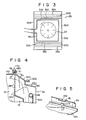
- Figs. 1 to 5 show a cooking oven according to a first embodiment of the invention, in which
- a hot-air circulation cooking oven includes outer casing 10 and inner casing 12 located within the outer casing and defining heating chamber 14.
- Casing 12 is box-like in configuration and has top plate 12a, bottom plate 12b and side plates 12c to 12e with access opening 16 located at the front side. Access to food within heating chamber 14 is gained by opening and closing door 18 which is attached to outer casing 10.
- a pair of support rails 20, 20 are formed on the inner surface of each of side plates 12d and 12e, and extend in the horizontal direction. Upper and lower cooking trays 22a and 22b are supported by corresponding support rails 20, 20 within heating chamber 14. Rails 20, 20 are so arranged that an equal internal is defined between top plate 12a of casing 12 and cooking tray 22a, between cooking trays 22a and 22b, and between cooking tray 22b and bottom plate 12b.
- substantially rectangular recess 15 is formed by "drawing” such that it projects outwardly of the casing.
- a plurality of punched holes are formed as suction holes 24 and distributed in a rectangular pattern.
- Suction holes 24 are formed at a location corresponding to the space between cooking trays 22a and 22b.
- a number of upper discharge holes 26 are formed in side plate 12c of casing 12 at a location situated above suction holes. 24, or recess 15, whereas a number of lower discharge holes 28 are formed in side plate 12c of casing 12 at a location situated below recess 15.
- Upper exhaust holes 26 are arranged in a rectangular pattern across a substantially whole width of side plate 12c and situated at a location corresponding to the space defined between top wall 12a of casing 12 and upper cooking tray 22a.
- Lower discharge holes 28 are arranged in a rectangular pattern across a substantially whole width of side plate 12c and situated at a location corresponding to the space between lower cooking tray 22b and bottom plate 12b of casing 12.
- Cover 30 is a rectangular pan-like in configuration and fixed to the outer surface of rear plate 12c to define storing chamber 31 therebetween. Storing chamber 31 communicates with heating chamber 14 through suction hole 24 and discharge holes 26, 28.
- cover 30 has bottom plate 30a facing rear plate 12c, upper and lower plates 30b and 30c slantly extending across the whole width of heating chamber 14, and a pair of vertically extending side plates 30d, 30d.
- Upper and lower plates 30b and 30c are located opposite to upper and lower discharge holes 26 and 28, respectively.
- Upper plate 30b has first air-directing section 32a located on the side of top plate 12a, vertically extending shoulder 32b and second air-directing section 32c extending from shoulder 32b to bottom plate 30a.
- First air-directing section 32a is inclined at angle (an acute angle) 81 with respect to top plate 12a, i.e., a horizontal plane
- second air-directing section 32c is inclined at an angle equal to, or smaller than, the angle 91 of first air-directing section 32a with respect to a horizontal plane.
- lower plate 30c has first air-directing section 33a, shoulder 33b and second air-directing section 33c.
- fan 34 In storing chamber 31 are arranged fan 34 facing suction holes 24 and substantially ring-like electric heater 36 located around the outer periphery of fan 34. Fan 34 is rotated in a predetermined direction i.e., in a counterclockwise direction, by means of motor 38 which is provided outwardly of cover 30.
- top plate 12a of casing 12 is bent upward at the rear end portion to form bent section 17.
- the middle portion of bent section 17 further projects upward, thereby forming an engaging piece 17a.
- Latching member 19 with engaging hole 19a extends from the upper end of cover 30 in a direction of casing 12.
- Cover 30 is securely fixed by screw 21 to casing 12 with engaging piece 17a inserted into engaging hole 19a.
- cover 30 can readily be positioned relative to casing 12 by means of a combination of engaging piece 17a and latching member 19.
- reference numeral 46 represents a motor.
- Rotation shaft 46a of motor 46 extends into heating chamber 14 through bottom plate 12b of casing 12. With cooking trays 22a and 22b not in use, a turntable (not shown) is placed in engagement with rotation shaft 46a within heating chamber 14 such that it may be rotated by motor 46.
- the cooking oven is equipped with a magnetron (not shown) and can be used as a microwave oven.
- upper and lower cooking trays 22a and 22b are set within heating chamber 14 through access opening 16 and, upon closing door 18, motor 38 and heater 36 are operated by actuating the operation section, not shown.
- motor 38 When fan 34 is rotated by motor 38, air between cooking trays 22a and 22b within heating chamber 14 is sucked from suction holes 24 into storing chamber 32. The sucked air, while being agitated in a vortex by the rotation of fan 34, is blown outwardly, at which time it is heated by heater 36 and becomes hot air.
- first and second air-directing sections 32a and 32c of upper plate 30a are inclined at different angles and hence the hot air abutting the upper plate is divided into two streams: a stream along the first air-directing section and stream along the second air-directing section.
- the hot air abutting first air-directing section 32a is discharged in a direction substantially parallel to top plate 12a of casing 12 from discharge hole 26 and flows to that zone in the neighborhood of door 18.
- the hot air abutting second air-directing section 32c is discharged in a direction different from that of the hot air hit against first air-directing section 32a, i.e., into a zone in the neighborhood of discharge holes 26 within heating chamber 14.
- the hot air hitting against first-directing section 33a is discharged toward a zone in the neighborhood of door 18 within heating chamber 14, and the hot air hitting against second air-directing section 33c is discharged toward a zone in the neighborhood of discharge hole 28.
- the food items placed on the tray within heating chamber 14 are cooked by the hot air discharged.
- the hot air is uniformly discharged everywhere into the heating chamber from the discharge holes.
- the food item near the door and food item near the discharge holes can be substantially uniformly heated in a better balance within the heating chamber. Therefore, there is no possibility that some of food items will be locally intensely heated within the heating chamber. It is, therefore, possible to prevent the food items one behind another on the same tray from being unevenly browned.
- the uneven browning of the food items on the upper tray is markedly improved due to the hot air from the upper discharge holes directly hitting the food items on the upper tray.
- the food items which are placed one behind another on the lower tray are uniformly heated through the cooking tray and browned in better condition.
- the suction holes are formed in the recess bottom wall which projects outwardly from the casing, and adequately spaced from the discharge holes. Therefore, the hot air discharged into the heating chamber through the discharge holes always flows through the suction holes into the fan chamber after it has been circulated within the heating chamber, without being flowed directly toward the suction holes. Thus, all the air discharged from the discharge holes can effectively be utilized to heat the food in the heating chamber, and discharged into the whole heating chamber so that the food in the heating chamber can be uniformly heated. Furthermore, a greater space can be secured within a heating chamber due to the presence of the recess. Thus, many items of food can be cooked at a time since it is possible to place, within the heating chamber, cooking trays of larger size which would have so far been unable to be held within the heating chamber.
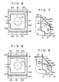
- the second air-directing section is formed of the upper plate or the lower plate of the cover.
- the second air-directing section may be formed by an air-directing plate separate from the cover.
- upper and lower plates 30b and 30c of cover 30 constitute first air-directing sections 32a and 33a, respectively.
- Second air-directing section 32c is formed of air-directing plate 42 which is fixed to bottom plate 30 along the edge of first air-directing section 32a. Air-directing plate 42 extends across the whole width of cover 30 and is inclined at an angle of 92 (B2 5 _ 0 1) to a horizontal.
- second air-directing section 33c is formed of air-directing plate 44 which is fixed to bottom plate 30a of cover 30 along the edge of first air-directing section 33a.
- Air-directing plate 44 extends across the whole width of cover 30 and is inclined at an angle, smaller than the inclination angle of first air-directing section 33a, with respect to the horizontal.
- air-directing plates 42 and 44 may have a plurality of punched holes as shown in Figs. 8 and 9.
- any possible unbalance in the amounts of hot air discharged into the left and right zones around the cooking tray within the heating chamber can be improved by the straightening effect of the punched holes.
- the left- right unbalance though depending upon the capability of the heater, diameter of the fan, number of rotations of the fan, and so on, can be much improved by selecting the length of the air-directing plate, diameter and pitch of the punched holes, etc.
- the number of the second air-directing sections can be increased as required. An increased number of the second air-directing sections allows the hot air to be finely controlled in their discharging directions.
- the cover for defining the storing chamber though being provided at the rear plate of the inner casing, may be fixed to any other side plate of the inner casing.
Landscapes
- Engineering & Computer Science (AREA)
- Chemical & Material Sciences (AREA)
- Combustion & Propulsion (AREA)
- Mechanical Engineering (AREA)
- General Engineering & Computer Science (AREA)
- Electric Stoves And Ranges (AREA)
- Baking, Grill, Roasting (AREA)
Claims (6)
dadurch gekennzeichnet, daß
Applications Claiming Priority (6)
| Application Number | Priority Date | Filing Date | Title |
|---|---|---|---|
| JP111112/86 | 1986-05-15 | ||
| JP11111286A JPS62268921A (ja) | 1986-05-15 | 1986-05-15 | 熱風循環式調理器 |
| JP1986076553U JPH0438161Y2 (de) | 1986-05-21 | 1986-05-21 | |
| JP76553/86U | 1986-05-21 | ||
| JP79456/86U | 1986-05-26 | ||
| JP7945686U JPS62192119U (de) | 1986-05-26 | 1986-05-26 |
Publications (4)
| Publication Number | Publication Date |
|---|---|
| EP0245617A2 EP0245617A2 (de) | 1987-11-19 |
| EP0245617A3 EP0245617A3 (en) | 1989-02-22 |
| EP0245617B1 true EP0245617B1 (de) | 1991-07-24 |
| EP0245617B2 EP0245617B2 (de) | 1994-03-23 |
Family
ID=27302189
Family Applications (1)
| Application Number | Title | Priority Date | Filing Date |
|---|---|---|---|
| EP87103968A Expired - Lifetime EP0245617B2 (de) | 1986-05-15 | 1987-03-18 | Umluftherd |
Country Status (3)
| Country | Link |
|---|---|
| US (1) | US4780596A (de) |
| EP (1) | EP0245617B2 (de) |
| DE (1) | DE3771566D1 (de) |
Families Citing this family (34)
| Publication number | Priority date | Publication date | Assignee | Title |
|---|---|---|---|---|
| FR2623883B1 (fr) * | 1987-11-27 | 1991-05-10 | Seb Sa | Four de cuisson electrique a ventilation |
| US4908488A (en) * | 1988-07-22 | 1990-03-13 | Samsung Electronics Co., Ltd. | Fixing device of a heating member in a combined microwave and convection cooking apparatus |
| NL9001472A (nl) * | 1990-06-27 | 1992-01-16 | Fri Jado Bv | Toestel voor het bereiden van vlees of dergelijke waar. |
| US5285719A (en) * | 1992-09-11 | 1994-02-15 | Gas Research Institute | Rapid frozen food thawing system |
| US5361686A (en) * | 1992-11-10 | 1994-11-08 | Henny Penny Corporation | Rotisserie oven |
| US5451744A (en) * | 1992-11-10 | 1995-09-19 | Henny Penny Corporation | Rotisserie oven |
| US5445061A (en) * | 1992-12-16 | 1995-08-29 | Barradas; George | Combination bread making machine and cooker |
| US5458050A (en) * | 1993-03-01 | 1995-10-17 | Su; Johnson | Multi-purpose cooker |
| US5336867A (en) * | 1993-12-13 | 1994-08-09 | General Electric Company | Convection oven tapered air heating chamber |
| US5423249A (en) * | 1994-01-12 | 1995-06-13 | American Harvest, Inc. | Food dehydrator |
| US5756974A (en) * | 1995-06-09 | 1998-05-26 | Samsung Electronics Co., Ltd. | Convection microwave oven having improved hot air circulation |
| US5601070A (en) * | 1996-06-17 | 1997-02-11 | Middleby Marshall, Inc. | Convection oven |
| US6085442A (en) * | 1997-01-10 | 2000-07-11 | The Metal Ware Corporation | Food Dehydrator |
| US5786567A (en) * | 1997-01-30 | 1998-07-28 | Wang; Ching-Hsiang | Oven |
| US6069344A (en) * | 1999-01-27 | 2000-05-30 | Hp Intellectual Corp. | Convection feature for use in ovens |
| US6124572A (en) * | 1999-09-21 | 2000-09-26 | Spilger; Jon Barton | Food warmer cabinet having an improved drawer slide assembly |
| KR100399130B1 (ko) * | 1999-11-17 | 2003-09-26 | 삼성전자주식회사 | 전자렌지 |
| EP1109425B1 (de) | 1999-12-17 | 2013-10-30 | LG Electronics, Inc. | Effiziente Zuführung von erzeugter Hitze durch einen Heizer, der in dem elektronischen Küchenherd eingebaut ist |
| DE10314571A1 (de) * | 2003-03-31 | 2004-10-14 | BSH Bosch und Siemens Hausgeräte GmbH | Gargerät |
| JP3701295B2 (ja) * | 2003-05-15 | 2005-09-28 | シャープ株式会社 | 加熱調理器 |
| DE20309268U1 (de) * | 2003-06-12 | 2004-06-09 | Rational Ag | Gargeräte mit Luftleitgliedern |
| KR101013376B1 (ko) † | 2003-12-10 | 2011-02-14 | 삼성전자주식회사 | 조리 장치 및 그 제어 방법 |
| KR100876463B1 (ko) * | 2003-12-30 | 2008-12-31 | 아세릭 에이. 에스 | 오븐 |
| US6802247B1 (en) * | 2004-02-02 | 2004-10-12 | Ming-Tsung Lee | Electric oven |
| JP3835804B2 (ja) * | 2004-02-10 | 2006-10-18 | 松下電器産業株式会社 | 加熱調理器及び加熱調理方法 |
| US6872926B1 (en) * | 2004-02-25 | 2005-03-29 | Maytag Corporation | Rapid cook oven with dual flow fan assembly |
| EP2408263B1 (de) | 2004-12-14 | 2014-02-12 | Enodis Corporation | Umwälzungs-/Konvektions-/Mikrowellenofen und Verfahren |
| KR100889132B1 (ko) * | 2007-04-12 | 2009-03-17 | 엘지전자 주식회사 | 오븐 |
| DE102008053145A1 (de) * | 2008-10-24 | 2010-04-29 | Rational Ag | Strömungsleitvorrichtung für ein Gargerät |
| EP2636955B1 (de) * | 2012-03-08 | 2016-11-16 | Electrolux Home Products Corporation N.V. | Kochherd für Wärmeübertragung durch Konvektion |
| KR101577497B1 (ko) * | 2013-04-30 | 2015-12-14 | 동부대우전자 주식회사 | 조리장치 |
| CN105940267B (zh) * | 2014-02-05 | 2018-04-24 | 松下知识产权经营株式会社 | 加热烹调器 |
| US10794601B1 (en) * | 2016-10-14 | 2020-10-06 | Fastform Research Ltd. | Adjustable convective heat chamber apparatus and method of use |
| CN112244657B (zh) * | 2020-09-14 | 2022-04-05 | 华帝股份有限公司 | 一种烹饪设备及其控制方法 |
Family Cites Families (12)
| Publication number | Priority date | Publication date | Assignee | Title |
|---|---|---|---|---|
| US2906620A (en) * | 1956-02-21 | 1959-09-29 | Burger Eisenwerke Gmbh | Method of de-freezing and heating deep-frozen foods |
| US3324844A (en) * | 1965-11-09 | 1967-06-13 | Vulcan Hart Corp | Heat distribution system for gas-fired ovens |
| US4068572A (en) * | 1972-01-31 | 1978-01-17 | Hans Vogt | Apparatus for heating food |
| JPS53136572A (en) * | 1977-05-02 | 1978-11-29 | Matsushita Electric Industrial Co Ltd | Electric oven |
| JPS55165428A (en) * | 1979-06-09 | 1980-12-23 | Toshiba Corp | Oven |
| JPS5950890B2 (ja) * | 1979-06-25 | 1984-12-11 | 株式会社東芝 | 加熱装置 |
| GB2070907B (en) * | 1979-07-27 | 1984-05-10 | Matsushita Electric Industrial Co Ltd | Heating cooking device |
| US4337384A (en) * | 1979-08-01 | 1982-06-29 | Matsushita Electric Industrial Co., Ltd. | Cooking appliance of the hot air circulating type |
| FI61765C (fi) * | 1980-11-10 | 1982-09-10 | Orion Yhtymae Oy | Luftcirkulationssystem foer en gaskromatografugn |
| JPS5835927A (ja) * | 1981-08-28 | 1983-03-02 | Fujitsu Ltd | 半導体装置の製造方法 |
| US4627409A (en) * | 1982-04-14 | 1986-12-09 | Matsushita Electric Industrial Co., Ltd. | Cooking appliance of hot air circulation type |
| US4462383A (en) * | 1982-06-09 | 1984-07-31 | Lincoln Manufacturing Company, Inc. | Impingement food preparation apparatus |
-
1987
- 1987-03-17 US US07/026,997 patent/US4780596A/en not_active Expired - Fee Related
- 1987-03-18 DE DE8787103968T patent/DE3771566D1/de not_active Expired - Lifetime
- 1987-03-18 EP EP87103968A patent/EP0245617B2/de not_active Expired - Lifetime
Also Published As
| Publication number | Publication date |
|---|---|
| DE3771566D1 (de) | 1991-08-29 |
| EP0245617A2 (de) | 1987-11-19 |
| US4780596A (en) | 1988-10-25 |
| EP0245617A3 (en) | 1989-02-22 |
| EP0245617B2 (de) | 1994-03-23 |
Similar Documents
| Publication | Publication Date | Title |
|---|---|---|
| EP0245617B1 (de) | Umluftherd | |
| US5798505A (en) | Microwave oven with upwardly directed air discharge duct | |
| JP3939299B2 (ja) | 加熱調理器 | |
| EP0245618B1 (de) | Umluftherd | |
| US4484063A (en) | Convection oven | |
| US7102105B2 (en) | Electric oven | |
| EP1780471B1 (de) | Gargerät | |
| US7368683B2 (en) | Convection chamber of cooking device | |
| JPS6313091B2 (de) | ||
| JPH02162683A (ja) | 二重目的オーブン | |
| EP1586820B1 (de) | Kühlvorrichtung für Backgerät | |
| US6218651B1 (en) | Microwave oven | |
| US5726429A (en) | Protective cover for a convection microwave oven | |
| US6689991B2 (en) | Electronic range | |
| US8546735B2 (en) | Microwave oven | |
| US20070107712A1 (en) | Heating cooker | |
| JPH08247473A (ja) | 加熱調理器 | |
| US7271373B2 (en) | Microwave oven | |
| JPH07111256B2 (ja) | 熱風循環式調理器 | |
| US5336867A (en) | Convection oven tapered air heating chamber | |
| CA1148815A (en) | Convection oven | |
| JPH0132408B2 (de) | ||
| KR0113760Y1 (ko) | 다기능 전자렌지의 냉각장치 | |
| KR900009526Y1 (ko) | 열풍 순환형 오븐 레인지 | |
| JP2000039153A (ja) | 加熱調理器 |
Legal Events
| Date | Code | Title | Description |
|---|---|---|---|
| PUAI | Public reference made under article 153(3) epc to a published international application that has entered the european phase |
Free format text: ORIGINAL CODE: 0009012 |
|
| 17P | Request for examination filed |
Effective date: 19870415 |
|
| AK | Designated contracting states |
Kind code of ref document: A2 Designated state(s): DE FR GB |
|
| PUAL | Search report despatched |
Free format text: ORIGINAL CODE: 0009013 |
|
| AK | Designated contracting states |
Kind code of ref document: A3 Designated state(s): DE FR GB |
|
| 17Q | First examination report despatched |
Effective date: 19900312 |
|
| GRAA | (expected) grant |
Free format text: ORIGINAL CODE: 0009210 |
|
| AK | Designated contracting states |
Kind code of ref document: B1 Designated state(s): DE FR GB |
|
| REF | Corresponds to: |
Ref document number: 3771566 Country of ref document: DE Date of ref document: 19910829 |
|
| ET | Fr: translation filed | ||
| PLBI | Opposition filed |
Free format text: ORIGINAL CODE: 0009260 |
|
| 26 | Opposition filed |
Opponent name: BOSCH-SIEMENS HAUSGERAETE GMBH, MUENCHEN Effective date: 19920424 |
|
| PUAH | Patent maintained in amended form |
Free format text: ORIGINAL CODE: 0009272 |
|
| STAA | Information on the status of an ep patent application or granted ep patent |
Free format text: STATUS: PATENT MAINTAINED AS AMENDED |
|
| 27A | Patent maintained in amended form |
Effective date: 19940323 |
|
| AK | Designated contracting states |
Kind code of ref document: B2 Designated state(s): DE FR GB |
|
| ET3 | Fr: translation filed ** decision concerning opposition | ||
| PGFP | Annual fee paid to national office [announced via postgrant information from national office to epo] |
Ref country code: GB Payment date: 19980309 Year of fee payment: 12 |
|
| PGFP | Annual fee paid to national office [announced via postgrant information from national office to epo] |
Ref country code: FR Payment date: 19980310 Year of fee payment: 12 |
|
| PGFP | Annual fee paid to national office [announced via postgrant information from national office to epo] |
Ref country code: DE Payment date: 19980327 Year of fee payment: 12 |
|
| PG25 | Lapsed in a contracting state [announced via postgrant information from national office to epo] |
Ref country code: GB Free format text: LAPSE BECAUSE OF NON-PAYMENT OF DUE FEES Effective date: 19990318 |
|
| GBPC | Gb: european patent ceased through non-payment of renewal fee |
Effective date: 19990318 |
|
| PG25 | Lapsed in a contracting state [announced via postgrant information from national office to epo] |
Ref country code: FR Free format text: LAPSE BECAUSE OF NON-PAYMENT OF DUE FEES Effective date: 19991130 |
|
| REG | Reference to a national code |
Ref country code: FR Ref legal event code: ST |
|
| PG25 | Lapsed in a contracting state [announced via postgrant information from national office to epo] |
Ref country code: DE Free format text: LAPSE BECAUSE OF NON-PAYMENT OF DUE FEES Effective date: 20000101 |