EP0245676A1 - Porte pliante, notamment pour ascenseurs - Google Patents
Porte pliante, notamment pour ascenseurs Download PDFInfo
- Publication number
- EP0245676A1 EP0245676A1 EP87105966A EP87105966A EP0245676A1 EP 0245676 A1 EP0245676 A1 EP 0245676A1 EP 87105966 A EP87105966 A EP 87105966A EP 87105966 A EP87105966 A EP 87105966A EP 0245676 A1 EP0245676 A1 EP 0245676A1
- Authority
- EP
- European Patent Office
- Prior art keywords
- leaf
- axis
- central part
- leaves
- symmetry
- Prior art date
- Legal status (The legal status is an assumption and is not a legal conclusion. Google has not performed a legal analysis and makes no representation as to the accuracy of the status listed.)
- Granted
Links
- 238000005304 joining Methods 0.000 claims description 2
- 238000010276 construction Methods 0.000 description 5
- 239000002184 metal Substances 0.000 description 3
- 230000000295 complement effect Effects 0.000 description 2
- 238000004519 manufacturing process Methods 0.000 description 2
- 238000000034 method Methods 0.000 description 2
- 239000000725 suspension Substances 0.000 description 2
- 238000003466 welding Methods 0.000 description 2
- 238000003754 machining Methods 0.000 description 1
- 238000000465 moulding Methods 0.000 description 1
- 238000003825 pressing Methods 0.000 description 1
Images
Classifications
-
- A—HUMAN NECESSITIES
- A62—LIFE-SAVING; FIRE-FIGHTING
- A62C—FIRE-FIGHTING
- A62C2/00—Fire prevention or containment
- A62C2/06—Physical fire-barriers
- A62C2/12—Hinged dampers
- A62C2/14—Hinged dampers with two or more blades
- A62C2/16—Hinged dampers with two or more blades multi-vane roll or fold-up type
-
- E—FIXED CONSTRUCTIONS
- E06—DOORS, WINDOWS, SHUTTERS, OR ROLLER BLINDS IN GENERAL; LADDERS
- E06B—FIXED OR MOVABLE CLOSURES FOR OPENINGS IN BUILDINGS, VEHICLES, FENCES OR LIKE ENCLOSURES IN GENERAL, e.g. DOORS, WINDOWS, BLINDS, GATES
- E06B3/00—Window sashes, door leaves, or like elements for closing wall or like openings; Layout of fixed or moving closures, e.g. windows in wall or like openings; Features of rigidly-mounted outer frames relating to the mounting of wing frames
- E06B3/32—Arrangements of wings characterised by the manner of movement; Arrangements of movable wings in openings; Features of wings or frames relating solely to the manner of movement of the wing
- E06B3/48—Wings connected at their edges, e.g. foldable wings
- E06B3/481—Wings foldable in a zig-zag manner or bi-fold wings
Definitions
- the invention relates to a folding door, in particular for elevators, of the type comprising at least one pair of hinged connected leaves, one after the other by means of articulation elements forming a hinge part provided on the sides. longitudinal of each leaf.
- folding doors are that they can be zigzagged. Therefore, during the opening operation, they require neither a rectilinear removal of the leaves laterally to the door bay nor a curvilinear withdrawal followed by a rectilinear withdrawal of the leaves for an arrangement perpendicular to the bay of the door.
- a folding door for elevators using a plurality of connected panels hinged one after the other is shown in French Patent No. 848,046.
- each leaf is however hinged to one of the stakes of a folding lattice construction circulating in a guide rail.
- the disadvantage of such a solution lies in the fact that, during the closing operation, the stakes of the folding lattice construction are placed one after the other along the guide rail, this which results in occupying a considerable place.
- French patent No. 1,025,073, particularly with reference to FIGS. 5 and 6, further discloses a folding door made up of a succession of flat sheet metal panels, hinged one after the other via hinge elements fixed by welding to the longitudinal sides of the panels.
- This door foldable in a zigzag, has the advantage of occupying relatively little space in the open position.
- the flat sheet metal panels offer little rigidity, and such a folding door would hardly be suitable for use in an elevator.
- a violent impact - or even a frontal push - to which one of the panels would be subjected could indeed cause a veiling, or even a permanent deformation of the panel, and could risk having disastrous consequences on the operation during the opening operations or door closing, this that it is a cabin door or a landing door.
- leaves having a relatively large thickness for example wooden leaves or leaves in the form of metal boxes.
- Rigid leaves, having a certain thickness are for example represented in the Swiss patents n ° 330 971 and German n ° 1 183 830 which both relate to elevator doors with central opening made up of two pairs of separate leaves respectively foldable, in the open position, alongside the door opening.
- the already large space required by each pair of leaves would not, however, make it possible to envisage a folding door construction comprising several pairs of such relatively thick leaves accumulated on only one side of the door opening, and even less on both sides of that -this.
- the object of the present invention is to remedy the drawbacks of these known constructions.
- it makes it possible to provide a solution to the problem which consists in creating a folding door, in particular a door for lifts, the leaves of which can both have good rigidity and occupy a minimum space when the door is folded in the open position.
- a folding door having the aforementioned characteristics can be constructed from a single type of leaf of relatively simple manufacture whose particular profile, on the one hand, ensures the leaf excellent rigidity and, on the other hand, allows the leaves to be nestable during the opening operation, which significantly reduces the space occupied by the leaves. Therefore, a folding door construction in a single foldable part on one side of the door opening or in two foldable parts on both sides of the door and provided with two or more pairs of leaves for each part can easily be considered.
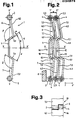
- the reference 1 designates, shown in top view, one of the leaves 1A, 1B, 1C, 1D of a folding elevator door with two pairs of leaves shown in the folded position in FIG. 2.
- the references 2 and 3 designate articulation elements of tubular shape respectively disposed on the two longitudinal sides of the leaf 1.
- the hinge elements 2 provided on one side of the leaf 1 are complementary to the hinge elements 3 provided on the other side and thus constitute hinge parts in which can be engaged cylindrical rods 4 forming axes of joint.
- FIG. 3 which partially shows, from the front and deployed, two of the leaves 1A, 1B hinged together from the folding door shown in FIG. 2.
- the reference xx ' represents for leaf 1 an axis of symmetry which extends perpendicularly to a line designated by YY' passing through the axes of the opposite articulation elements 2 and 3 provided on the two longitudinal sides of leaf 1.
- the reference 5 designates a central part of the leaf 1 which, in profile, consists of a rectilinear core disposed along the axis of symmetry XX 'and extending parallel to the line YY' passing through the axes of the articulation elements 2 and 3, l 'one of its faces being practically placed in the plane of the line YY '.
- the leaf 1 comprises in profile a wing 6, 7 which connects the central part 5 to the respective articulation elements 2, 3.
- Each wing 6, 7 consists of two branches 6.1, 6.2; 7.1, 7.2 forming between them an angle greater than 90 ° which, for each wing 6, 7, is of the same size and is oriented in the same direction.
- the branch 6.1, 7.1 adjacent to the central part 5 is of the same length and, from the central part 5, it departs from the axis of symmetry XX ', the angle y formed by l 'one of the branches 6.1 relative to the axis of symmetry XX' being greater than the angle formé formed by the other branch 7.1.
- the leaf 1, preferably metallic, thus constitutes a profiled element which has good rigidity and has a certain asymmetry with respect to the axis XX '.
- the central part 5 of the leaf 1 and its two lateral wings 6 and 7 can, for example, be obtained by pressing and the articulation elements 2 and 3 can be added by welding, but the complete leaf 1 can also be obtained from 'Other manufacturing techniques such as by profiling, with special machining for the complementary articulation elements 2 and 3, or by pressure molding.
- the folding elevator door shown in the folded position in Figure 2, has two pairs of leaves 1 of the type represented in FIG. 1.
- the reference 8 indicates, diagrammatically, one of the uprights of an elevator car to which the first leaf 1A of the four leaves 1A, 1B, 1C, 1D constituting the folding door is articulated by the intermediate of one of the cylindrical rods 4 forming an axis of articulation.
- the four leaves 1A, 1B, 1C, 1D are connected hinged one after the other also by means of cylindrical rods 4.
- the door is folded during the opening operation and deployed during the operation closing by translational movements carried out perpendicular to the upright 8 of the cabin, in the direction of the arrows F and F 'respectively.
- the door can, for example, be suspended from a guide rail arranged at the upper part of the cabin by means of rollers mounted on an extension of the last two cylindrical rods 4.
- the same cylindrical rods 4 can be provided with rollers circulating in a guide rail arranged in the floor of the cabin.
- rollers which, like the door drive device, are well known in the elevator technique for the suspension, guiding and driving of landing doors and / or cabins have not been shown.
- a mode of suspension and guidance folding door of the kind is also shown in French patent n 0 1 025 073 cited above.
- Figure 2 shows that, during the assembly of the joints which allow the leaves 1 to extend one after the other once the folding door deployed in the closed position, the second leaf 1B, 1D of each pair of leaves has been, on the one hand, rotated 180 ° around its longitudinal axis and, on the other hand, rotated 180 ° around its axis of symmetry XX 'relative to the first leaf 1A, 1C. From a single model of leaf 1, it is thus possible to provide a folding door whose leaves can have a rigidity which is close to that of the boxes and fit into one another, so that all the leaves occupy a minimum space once the door is folded into the open position.
- the leaf 1 whose profile, in particular of the central part, could have other shapes than those shown, the condition being that the central part is arranged along the axis of symmetry XX 'of the leaf and that a certain asymmetry exists between the two wings connecting the central part to the articulation elements.
- the branches of the wings adjacent to the central part could be provided so as to be connected on the axis of symmetry. In this case, the central part would merge with the axis of symmetry.
Landscapes
- Health & Medical Sciences (AREA)
- Public Health (AREA)
- Business, Economics & Management (AREA)
- Emergency Management (AREA)
- Engineering & Computer Science (AREA)
- Civil Engineering (AREA)
- Structural Engineering (AREA)
- Extensible Doors And Revolving Doors (AREA)
- Elevator Door Apparatuses (AREA)
- Securing Of Glass Panes Or The Like (AREA)
Abstract
Description
- L'invention concerne une porte pliante, notamment pour ascenseurs, du type comportant au moins une paire de vantaux reliés articulés l'un à la suite de l'autre par l'intermédiaire d'éléments d'articulation formant partie de charnière prévus aux côtés longitudinaux de chaque vantail.
- De telles portes pliantes ont l'avantage de pouvoir être pliées en zigzag. De ce fait, lors de l'opération d'ouverture, elles n'exigent ni un retrait rectiligne des vantaux latéralement à la baie de la porte ni un retrait curviligne suivi d'un retrait rectiligne des vantaux pour une disposition perpendiculaire à la baie de la porte.
- Une porte pliante pour ascenseurs faisant appel à une pluralité de panneaux reliés articulés l'un à la suite de l'autre est montrée dans le brevet français n° 848 046.
- Dans cette porte pliante, chaque vantail est cependant relié par charnière à l'un des piquets d'une construction pliante en treillis circulant dans un rail de guidage. Le désavantage d'une telle solution réside dans le fait que, lors de l'opération de fermeture, les piquets de la construction pliante en treillis viennent se placer l'un à la suite de l'autre au long du rail de guidage, ce qui a pour résultat d'occuper une place considérable.
- Le brevet français n° 1 025 073, particulièrement en référence aux figures 5 et 6, révèle par ailleurs une porte pliante constituée d'une succession de panneaux en tôle plane, articulés l'un à la suite de l'autre par l'intermédiaire d'éléments formant charnière fixés par soudage aux côtés longitudinaux des panneaux. Cette porte, pliable en zigzag, a l'avantage d'occuper relativement peu de place en position d'ouverture. Toutefois, les panneaux en tôle plane n'offrent que peu de rigidité, et une telle porte pliante ne conviendrait guère pour une utilisation dans un ascenseur. Un choc violent - ou même une poussée frontale - auquel serait soumis l'un des panneaux pourrait en effet provoquer un voilage, voire une déformation permanente du panneau, et risquerait d'avoir des conséquences désastreuses sur le fonctionnement lors des opérations d'ouverture ou de fermeture de la porte, ceci que cette dernière soit une porte de cabine ou une porte palière.
- Il est possible de compenser ce manque de rigidité par l'utilisation de vantaux disposant d'une épaisseur relativement importante, par exemple des vantaux en bois ou des vantaux en forme de caissons métalliques. Des vantaux rigides, disposant d'une certaine épaisseur, sont par exemple représentés dans les brevets suisse n° 330 971 et allemand n° 1 183 830 qui concernent tous les deux des portes d'ascenseurs à ouverture centrale constituées de deux paires de vantaux séparées respectivement pliables, en position d'ouverture, aux côtés de la baie de la porte. La place déjà importante exigée par chaque paire de vantaux ne permettrait cependant pas d'envisager une construction de porte pliante comportant plusieurs paires de tels vantaux relativement épais accumulés à un seul côté de la baie de la porte, et encore moins aux deux côtés de celle-ci.
- La présente invention a pour but de remédier aux inconvénients de ces constructions connues. Telle qu'elle est caractérisée dans les revendications, elle permet d'apporter une solution au problème qui consiste à créer une porte pliante, notamment une porte pour ascenseurs, dont les vantaux puissent à la fois disposer d'une bonne rigidité et occuper un minimum de place lorsque la porte est pliée en position d'ouverture.
- Les avantages apportés par l'invention résident essentiellement dans le fait qu'une porte pliante ayant les caractéristiques précitées peut être construite à partir d'un seul type de vantail de fabrication relativement simple dont le profil particulier, d'une part, assure au vantail une excellente rigidité et, d'autre part, permet aux vantaux d'être emboîtables lors de l'opération d'ouverture, ce qui réduit notablement la place occupée par les vantaux. De ce fait, une construction de porte pliante en une seule partie pliable d'un côté de la baie de la porte ou en deux parties pliables aux deux côtés de celle-ci et pourvue de deux paires de vantaux ou plus pour chaque partie peut facilement être envisagée.
- Une forme d'exécution de l'invention est décrite ci-après à titre d'exemple, en référence aux dessins annexés, dans lesquels:
- - la figure 1 est une vue de dessus d'un des vantaux d'une porte pliante selon l'invention,
- - la figure 2 est une vue de dessus d'une porte pliante conforme à l'invention et comportant plus d'une paire de vantaux selon la figure 1,
- - la figure 3 est une vue d'un détail du mode d'articulation des vantaux de la porte pliante selon la figure 2.
- Dans la figure 1, la référence 1 désigne, montré en vue de dessus, un des vantaux 1A, 1B, 1C, 1D d'une porte d'ascenseur pliante à deux paires de vantaux représentée en position pliée par la figure 2. Les références 2 et 3 désignent des éléments d'articulation de forme tubulaire respectivement disposés aux deux côtés longitudinaux du vantail 1. Pour permettre aux vantaux 1 d'être articulés entre eux l'un à la suite de l'autre (fig. 2), les éléments d'articulation 2 prévus à l'un des côtés du vantail 1 sont complémentaires des éléments d'articulation 3 prévus à l'autre côté et constituent ainsi des parties de charnière dans lesquelles peuvent être engagées des tiges cylindriques 4 formant des axes d'articulation. Une telle disposition est illustrée dans la figure 3 qui montre partiellement, de face et déployés, deux des vantaux lA, 1B articulés entre eux de la porte pliante représentée par la figure 2.
- La référence xx' représente pour le vantail 1 un axe de symétrie qui s'étend perpendiculairement à une ligne désignée par YY' passant par les axes des éléments d'articulation opposés 2 et 3 prévus aux deux côtés longitudinaux du vantail 1. La référence 5 désigne une partie centrale du vantail 1 qui, en profil, consiste en une âme rectiligne disposée selon l'axe de symétrie XX' et s'étendant parallèlement à la ligne YY' passant par les axes des éléments d'articulation 2 et 3, l'une de ses faces étant pratiquement placée dans le plan de la ligne YY'. De chaque côté de sa partie centrale 5, le vantail 1 comporte en profil une aile 6, 7 qui relie la partie centrale 5 aux éléments d'articulation respectifs 2, 3. Chaque aile 6, 7 se compose de deux branches 6.1, 6.2; 7.1, 7.2 formant entre elles un angle supérieur à 90° qui, pour chaque aile 6, 7, est de même grandeur et est orienté dans une même direction. Pour chaque aile 6, 7, la branche 6.1, 7.1 adjacente à la partie centrale 5 est de même longueur et, depuis la partie centrale 5, elle s'écarte de l'axe de symétrie XX', l'angle y formé par l'une des branches 6.1 relativement à l'axe de symétrie XX' étant plus grand que l'angle ô formé par l'autre branche 7.1. Le vantail 1, de préférence métallique, constitue de la sorte un élément profilé qui dispose d'une bonne rigidité et présente une certaine asymétrie par rapport à l'axe XX'. La partie centrale 5 du vantail 1 et ses deux ailes latérales 6 et 7 peuvent être, par exemple, obtenues par pressage et les éléments d'articulation 2 et 3 être rapportés par soudage, mais le vantail 1 complet peut aussi être obtenu à partir d'autres techniques de fabrication telles que par profilage, avec un usinage particulier pour les éléments d'articulation complémentaires 2 et 3, ou par moulage sous pression.
- La porte d'ascenseur pliante, représentée en position pliée dans la figure 2, comporte deux paires de vantaux 1 du type représenté dans la figure 1.. La référence 8 désigne, schématisé, un des montants d'une cabine d'ascenseur auquel le premier vantail 1A des quatre vantaux 1A, 1B, 1C, 1D constituant la porte pliante est articulé par l'intermédiaire d'une des tiges cylindriques 4 formant un axe d'articulation. Les quatre vantaux 1A, 1B, 1C, 1D sont reliés articulés l'un à la suite de l'autre également au moyen de tiges cylindriques 4. La porte est pliée lors de l'opération d'ouverture et déployée lors de l'opération de fermeture par des mouvements de translation effectués perpendiculairement au montant 8 de la cabine, dans la direction des flèches F et F' respectivement. Pour permettre de tels mouvements de translation, la porte peut, par exemple, être suspendue à un rail de guidage disposé à la partie supérieure de la cabine au moyen de galets de roulement montés sur un prolongement des deux dernières tiges cylindriques 4.
- Pour le guidage de la porte à sa partie inférieure, les mêmes tiges cylindriques 4 peuvent être pourvues de galets circulant dans un rail de guidage disposé dans le plancher de la cabine. Ces différents éléments qui, comme le dispositif d'entraînement de la porte, sont bien connus dans la technique des ascenseurs pour la suspension, le guidage et l'entraînement de porte palières et/ou de cabines n'ont pas été représentés. Un mode de suspension et de guidage de porte pliante du genre est également montré dans le brevet français n0 1 025 073 cité plus haut.
- La figure 2 montre que, lors du montage des articulations qui permettent aux vantaux 1 de s'étendre l'un à la suite de l'autre une fois la porte pliante déployée en position de fermeture, le deuxième vantail 1B, 1D de chaque paire de vantaux a été, d'une part, tourné de 180° autour de son axe longitudinal et, d'autre part, tourné de 180° autour de son axe de symétrie XX' relativement au premier vantail lA, 1C. A partir d'un seul modèle de vantail 1, il est ainsi possible de prévoir une porte pliante dont les vantaux puissent disposer d'une rigidité qui soit proche de celle des caissons et s'emboîtent l'un dans l'autre, de sorte que l'ensemble des vantaux occupe un espace minimum une fois la porte pliée en position d'ouverture.
- Des figures 1 et 2, il ressort encore qu'un emboîtement optimal des vantaux 1 est obtenu lorsque la différence d'angles a entre les angles y et δ formés respectivement par les branches 6.1, 7.1 adjacentes à la partie centrale 5 relativement à l'axe de symétrie XX' est égale à l'angle a formé, une fois la porte pliée, par la ligne YY' passant par les axes des éléments d'articulation opposés 2 et 3 du premier vantail 1A d'une des paires de vantaux lA, 1B avec une ligne YY" joignant l'axe de l'un de ces éléments d'articulation 2 à l'axe de l'élément d'articulation opposé 3 du premier vantail 1C de la deuxième paire de vantaux 1C, 1D.
- Sans sortir du cadre de l'invention, des variantes d'exécution peuvent être prévues pour le vantail 1 dont le profil, notamment de la partie centrale, pourrait présenter d'autre formes que celles montrées, la condition étant que la partie centrale soit disposée selon l'axe de symétrie XX' du vantail et qu'une certaine asymétrie existe entre les deux ailes reliant la partie centrale aux éléments d'articulation. De même, les branches des ailes adjacentes à la partie centrale pourraient être prévues de manière à se raccorder sur l'axe de symétrie. Dans ce cas, la partie centrale se confondrait avec l'axe de symétrie.
Claims (3)
caractérisé e en ce qu'en profil, et d'un côté et de l'autre d'une partie centrale (5) disposée selon un axe de symétrie (XX') du vantail (1) perpendiculaire à une ligne (YY') passant par les axes des éléments d'articulation opposés (2, 3), chaque vantail (1) est pourvu d'une aile (6, 7) reliant la partie centrale (5) aux éléments d'articulation respectifs (2, 3) et comportant deux branches (6.1, 6.2; 7.1, 7.2) formant entre elles un angle (β) d'au moins 90° de même grandeur et orienté dans la même direction pour chacune des ailes (6, 7), la branche (6.1, 6.2) de chaque aile adjacente à la partie centrale (5) étant de même longueur pour chaque aile (6, 7) et s'écartant de l'axe de symétrie (XX') depuis la partie centrale (5) et l'angle (γ) formé par l'une des branches (6.1) relativement à l'axe de symétrie (XX') étant plus grand que l'angle (δ) formé par l'autre branche (7.1), et en ce que relativement au premier vantail (lA, 1C) le deuxième vantail (lB, 1D) de la paire ou de chaque paire de vantaux (lA, 1B ; 1C, 1D) de la porte pliante déployée en position de fermeture est, d'une part, tourné de 180° autour de son axe longitudinal et, d'autre part, tourné de 180° autour de l'axe de symétrie (XX').
caractérisé e en ce que la différence d'angles (a) entre les angles (y, 6) respectivement formés par les branches (6.1, 7.1) des deux ailes (6, 7) adjacentes à la partie centrale (5) relativement à l'axe de symétrie (XX') est égale à l'angle (α) formé, une fois la porte pliée, par la ligne (YY') passant par les axes des éléments d'articulation opposés (2, 3) du premier vantail (lA) d'une des paires de vantaux (lA, 1B) avec une ligne (YY") joignant l'axe d'un de ces éléments d'articulation (2) à l'axe de l'élément d'articulation opposé (3) du premier vantail (1C) de la paire de vantaux suivante (1C, 1D).
Priority Applications (1)
| Application Number | Priority Date | Filing Date | Title |
|---|---|---|---|
| AT87105966T ATE55801T1 (de) | 1986-05-13 | 1987-04-23 | Falttuer, insbesondere fuer aufzuege. |
Applications Claiming Priority (2)
| Application Number | Priority Date | Filing Date | Title |
|---|---|---|---|
| CH1932/86 | 1986-05-13 | ||
| CH193286 | 1986-05-13 |
Publications (2)
| Publication Number | Publication Date |
|---|---|
| EP0245676A1 true EP0245676A1 (fr) | 1987-11-19 |
| EP0245676B1 EP0245676B1 (fr) | 1990-08-22 |
Family
ID=4221966
Family Applications (1)
| Application Number | Title | Priority Date | Filing Date |
|---|---|---|---|
| EP87105966A Expired - Lifetime EP0245676B1 (fr) | 1986-05-13 | 1987-04-23 | Porte pliante, notamment pour ascenseurs |
Country Status (5)
| Country | Link |
|---|---|
| EP (1) | EP0245676B1 (fr) |
| AT (1) | ATE55801T1 (fr) |
| BR (1) | BR8702395A (fr) |
| DE (1) | DE3764395D1 (fr) |
| ES (1) | ES2018194B3 (fr) |
Citations (4)
| Publication number | Priority date | Publication date | Assignee | Title |
|---|---|---|---|---|
| US1370324A (en) * | 1918-03-09 | 1921-03-01 | Lafuente Manuel Duran | Folding shutter |
| FR957064A (fr) * | 1950-02-14 | |||
| US3485284A (en) * | 1967-05-18 | 1969-12-23 | United Sheet Metal Co Inc | Folding wall assembly |
| GB1548885A (en) * | 1976-06-30 | 1979-07-18 | Actionair Equip | Fire damper |
-
1987
- 1987-04-23 DE DE8787105966T patent/DE3764395D1/de not_active Expired - Fee Related
- 1987-04-23 ES ES87105966T patent/ES2018194B3/es not_active Expired - Lifetime
- 1987-04-23 AT AT87105966T patent/ATE55801T1/de not_active IP Right Cessation
- 1987-04-23 EP EP87105966A patent/EP0245676B1/fr not_active Expired - Lifetime
- 1987-05-12 BR BR8702395A patent/BR8702395A/pt not_active IP Right Cessation
Patent Citations (4)
| Publication number | Priority date | Publication date | Assignee | Title |
|---|---|---|---|---|
| FR957064A (fr) * | 1950-02-14 | |||
| US1370324A (en) * | 1918-03-09 | 1921-03-01 | Lafuente Manuel Duran | Folding shutter |
| US3485284A (en) * | 1967-05-18 | 1969-12-23 | United Sheet Metal Co Inc | Folding wall assembly |
| GB1548885A (en) * | 1976-06-30 | 1979-07-18 | Actionair Equip | Fire damper |
Also Published As
| Publication number | Publication date |
|---|---|
| ES2018194B3 (es) | 1991-04-01 |
| EP0245676B1 (fr) | 1990-08-22 |
| ATE55801T1 (de) | 1990-09-15 |
| BR8702395A (pt) | 1988-02-17 |
| DE3764395D1 (de) | 1990-09-27 |
Similar Documents
| Publication | Publication Date | Title |
|---|---|---|
| EP0468888B1 (fr) | Porte de manutention constituée de panneaux rigides | |
| CA2765205A1 (fr) | Encadrement d'une ouverture menagee dans un fuselage d'aeronef | |
| EP0911469B1 (fr) | Porte pivotante du type comportant au moins un battant sur lequel sont montées parallèles deux tringles par l'intermédiaire de biellettes | |
| EP0542338B1 (fr) | Porte de manutention à rideau relevable étanche | |
| CA2598500C (fr) | Caisson a raidisseur invisible | |
| EP0026021A1 (fr) | Joint pivotant pour panneaux suspendus | |
| CH647037A5 (fr) | Porte coulissante a deux vantaux, notamment porte d'ascenseur. | |
| EP0178714B1 (fr) | Elément de construction en forme de conteneur transportable et construction formée par assemblage de tels éléments | |
| EP0245676B1 (fr) | Porte pliante, notamment pour ascenseurs | |
| EP0618124B1 (fr) | Caisse de matériel ferroviaire à structure de profilés en coques | |
| EP1140535A1 (fr) | Dispositif de securite pour baie vitree a volet mobile | |
| FR2529928A1 (fr) | Batiment modulaire pliable | |
| EP1178178B1 (fr) | Ensemble de pièces d'assemblage pour châssis d'ouvrant de porte ou fenêtre coulissante | |
| FR2915762A1 (fr) | Ouvrage formant barriere a montage longitudinal et procede de fabrication d'un tel ouvrage. | |
| CH630434A5 (fr) | Element pour batiment prefabrique et batiment realise a l'aide de cet element. | |
| EP1093971A1 (fr) | Porte-charge pour un véhicule automobile ainsi que véhicule automobile avec un porte-charge | |
| FR2639992A2 (fr) | Fenetre oscillobattante a trois modes d'ouverture et a deux vantaux | |
| FR2695086A1 (fr) | Perfectionnements apportés aux bennes de camion. | |
| WO2010004188A2 (fr) | Porte pour abri de piscine | |
| FR2615684A1 (fr) | Armoire metallique | |
| FR2705396A1 (fr) | Porte, en particulier porte anti-souffle. | |
| EP0447275B1 (fr) | Panneau réalisé par extrusion et procédé de soudage d'un tel panneau | |
| CA1279586C (fr) | Element de construction en forme de conteneur transportable et construction formee par assemblage de tels elements | |
| FR2558871A2 (fr) | Perfectionnements aux constructions prefabriquees et a leurs composants | |
| FR2767110A1 (fr) | Porte d'avion |
Legal Events
| Date | Code | Title | Description |
|---|---|---|---|
| PUAI | Public reference made under article 153(3) epc to a published international application that has entered the european phase |
Free format text: ORIGINAL CODE: 0009012 |
|
| AK | Designated contracting states |
Kind code of ref document: A1 Designated state(s): AT CH DE ES FR GB IT LI |
|
| 17P | Request for examination filed |
Effective date: 19880331 |
|
| 17Q | First examination report despatched |
Effective date: 19880906 |
|
| GRAA | (expected) grant |
Free format text: ORIGINAL CODE: 0009210 |
|
| AK | Designated contracting states |
Kind code of ref document: B1 Designated state(s): AT CH DE ES FR GB IT LI |
|
| REF | Corresponds to: |
Ref document number: 55801 Country of ref document: AT Date of ref document: 19900915 Kind code of ref document: T |
|
| REF | Corresponds to: |
Ref document number: 3764395 Country of ref document: DE Date of ref document: 19900927 |
|
| ITF | It: translation for a ep patent filed | ||
| GBT | Gb: translation of ep patent filed (gb section 77(6)(a)/1977) | ||
| ITTA | It: last paid annual fee | ||
| PLBE | No opposition filed within time limit |
Free format text: ORIGINAL CODE: 0009261 |
|
| STAA | Information on the status of an ep patent application or granted ep patent |
Free format text: STATUS: NO OPPOSITION FILED WITHIN TIME LIMIT |
|
| 26N | No opposition filed | ||
| PGFP | Annual fee paid to national office [announced via postgrant information from national office to epo] |
Ref country code: FR Payment date: 19950316 Year of fee payment: 9 |
|
| PGFP | Annual fee paid to national office [announced via postgrant information from national office to epo] |
Ref country code: AT Payment date: 19950328 Year of fee payment: 9 |
|
| PG25 | Lapsed in a contracting state [announced via postgrant information from national office to epo] |
Ref country code: AT Effective date: 19960423 |
|
| PG25 | Lapsed in a contracting state [announced via postgrant information from national office to epo] |
Ref country code: FR Effective date: 19961227 |
|
| REG | Reference to a national code |
Ref country code: FR Ref legal event code: ST |
|
| PGFP | Annual fee paid to national office [announced via postgrant information from national office to epo] |
Ref country code: GB Payment date: 19970324 Year of fee payment: 11 Ref country code: DE Payment date: 19970324 Year of fee payment: 11 |
|
| PGFP | Annual fee paid to national office [announced via postgrant information from national office to epo] |
Ref country code: ES Payment date: 19970408 Year of fee payment: 11 |
|
| PGFP | Annual fee paid to national office [announced via postgrant information from national office to epo] |
Ref country code: CH Payment date: 19970721 Year of fee payment: 11 |
|
| PG25 | Lapsed in a contracting state [announced via postgrant information from national office to epo] |
Ref country code: GB Free format text: LAPSE BECAUSE OF NON-PAYMENT OF DUE FEES Effective date: 19980423 |
|
| PG25 | Lapsed in a contracting state [announced via postgrant information from national office to epo] |
Ref country code: ES Free format text: LAPSE BECAUSE OF EXPIRATION OF PROTECTION Effective date: 19980424 |
|
| PG25 | Lapsed in a contracting state [announced via postgrant information from national office to epo] |
Ref country code: LI Free format text: LAPSE BECAUSE OF NON-PAYMENT OF DUE FEES Effective date: 19980430 Ref country code: CH Free format text: LAPSE BECAUSE OF NON-PAYMENT OF DUE FEES Effective date: 19980430 |
|
| REG | Reference to a national code |
Ref country code: CH Ref legal event code: PL |
|
| GBPC | Gb: european patent ceased through non-payment of renewal fee |
Effective date: 19980423 |
|
| PG25 | Lapsed in a contracting state [announced via postgrant information from national office to epo] |
Ref country code: DE Free format text: LAPSE BECAUSE OF NON-PAYMENT OF DUE FEES Effective date: 19990202 |
|
| REG | Reference to a national code |
Ref country code: ES Ref legal event code: FD2A Effective date: 20000301 |
|
| PG25 | Lapsed in a contracting state [announced via postgrant information from national office to epo] |
Ref country code: IT Free format text: LAPSE BECAUSE OF NON-PAYMENT OF DUE FEES;WARNING: LAPSES OF ITALIAN PATENTS WITH EFFECTIVE DATE BEFORE 2007 MAY HAVE OCCURRED AT ANY TIME BEFORE 2007. THE CORRECT EFFECTIVE DATE MAY BE DIFFERENT FROM THE ONE RECORDED. Effective date: 20050423 |