EP0246555A2 - Selbstausgerichtete überlappungslose Gatestruktur eines Ladungsspeicherelementes - Google Patents
Selbstausgerichtete überlappungslose Gatestruktur eines Ladungsspeicherelementes Download PDFInfo
- Publication number
- EP0246555A2 EP0246555A2 EP87106938A EP87106938A EP0246555A2 EP 0246555 A2 EP0246555 A2 EP 0246555A2 EP 87106938 A EP87106938 A EP 87106938A EP 87106938 A EP87106938 A EP 87106938A EP 0246555 A2 EP0246555 A2 EP 0246555A2
- Authority
- EP
- European Patent Office
- Prior art keywords
- layer
- gate
- shield
- poly
- layers
- Prior art date
- Legal status (The legal status is an assumption and is not a legal conclusion. Google has not performed a legal analysis and makes no representation as to the accuracy of the status listed.)
- Withdrawn
Links
Images

Classifications
-
- H—ELECTRICITY
- H10—SEMICONDUCTOR DEVICES; ELECTRIC SOLID-STATE DEVICES NOT OTHERWISE PROVIDED FOR
- H10D—INORGANIC ELECTRIC SEMICONDUCTOR DEVICES
- H10D44/00—Charge transfer devices
- H10D44/01—Manufacture or treatment
- H10D44/041—Manufacture or treatment having insulated gates
-
- H—ELECTRICITY
- H10—SEMICONDUCTOR DEVICES; ELECTRIC SOLID-STATE DEVICES NOT OTHERWISE PROVIDED FOR
- H10D—INORGANIC ELECTRIC SEMICONDUCTOR DEVICES
- H10D44/00—Charge transfer devices
- H10D44/40—Charge-coupled devices [CCD]
- H10D44/45—Charge-coupled devices [CCD] having field effect produced by insulated gate electrodes
Definitions
- This invention relates to the fabrication of integrated circuit gate structures, and more particular strictlyly to a method of making a self sligned, nonoverlapping gate structure for a charge coupled device (CCD).
- CCD charge coupled device
- An ideal gate structure for a CCD has a series of elongated, narrow conductors formed on the surface of a semiconductor substrate in alignment with underyling, doped charge-storage regions.
- the conductors are closely spaced but separated by a thin, insulative layer or dielectric. Ideally, the adjacent conductors do not overlap.
- conventional fabrication techniques cannot assure perfect alignement of the gate electrodes to avoid discontinuities in the gate structure. Alignment becomes even more difficult as device dimensions are reduced, for example, to increase resolution in optical CCDs.
- U.S. Pat. Nos. 4,351,100 and 4,352,237 to Widmann disclose two related but different self-adjusting, nonoverlapping CCD gate processes as follows: a first polysilicon layer is deposited and covered with a layer of silicon dioxide. These layers are patterned and etched to form spaced poly-Si-1 electrodes that are initially somewhat larger than their final width. Then, the first polysilicon layer is undercut beneath the silicon dioxide cover to produce pairs of confronting SiO2 overhangs with gaps therebetween. Oxidizing provides an insulating layer at the end faces of the poly-Si-1 electrodes. Then, a second polysilicon layer is applied by chemical vapor deposition (CVD) so as to fill the cavities beneath the two overhangs. Any excess polysilicon deposited atop the SiO2 cover layer is then etched away so as to leave the intervening self adjusting, nonoverlapping poly-Si-2 electrodes.
- CVD chemical vapor deposition
- Widmann U.S. Pat. No. 4,352,237 requires very small gap geometry, 1.6 to 1.8 ⁇ m. gap width. It will not provide a planar poly-Si-2 layer if the gap is too wide, e.g., 3 ⁇ m. Consequently, it cannot be used in large-sized imagers which are needed in situations requiring large dynamic range and low noise, such as astronomy. It also cannot be used in a three-layer polysilicon--3-phase process. The process of Widmann U.S. Pat. No. 4,351,100 is vulnerable to alignment inaccuracies and, therefore, would not increase yields over devices made by conventional techniques.
- One object of the invention is to provide an improved method of making self aligned CCD gate structures.
- a second object is to improve the yield of charge coupled devices.
- Another object of the invention is to enable a reduction in gate structure dimensions without foreclosing the ability to make large-area imagers by the same process.
- a further object is to provide a method that can be used in making three-layer polysilicon, three-phase gate structures.
- An additional object is to eliminate shorting between adjacent electrodes.
- the invention provides a method of making CCD gate structures which includes forming a poly-Si-1 electrode, forming dielectric sidewalls on opposite sides of the poly-Si-1 electrode, and forming a poly-Si-2 electrode next to and overlapping the poly-Si-1 electrode.
- a shield layer is deposited atop the poly-Si-1 electrode, to space the overlapping portion of the poly-Si-2 electrode a distance above the poly-Si-1 electrode.
- the shield layer is then removed, for example, by etching to expose an underside of the overlapping portion of the poly-Si-2 layer.
- the overlapping portion of the poly-Si-2 electrode is etched away, leaving behind nonoverlapping poly-Si-1 and poly-Si-2 electrodes abutting at and insulatively spaced apart about the dielectric layer.
- the etching step assures that no conductive polysilicon material extends across the dielectric layer between the two gate electrodes.
- the foregoing procedure can be extended to include forming a pair of poly-Si-3 electrodes on opposite sides of the combined poly-Si-1 and poly-Si-2 gate structure.
- the poly-Si-3 electrodes are initially applied in overlapping form, and spaced from the preceding gate structures by a second shield layer, as was the poly-Si-2 electrode.
- the first and second shield layers are simultaneously removed and all of the overlapping portions of the poly-Si-2 and poly-Si-3 layers can be simultaneously removed.
- each of the polysilicon layers can be covered with a protective layer that is resistant to an etch which is specific to polysilicon.
- the overlapping portions of the poly-Si-2 and poly-Si-3 layers are etched only from below, through the passageway left by removal of the shield layers.
- the protective layer is omitted, allowing the overlapping portions of the poly-Si-2 and poly-Si-3 electrodes to be etched from both above and below.
- the polysilicon electrodes are deposited in a sufficient thickness that, after etching away half of such thickness, they still provide sufficient conductivity for satisfactory operation of the device.
- a silicon substrate 10 having a planar reference surface 12 is provided.
- the substrate can have an epitaxial silicon surface layer, or a silicon wafer can be used.
- the substrate is masked and ion implanted in accordance with conventional techniques to form CCD storage regions, such as region 14, within the substrate.
- the gate oxide layer 16 (400 ⁇ -1,200 ⁇ ) is grown atop the substrate. This step is followed by a chemical vapor deposition of a nitride (Si3N4) layer 18 (400 ⁇ -1,000 ⁇ ). Optionally, the surface of layer 18 is oxidized to provide a nitride oxide (SiO x N y ) layer 20 (75 ⁇ -100 ⁇ ). The gate structure of the invention is then constructed atop the resultant surface 12a.
- Si3N4 nitride
- SiO x N y nitride oxide
- poly-Si-1 electrode layer 22a is deposited (4,000 ⁇ -8,000 ⁇ ) atop surface 12a and oxidized to provide a covering SiO2 layer 24a (400 ⁇ -1,000 ⁇ ).
- a nitride (Si3N4) layer 26a is deposited (600 ⁇ -1,200 ⁇ ).
- a SiO2 layer 28a is chemical vapor deposited to provide a first shield layer (8,000 ⁇ -12,000 ⁇ ) over the poly-Si-1 layer.
- the CVD SiO2 layer 28a is densified by annealing.
- the first polysilicon gate photolithography step to form the poly-Si-1 gate electrodes 22, one of which is shown in Fig. 1.
- the first photolithography step includes masking a predetermined gate width at intervals of three gate widths. Only one such poly-Si-1 gate electrode is shown in the figures, but it will be understood that additional such poly-Si-1 gates electrodes 22 are used, spaced out of the views in the Figures.
- the first etching step employs a buffered HF (hydrofluoric) etch to remove the unmasked portions of CVD SiO2 layer 28a to produce shield 28, with parallel, opposite sidewalls 29.
- layer 26a is plasma etched using a gas such as Freon, that leaves the photoresist layer (not shown) intact atop shield 28.
- a second HF etch to pattern SiO2 layer 24.
- Layers 24, 26 are etched sufficiently to slightly undercut layer 28.
- layer 22a is plasma etched to produce the poly-Si-1 gate electrode 22.
- a thermal oxidation step provides SiO2 dielectric layers 40 on the sidewalls of the poly-Si-2 layer.
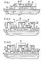
- Electrode 42 has an overlapping portion 42a which overlaps one side of the poly-Si-2 electrode and its protective and shield layers 32, 34, 36 at a position remote from the poly-Si-1 electrode.
- Electrode 43 has an overlapping portion 43a which overlaps one side of the poly-Si-1 electrode 22 and its covering layers 24, 26 28.
- the poly-Si-3 layer is covered by protective oxide and nitride layers 44, 46.
- These layers are etched in a manner previously described to define separate electrodes 42, 43 and provide openings 48, 50 which expose the upper surfaces of CVD SiO2 layers 28, 38, respectively. Thermal oxidation of the poly-Si-3 electrodes after patterning and etching is unnecessary.
- the CVD SiO2 layers 28, 38 are selectively HF etched (10((NH4)2F):HF) to remove the entirety of material of the shield layers 28, 38.
- This step undercuts the overlapping portions 32a, 42a, 43a of the poly-Si-2 and poly-Si-3 electrodes.
- This step provides passageways 52, 54 wherein are exposed the undersurfaces 53, 55 of the overhanging por tions 32a, 42a, 43a of the poly-Si-2 and poly-Si-3 layers.
- a wet chemical etching step which can use any of the available wet chemical silicon etchants, e.g., EDC etch.
- EDC etch wet chemical silicon etchants
- the CVD SiO2 shield layers 28, 38 are originally deposited, they are deposited to a sufficient thickness (8,000 ⁇ -12,000 ⁇ ) to provide passageways 52, 54 of a width that permits circulation of the etchant.
- This step etches away the overlapping portions 32a, 42a, 43a of the poly-Si-2 and poly-Si-3 gate electrodes.
- the overhanging portions can be removed by oxidizing the exposed polysilicon and stripping away the oxide.
- Fig. 4 shows the structure of Fig. 3 following the last described etching step and two additional steps: first, plasma etching to remove the nitride layers 24, 34, 44 and, second, thermal oxidation to grow a thermal oxide layer 60 (2,000 ⁇ ) on the upper surface of the gate electrodes. Next, the device is patterned and implanted to dope the source, drain and gate contacts, annealed and further processed in accordance with conventional procedures to complete the device.
- nitride layers 24, 34, 44 serve to shield the polysilicon gate electrodes during removal of the overlapping portions of the poly-Si-2 and poly-Si-3 electrodes.
- a second embodiment of the process, illustrated in Fig. 5, omits the use of such protective layers. Instead, during the polysilicon deposition steps, the polysilicon layers 122, 132, 142, 143, corresponding to the layers 22, 32, 42 and 43 of Fig. 3, respectively, are grown to a somewhat greater thickness (8,000 ⁇ -12,000 ⁇ ).
- overhanging portions 132a, 142a, 143a are etched not only via passages 52, 54 but on their upper surfaces as well.
- Etching for a period of time sufficient to remove half of the deposited thickness of the polysilicon layers is sufficient to remove the entire overhanging portions while leaving roughly half of the deposited thickness (3,000 ⁇ -4,000 ⁇ ) of the deposited thickness in contact with the substrate surface.
- the amount of polysilicon deposited is thus predetermined so as to provide a final thickness of the conductors sufficient to yield the necessary conductivity characteristics of the gate electrodes.
Landscapes
- Solid State Image Pick-Up Elements (AREA)
Applications Claiming Priority (2)
| Application Number | Priority Date | Filing Date | Title |
|---|---|---|---|
| US866423 | 1986-05-23 | ||
| US06/866,423 US4677737A (en) | 1986-05-23 | 1986-05-23 | Self aligned zero overlap charge coupled device |
Publications (2)
| Publication Number | Publication Date |
|---|---|
| EP0246555A2 true EP0246555A2 (de) | 1987-11-25 |
| EP0246555A3 EP0246555A3 (de) | 1989-05-03 |
Family
ID=25347582
Family Applications (1)
| Application Number | Title | Priority Date | Filing Date |
|---|---|---|---|
| EP87106938A Withdrawn EP0246555A3 (de) | 1986-05-23 | 1987-05-13 | Selbstausgerichtete überlappungslose Gatestruktur eines Ladungsspeicherelementes |
Country Status (3)
| Country | Link |
|---|---|
| US (1) | US4677737A (de) |
| EP (1) | EP0246555A3 (de) |
| JP (1) | JPH0656858B2 (de) |
Cited By (2)
| Publication number | Priority date | Publication date | Assignee | Title |
|---|---|---|---|---|
| EP0570090A1 (de) * | 1992-05-11 | 1993-11-18 | Samsung Electronics Co., Ltd. | Bildsensor und Herstellungsverfahren |
| EP0652589A1 (de) * | 1993-11-10 | 1995-05-10 | Koninklijke Philips Electronics N.V. | Verfahren zur Herstellung einer Halbleitervorrichtung, die zwei koplanare , durch eine dielektrische Schicht getrennte, elektrische Leiter enthält, und durch dieses Verfahren hergestellte Halbleitervorrichtung |
Families Citing this family (4)
| Publication number | Priority date | Publication date | Assignee | Title |
|---|---|---|---|---|
| US6573541B1 (en) | 2000-09-29 | 2003-06-03 | International Business Machines Corporation | Charge coupled device with channel well |
| US6998657B2 (en) * | 2003-10-21 | 2006-02-14 | Micron Technology, Inc. | Single poly CMOS imager |
| JP2007201319A (ja) * | 2006-01-30 | 2007-08-09 | Matsushita Electric Ind Co Ltd | 固体撮像装置およびその製造方法 |
| JP2007201320A (ja) * | 2006-01-30 | 2007-08-09 | Matsushita Electric Ind Co Ltd | 固体撮像装置およびその製造方法 |
Family Cites Families (13)
| Publication number | Priority date | Publication date | Assignee | Title |
|---|---|---|---|---|
| US4077112A (en) * | 1974-09-24 | 1978-03-07 | U.S. Philips Corporation | Method of manufacturing charge transfer device |
| GB1545208A (en) * | 1975-09-27 | 1979-05-02 | Plessey Co Ltd | Electrical solid state devices |
| GB2043336B (en) * | 1979-02-19 | 1983-02-09 | Philips Electronic Associated | Charge-coupled devices |
| JPS55153377A (en) * | 1979-05-18 | 1980-11-29 | Matsushita Electronics Corp | Production of semiconductor device |
| US4402188A (en) * | 1979-07-11 | 1983-09-06 | Skala Stephen F | Nested thermal reservoirs with heat pumping therebetween |
| DE2939456A1 (de) * | 1979-09-28 | 1981-04-16 | Siemens AG, 1000 Berlin und 8000 München | Verfahren zur herstellung von integrierten halbleiterschaltungen, insbesondere ccd-schaltungen, mit selbstjustierten, nichtueberlappenden poly-silizium-elektroden |
| DE2939488A1 (de) * | 1979-09-28 | 1981-04-16 | Siemens AG, 1000 Berlin und 8000 München | Verfahren zur herstellung von integrierten halbleiterschaltungen, insbesondere ccd-schaltungen, mit selbstjustierten, nicht ueberlappenden poly-silizium-elektroden |
| US4319261A (en) * | 1980-05-08 | 1982-03-09 | Westinghouse Electric Corp. | Self-aligned, field aiding double polysilicon CCD electrode structure |
| US4402128A (en) * | 1981-07-20 | 1983-09-06 | Rca Corporation | Method of forming closely spaced lines or contacts in semiconductor devices |
| US4461070A (en) * | 1982-05-28 | 1984-07-24 | General Electric Company | Method for making eutectic charge-coupled devices |
| NL8400224A (nl) * | 1984-01-25 | 1985-08-16 | Philips Nv | Werkwijze ter vervaardiging van een halfgeleiderinrichting en inrichting vervaardigd door toepassing daarvan. |
| US4614564A (en) * | 1984-12-04 | 1986-09-30 | The United States Of America As Represented By The United States Department Of Energy | Process for selectively patterning epitaxial film growth on a semiconductor substrate |
| FR2583573B1 (fr) * | 1985-06-18 | 1988-04-08 | Thomson Csf | Procede de realisation d'un dispositif semi-conducteur a plusieurs niveaux de grille. |
-
1986
- 1986-05-23 US US06/866,423 patent/US4677737A/en not_active Expired - Lifetime
-
1987
- 1987-05-13 EP EP87106938A patent/EP0246555A3/de not_active Withdrawn
- 1987-05-20 JP JP62123622A patent/JPH0656858B2/ja not_active Expired - Lifetime
Cited By (3)
| Publication number | Priority date | Publication date | Assignee | Title |
|---|---|---|---|---|
| EP0570090A1 (de) * | 1992-05-11 | 1993-11-18 | Samsung Electronics Co., Ltd. | Bildsensor und Herstellungsverfahren |
| EP0652589A1 (de) * | 1993-11-10 | 1995-05-10 | Koninklijke Philips Electronics N.V. | Verfahren zur Herstellung einer Halbleitervorrichtung, die zwei koplanare , durch eine dielektrische Schicht getrennte, elektrische Leiter enthält, und durch dieses Verfahren hergestellte Halbleitervorrichtung |
| BE1007768A3 (nl) * | 1993-11-10 | 1995-10-17 | Philips Electronics Nv | Werkwijze ter vervaardiging van een halfgeleiderinrichting en halfgeleiderinrichting vervaardigd met een dergelijke werkwijze. |
Also Published As
| Publication number | Publication date |
|---|---|
| EP0246555A3 (de) | 1989-05-03 |
| JPS62286280A (ja) | 1987-12-12 |
| JPH0656858B2 (ja) | 1994-07-27 |
| US4677737A (en) | 1987-07-07 |
Similar Documents
| Publication | Publication Date | Title |
|---|---|---|
| US5502009A (en) | Method for fabricating gate oxide layers of different thicknesses | |
| US5444021A (en) | Method for making a contact hole of a semiconductor device | |
| US5834816A (en) | MOSFET having tapered gate electrode | |
| KR100273070B1 (ko) | 반도체 소자 및 그 제조방법 | |
| EP0202704B1 (de) | Elektrodenstruktur für Halbleiteranordnung und Verfahren zu ihrer Herstellung | |
| JPS5836508B2 (ja) | 半導体装置の製造方法 | |
| EP0246555A2 (de) | Selbstausgerichtete überlappungslose Gatestruktur eines Ladungsspeicherelementes | |
| US6114217A (en) | Method for forming isolation trenches on a semiconductor substrate | |
| US5620911A (en) | Method for fabricating a metal field effect transistor having a recessed gate | |
| KR0183718B1 (ko) | 도전층을 포함하는 소자분리구조를 갖는 반도체장치의 제조방법 | |
| KR100214534B1 (ko) | 반도체소자의 소자격리구조 형성방법 | |
| JP2971085B2 (ja) | 半導体装置の製造方法 | |
| KR100313543B1 (ko) | 플랫 롬 제조방법 | |
| KR100245075B1 (ko) | 반도체소자의 소자격리 산화막 형성방법 | |
| KR0123782B1 (ko) | Eprom반도체 장치 및 이의 형성방법 | |
| JPS58171864A (ja) | 半導体装置 | |
| KR19990056756A (ko) | 아날로그 반도체 소자의 제조 방법 | |
| KR0172268B1 (ko) | 반도체 소자의 제조방법 | |
| KR100338095B1 (ko) | 반도체소자의콘택홀형성방법 | |
| KR100478495B1 (ko) | 반도체 장치 및 그의 제조 방법 | |
| KR0166504B1 (ko) | 반도체 소자의 미세 콘택홀 형성방법 | |
| KR950007422B1 (ko) | 반도체 장치의 소자격리 방법 | |
| KR100261993B1 (ko) | 메탈라인을 이용한 캐패시터 제조방법 | |
| KR100257081B1 (ko) | 다결정 실리콘 산화공정을 이용한 반도체 소자 배선 제조방법 | |
| KR19980025087A (ko) | 전하전송장치의 제조방법 |
Legal Events
| Date | Code | Title | Description |
|---|---|---|---|
| PUAI | Public reference made under article 153(3) epc to a published international application that has entered the european phase |
Free format text: ORIGINAL CODE: 0009012 |
|
| AK | Designated contracting states |
Kind code of ref document: A2 Designated state(s): DE FR GB NL |
|
| PUAL | Search report despatched |
Free format text: ORIGINAL CODE: 0009013 |
|
| AK | Designated contracting states |
Kind code of ref document: A3 Designated state(s): DE FR GB NL |
|
| 17P | Request for examination filed |
Effective date: 19891031 |
|
| 17Q | First examination report despatched |
Effective date: 19910613 |
|
| STAA | Information on the status of an ep patent application or granted ep patent |
Free format text: STATUS: THE APPLICATION IS DEEMED TO BE WITHDRAWN |
|
| 18D | Application deemed to be withdrawn |
Effective date: 19911024 |
|
| RIN1 | Information on inventor provided before grant (corrected) |
Inventor name: BENN, PAULINE Inventor name: CORRIE, BRIAN L. Inventor name: MCELEVEY, MICHAEL J. |