EP0247883B1 - Digitales Fernsteuerungsübertragungsgerät - Google Patents
Digitales Fernsteuerungsübertragungsgerät Download PDFInfo
- Publication number
- EP0247883B1 EP0247883B1 EP87304747A EP87304747A EP0247883B1 EP 0247883 B1 EP0247883 B1 EP 0247883B1 EP 87304747 A EP87304747 A EP 87304747A EP 87304747 A EP87304747 A EP 87304747A EP 0247883 B1 EP0247883 B1 EP 0247883B1
- Authority
- EP
- European Patent Office
- Prior art keywords
- pulses
- period
- pulse
- code
- information signal
- Prior art date
- Legal status (The legal status is an assumption and is not a legal conclusion. Google has not performed a legal analysis and makes no representation as to the accuracy of the status listed.)
- Expired - Lifetime
Links
Images


Classifications
-
- G—PHYSICS
- G08—SIGNALLING
- G08C—TRANSMISSION SYSTEMS FOR MEASURED VALUES, CONTROL OR SIMILAR SIGNALS
- G08C19/00—Electric signal transmission systems
- G08C19/16—Electric signal transmission systems in which transmission is by pulses
- G08C19/28—Electric signal transmission systems in which transmission is by pulses using pulse code
Definitions
- the present invention relates to a digital remote control apparatus, and more particularly to an improvement in the transmission format of such an apparatus.
- Such a kind of digital remote control apparatus is used as a remote control apparatus for conducting channel setting, volume adjustment, ON/OFF of the power supply, tape play, tape stop, fast forwarding, rewinding, setting (an advanced programming) of start/stop time, date, channel, and days of the week of video or audio recording in such as a television, a video tape recorder, and an audio tape recorder. It is also used in the selection of cooling, heating, or dehumidification, the setting of temperature and time, ON/OFF of the power supply such as in an air conditioner. In summary, it is used as a remote control apparatus in such as electric appliances, automobiles, robots, and electro medical equipments.
- Figures 1 and 2 show block constructions of a general digital remote control system.
- the reference numeral 31 designates a transmitting circuit including a key input read circuit 11, a code modulation circuit 12, a timing generator 13, and an oscillator 14.
- the reference numeral 32 designates a receiving circuit including a preamplifier 18, and a remote control signal demodulation circuit 19.
- the reference numeral 33 designates a light emitting diode or other light emitting element.
- the reference numeral 34 designates a photo diode or other light receiving element.
- the reference numeral 10 designates a key matrix for inputting information to the key input read circuit 11 of the transmitting circuit 31.
- the reference numeral 15 designates a driver circuit comprising a transistor which receives the information from the code modulation circuit 12 of the transmitting circuit 31 and makes a current in accordance with the information flow through the light emitting element 33.
- the reference numeral 16 designates a light information transmitted from the light emitting element 33 to the light receiving element 34.
- the information to be sent out is input to the transmitting circuit 31 by the key matrix 10, and this is encoded by the transmitting circuit 31, and this is modulated and transmitted in a light signal 16 by the light emitting diode 33.
- the transmitted light signal 16 is received by the photo diode 34, and this is demodulated by the receiving circuit 32 to decode the instruction.
- Figure 3 shows a transmission format in such a kind of transmission system which is already developed by the inventor.
- the distinction of one bit information "0" and “1” are conducted by the intervals 41 and 42 between the two subsequent pulses as shown in Figure 3. That is, the short time interval 41 from the rising up of the pulse to the rising up of the next pulse (in Figure 3(a)) corresponds to a bit "0", and the long time interval 42 of that ( Figure 3(b)) corresponds to a bit "1".
- These information "0” and "1” of several bits are combined to constitute a word as shown in Figure 4, and the kinds of instructions are distinguished from each other on the basis of the data code of this word.
- one word 5 comprises a six bit construction, and in this figure the data bit of the word 5 is "010000".
- the code 6 designates the repetition period of the word 5.
- EP-A-0162327 discloses a pulse coding arrangement which defines "0" and "1" as discussed above with reference to Figs. 3 and 4.
- the transmission code is made up of a custom code and an instruction code, separated by a pulse interval four times the length of the pulse interval signifying "0".
- US-A-3767855 discloses a code arrangement in which synchronizing pulses mark the boundaries between successive time intervals, and each time interval contains an information pulse representing a value depending on the timing of the information pulse in the time interval. Eight possible information pulse timings are defined, so that the timing of the information pulse in a time interval can represent any one of "0" to "7".
- EP-A-0234948 discloses a coding system in which a word contains a plurality of data intervals between successive synchronous pulses at a set frequency, and the timing of a data pulse in a data interval defines data value of the interval as "0" or "1".
- the present invention provides apparatus for encoding and transmitting input data as set out in claim 1, a method of signalling as set out in claim 13 and a pulsed information signal as set out in claim 14.
- the remaining claims set out optional features.
- An embodiment of the present invention provides an improved digital remote control transmission apparatus having a constant word length and having superiority in anti-noise characteristics, and further capable of use with a plurality of independent remote control systems.
- Figure 6 shows a construction of the transmission code of a digital remote control transmission apparatus as an embodiment of the present invention.
- the reference numeral 21 designates a synchronization pulse of a predetermined period, and this synchronization pulse is made from the pulse which is output from the timing generator 13 by that pulse being applied to the code modulation circuit 12, which generator 13 receives pulses of a predetermined period from the oscillator 14 shown in Figure 2.
- the reference numeral 22 designates a data pulse inserted between the synchronization pulses 21. For example, this data pulse is produced by that desired information from the key matrix 10 is read in into the key input read circuit 11, and synchronized with the timings of the timing pulses output from the timing generator 13 thereat, and that the synchronized data is input to the code modulation circuit 12.
- the reference numeral 1 designates a one bit period corresponding to the period between the synchronization pulses 21.
- the reference numeral 2 designates a custom code for distinguishing the apparatus to be controlled (at the receiving side). In this embodiment this custom code is constituted in a four bit construction.
- the reference numeral 3 designates a data code for operating the apparatus to be controlled (instruction code). In this embodiment this data code is constituted in a six bit construction.
- the reference numeral 4 designates a separation code (separation period) for separating the custom code 2 and the data code 3, which is provided as a characteristics of the present invention. In this embodiment this separation code comprises a code in which data pulses are not inserted between the two synchronization pulses 21.
- the reference numeral 5 designates a one word of the transmission code, and the reference numeral 6 designates a repetition period.
- the construction of the remote control system of the present embodiment is the same as those of Figures 1 and 2.
- the distinction of the bit "0" and “1" are made as follows. That is, when the period 23 or 25 from the rising up of the synchronization pulse to the rising up of the data pulse subsequent to the synchronization pulse (or from the falling down of the synchronization pulse to the falling down of the data pulse subsequent thereto) is 1 ms the bit is "0" ( Figure 7(a)), and when the former period is 2 ms the bit is "1" ( Figure 7(b)). Accordingly, the period 1 of the synchronization pulse 21 is 3 ms.
- the four bit custom code 2 (which is "1001" in the example of Figure 6) is transmitted, and next the period including no data pulses (separation code) 4 is transmitted, and furthermore the six bit data code 3 (which is "110011" in the example of Figure 6) is transmitted.
- the one word length of the transmission code 5 which has the same bit number is constant regardless of the number of the "0" (or "1") in the data.
- the data interpretation is easened.
- a noise 71 as shown in Figure 8 is inserted into the data of bit information "0" it becomes as such that two data pulses are inserted in a bit, and it is possible to prevent the malfunction of the receiving side because it is possible to judge them as noises easily at the receiving side.
- the transmission code 5 is separated into the custom code 2 and the data code (instruction code) 3, and the period (separation code) 4 representing the boundary therebetween is provided. Accordingly, even if the numbers of bits of the whole of the transmission code are equal to each other, it is possible to produce code systems which do not interfere with each other by changing the number of bits in the custom code and the data code. That is, it is possible to produce a plurality of independent remote control systems with the use of the transmission code having the same number of bits.
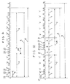
- Figure 9 shows a construction of the transmission code of the second embodiment of the present invention.
- This second embodiment is different from the first embodiment only in the separation code 4A.
- This separation code 4A is constructed in such a manner that two data pulses 22 are inserted between two synchronization pulses 21.
- the four bit custom code 2 (which is "1001" in the example of figure 9) is transmitted as similarly as the first embodiment, and next a separation code 4A including two data pulses is transmitted, and the six bit data code 3 (which is "110011" in the example of Figure 9) is transmitted.
- the transmission code 5 is separated into the custom code 2 and the data code 3 by providing the separation code 4A as a boundary, it is possible to produce code systems which do not interfere with each other even if the numbers of bits of the whole of the transmission code are equal to each other by changing the number of bits in the custom code and the data code. That is, it is possible to produce a plurality of code systems with the use of the transmission codes having the same number of bits.
- FIG 10 shows a construction of a transmission code as a third embodiment of the present invention.
- This third embodiment is different from the first embodiment only in the separation code 4B.
- This separation code 4B is constituted by the two periods A in which data pulses are not inserted between the two synchronization pulses 21 and the period B in which two data pulses 22 are inserted between two synchronization pulses 21, which period B is inserted between the two periods A.
- four bit custom code 2 (which is "1001" in the example of Figure 10) is at first transmitted as similarly as the first embodiment, and subsequent thereto a separation code 4B for separating the custom code and the instruction code is transmitted, and furthermore five bit instruction code 3 (which is "01001" in the example of Figure 10) is transmitted.
- one word length of the transmission code 5 having the same bit number is constant regardless of the number of the data "0" (or "1").
- the transmission code 5 is separated into the custom code 2 and the instruction code 3 and a separation code 4B representing the boundary therebetween is provided, even if the numbers of bits of the whole of the transmission code are equal to each other, it is possible to produce code systems which do not interfere with each other by changing the number of bits in the custom code 2 and the instruction code 3. That is, it is possible to produce a plurality of code systems with the use of the transmission code having the same number of bits.
- the separation code 4B representing the boundary between the custom code 2 and the instruction code 3 is constituted by the period A and the period B having two data pulses between the two synchronization pulses, it is possible to produce code systems which, having different combinations of the periods A and B, do not interfere with each other.
- the separation code 4B comprises two periods of A and a period of B in sequence of "ABA", but in this third embodiment it is possible to produce 6 kinds of code systems by only using the separation code 4B in a case where the separation code 4B is a 3 bit code comprising two kinds of periods. It is possible to increase the number of the periods constituting the period 4B in order to produce a larger number of code systems which do not interfere with each other.
- the period of the synchronization pulse is 3 ms
- the time length between the rising ups of the synchronization pulse and the data pulse which corresponds to the bit "0" is 1 ms
- that which corresponds to the bit "1” is 2 ms
- these tine lengths can be set to any values on a condition that the time lengths may be distinguished from each other as those representing the bit "0" and "1", respectively.
- the synchronization pulse and the data pulse may be frequency modulated by a particular frequency e.g. 38 KHz so as to conduct a transmission in a narrow frequency band, whereby the anti-noise characteristics of the transmission system is enhanced.
- a leading pulse having a long pulse width may be inserted before the transmission code so that the arrival of the transmission signal may be easily detected at the receiving side.
- the pulse widths of the synchronization pulse 21 and the data pulse 22 may be different from each other so as to facilitate the distinction between the two pulses at the receiving side.
- the number of bits of the custom code and the data code may be different from each other so as to facilitate the distinction between the two codes at the receiving side.
- custom code 2 is transmitted before and the instruction code 3 is transmitted after, but the instruction code 3 can be transmitted before.
- the period 4 for separating the custom code 2 and the data code 3 comprises only one period of the synchronization pulse, but this may comprise an arbitrary number of periods.
- the separation code 4B for separating the custom code 2 and the instruction code 3 is made of only 3 periods of the synchronization pulses, but any number of periods can be used arbitrarily as already described.
- the period B which constitutes the separation code 4B in combination with the period A has two data pulses between the two synchronization pulses, but the number of the data pulses of the period B can be selected arbitrarily.
- the transmission code is constituted by a custom code, an instruction code, and a separation code in such a manner that the respective bit information of "0" or "1" of the custom code and the instruction code is represented by the position of the data pulse inserted between the synchronization pulses of a predetermined period, whereby the data interpretation is easened and anti-noise characteristics is enhanced. Furthermore, interference between remote control systems is reduced, and it is made possible to construct a plurality of independent remote control systems.
Landscapes
- Physics & Mathematics (AREA)
- General Physics & Mathematics (AREA)
- Selective Calling Equipment (AREA)
Claims (14)
- Gerät zur Codierung und Übertragung eingegebener Daten, mit Eingabemitteln (10,11) zum Empfang eingegebener Daten und mit Codier- und Sendemittel (12, 15, 33) zur Codierung der eingegebenen Daten und zur Sendung dieser als ein gepulstes Informationssignal (5) mit einer Vielzahl erster Impulse (21), die zu einer vorbestimmten Folgefrequenz auftreten, um dadurch eine Vielzahl von Perioden (1) einer vorbestimmten Dauer festzulegen, wobei jede betreffende Periode (1) mit einem betreffenden der ersten Impulse (21) beginnt und am nächstfolgenden der ersten Impulse (21) endet,wobei die Codier- und Sendemittel erste und zweite Abschnitte (2, 3) des gepulsten Informationssignals (5) und einen Trennabschnitt (4; 4A; 4B) bilden, der den ersten vom zweiten Abschnitt (2, 3) trennt, wobei die Codier- und Sendemittel die Abschnitte derart bilden, daß im ersten Abschnitt (2) und im zweiten Abschnitt (3) ein betreffender zweiter Impuls (22) in jeder Periode (1) der vorbestimmten Dauer auftritt, und wobei der Datenwert, der von dem gepulsten Informationssignal in jeder Periode (1) des ersten Abschnitts (2) und in jeder Periode (1) des zweiten Abschnitts (3) durch die Stellung des betreffenden zweiten Impulses (22) in der Periode (1) dargestellt wird,dadurch gekennzeichnet, daßder Trennabschnitt (4; 4A; 4B) wenigstens eine besagte Periode (1) der vorbestimmten Dauer umfaßt, die an einem betreffenden der ersten Impulse (21) beginnt und am nächstfolgenden der ersten Impulse (21) endet, in denen keine der zweiten Impulse (22) oder in denen eine Vielzahl der zweiten Impulse (22) auftreten.
- Gerät nach Anspruch 1, dessen Trennabschnitt (4; 4B) die Periode (1) der vorbestimmten Dauer umfaßt, die an einem betreffenden der ersten Impulse (21) beginnt und am nächstfolgenden der zweiten Impulse (21) endet, in denen keine der zweiten Impulse auftreten.
- Gerät nach Anspruch 1 oder 2, dessen Trennabschnitt (4; 4B) die Periode (1) der vorbestimmten Dauer umfaßt, die an einem betreffenden der ersten Impulse (21) beginnt und am nächstfolgenden der zweiten Impulse (21) endet, in denen eine Vielzahl der zweiten Impulse auftreten.
- Gerät nach Anspruch 3, bei dem in jeder besagten Periode (1) des ersten Abschnitts (2) oder des zweiten Abschnitts (3) das gepulste Informationssignal einen ersten Datenwert trägt, wenn der betreffende zweite Impuls (22) an einer ersten Stelle in der Periode ist, und das gepulste Informationssignal einen zweiten Datenwert trägt, wenn der betreffende zweite Impuls (22) an einer zweiten Stelle in der Periode ist, und wobei der Trennabschnitt eine besagte Periode (1) der vorbestimmten Dauer enthält, der an einem betreffenden der ersten Impulse (21) beginnt und am nächstfolgenden der ersten Impulse (21) endet, in denen ein zweiter Impuls an der ersten Stelle und ein zweiter Impuls an der zweiten Stelle auftritt.
- Gerät nach einem der vorstehenden Ansprüche, bei dem die ersten und die zweiten Impulse voneinander verschiedene Breiten haben.
- Gerät nach einem der vorstehenden Ansprüche, bei dem die ersten und die zweiten Impulse auf eine Trägerfrequenz moduliert sind.
- Gerät nach einem der vorstehenden Ansprüche, bei dem die ersten und zweiten Abschnitte (2, 3) des Signals eine unterschiedliche Anzahl von Bit umfaßt.
- Gerät nach einem der vorstehenden Ansprüche, das ein Fernsteuergerät enthält und dessen gepulstes Informationssignal ein Steuersignal für ein Empfangsgerät ist.
- Gerät nach Anspruch 8, bei dem einer der ersten und zweiten Abschnitte kennzeichnet, für welches Empfangsgerät ein Signal bestimmt ist, und bei dem der andere der ersten und zweiten Abschnitte einen Fernsteuerbefehl enthält.
- Gerät nach Anspruch 8 oder 9, bei dem der Trennabschnitt (4B) wenigstens eine besagte Periode (1) der vorbestimmten Dauer enthält, die an einem betreffenden der ersten Impulse (21) beginnt und am nächstfolgenden der ersten Impulse (21) endet, in denen keine zweiten Impulse auftreten, und wenigstens eine besagte Periode (1) der bestimmten Dauer, die an einem betreffenden der ersten Impulse (21) beginnt und am nächstfolgenden der ersten Impulse (21) endet, in denen eine Vielzahl zweiter Impulse auftreten, wobei das Muster der Periodenarten in dem Trennabschnitt ein Fernsteuersystem kennzeichnet, das zu dem das Gerät gehört.
- Empfänger zum Empfang und zur Decodierung eines gepulsten Signals nach einem der Ansprüche 1 bis 10.
- Fernsteuersystem mit einem Sender, nach einem der Ansprüche 1 bis 10 und einem Empfänger nach Anspruch 11.
- Zeichengabeverfahren unter Verwendung eines gepulsten Informationssignals (5) mit einer Vielzahl erster Impulse (21), die mit einer vorbestimmten Wiederholfreqenz auftreten, um dadurch eine Vielzahl von Perioden (1) einer bestimmten Dauer festzulegen, wobei jede betreffende Periode (1) an einem betreffenden der ersten Impulse (21) beginnt und am nächstfolgenden der ersten Impulse (21) endet,wobei das gepulste Informationssignal (5) erste und zweite Abschnitte (2, 3) derart enthält, daß in dem ersten Abschnitt (2) und in dem zweiten Abschnitt (3) ein betreffender zweiter Impuls (22) in jeder Periode (1) der vorbestimmten Dauer auftritt, und wobei der Datenwert, den das gepulste Informationssignal trägt, in jeder Periode (1) des ersten Abschnitts und in jeder Periode (1) des zweiten Abschnitts (3) durch die Stelle des betreffenden zweiten Impulses (22) in jeder Periode (1) dargestellt wird, und wobei das gepulste Informationssignal (5) auch einen Trennabschnitt (4; 4A, 4B) enthält, der den ersten vom zweiten Abschnitt (2, 3) trennt,dadurch gekennzeichnet, daßder Trennabschnitt (4; 4A; 4B) wenigstens eine besagte Periode (1) der vorbestimmten Dauer umfaßt, die an einem betreffenden der ersten Impulse (21) beginnt und am nächstfolgenden der ersten Impulse (21) endet, in denen keine der zweiten Impulse (22) oder in denen eine Vielzahl der zweiten Impulse (22) auftreten.
- Gepulstes Informationssignal (5) mit einer Vielzahl erster Impulse (21), die mit einer vorbestimmten Folgefrequenz auftreten, um dadurch eine Vielzahl von Perioden (1) einer vorbestimmten Dauer festzulegen, wobei jede betreffende Periode (1) an einem betreffenden der ersten Impulse (21) beginnt und beim nächstfolgenden der ersten Impulse (21) endet,wobei das gepulste Informationssignal (5) erste und zweite Abschnitte (2, 3) derart enthält, daß in dem ersten Abschnitt (2) und in dem zweiten Abschnitt (3) ein betreffender zweiter Impuls (22) in jeder Periode (1) der vorbestimmten Dauer auftritt, und wobei der Datenwert, den das gepulste Informationssignal trägt, in jeder Periode (1) des ersten Abschnitts und in jeder Periode (1) des zweiten Abschnitts (3) durch die Stelle des betreffenden zweiten Impulses (22) in jeder Periode (1) dargestellt wird, und wobei das gepulste Informationssignal (5) auch einen Trennabschnitt (4; 4A, 4B) enthält, der den ersten vom zweiten Abschnitt (2, 3) trennt,dadurch gekennzeichnet, daßder Trennabschnitt (4; 4A; 4B) wenigstens eine besagte Periode (1) der vorbestimmten Dauer enthält, die an einem betreffenden der ersten Impulse (21) beginnt und am nächstfolgenden der ersten Impulse (21) endet, in denen keine zweiten Impulse (22) oder in denen eine Vielzahl der zweiten Impulse (22) auftreten.
Applications Claiming Priority (6)
| Application Number | Priority Date | Filing Date | Title |
|---|---|---|---|
| JP61125997A JPH0632521B2 (ja) | 1986-05-30 | 1986-05-30 | デイジタルリモ−トコントロ−ル伝送装置 |
| JP125997/86 | 1986-05-30 | ||
| JP159197/86 | 1986-07-07 | ||
| JP15919786A JPH0773389B2 (ja) | 1986-07-07 | 1986-07-07 | デイジタルリモ−トコントロ−ル伝送装置 |
| JP167687/86 | 1986-07-15 | ||
| JP16768786A JP2511887B2 (ja) | 1986-07-15 | 1986-07-15 | デイジタルリモ−トコントロ−ル伝送装置 |
Publications (3)
| Publication Number | Publication Date |
|---|---|
| EP0247883A2 EP0247883A2 (de) | 1987-12-02 |
| EP0247883A3 EP0247883A3 (en) | 1989-06-14 |
| EP0247883B1 true EP0247883B1 (de) | 1996-04-10 |
Family
ID=27315241
Family Applications (1)
| Application Number | Title | Priority Date | Filing Date |
|---|---|---|---|
| EP87304747A Expired - Lifetime EP0247883B1 (de) | 1986-05-30 | 1987-05-28 | Digitales Fernsteuerungsübertragungsgerät |
Country Status (4)
| Country | Link |
|---|---|
| US (1) | US4914428A (de) |
| EP (1) | EP0247883B1 (de) |
| CN (1) | CN1008138B (de) |
| DE (1) | DE3751768T2 (de) |
Families Citing this family (21)
| Publication number | Priority date | Publication date | Assignee | Title |
|---|---|---|---|---|
| US5045947A (en) * | 1989-05-31 | 1991-09-03 | Jack Beery | Television receiver having memory control for tune-by-label feature |
| KR930006424B1 (ko) * | 1990-10-27 | 1993-07-14 | 삼성전자 주식회사 | 재편성원격제어송신기의 펄스잡음검출 및 정정방법 |
| US5193210A (en) * | 1991-07-29 | 1993-03-09 | Abc Auto Alarms, Inc. | Low power RF receiver |
| DE4128974A1 (de) * | 1991-08-31 | 1993-03-04 | Telefunken Electronic Gmbh | Betrieb eines systems mittels einer fernbedienung |
| US6299065B1 (en) | 1992-01-13 | 2001-10-09 | Metrologic Instruments, Inc. | Bar code processing system with multiport signal decoder |
| USD348741S (en) | 1992-06-25 | 1994-07-12 | Don Ellison | Light for a remote control unit |
| USD354730S (en) | 1993-04-26 | 1995-01-24 | Herbert Collins | Remotely operated light bulb output controller |
| US5594429A (en) * | 1993-10-27 | 1997-01-14 | Alps Electric Co., Ltd. | Transmission and reception system and signal generation method for same |
| US5523800A (en) * | 1993-11-04 | 1996-06-04 | Dudek; Walter J. | Programmable alpha/numeric channel entry translation function for hand held video remote controls |
| USD375373S (en) | 1995-09-27 | 1996-11-05 | Mele Peter C | Light for a remote control device |
| JP2943712B2 (ja) * | 1996-08-23 | 1999-08-30 | 日本電気株式会社 | 遠隔制御方式 |
| KR100218009B1 (ko) * | 1997-05-27 | 1999-09-01 | 윤종용 | 채터링(Chattering)노이즈에 의한 키 오동작 방지 장치 및 방법 |
| US6747590B1 (en) * | 2001-02-12 | 2004-06-08 | Harold J. Weber | Alternate command signal decoding option for a remotely controlled apparatus |
| RU2244344C2 (ru) * | 2002-10-16 | 2005-01-10 | Московский государственный институт электронной техники (технический университет) | Устройство формирования команд управления двухпозиционными объектами |
| RU2237287C2 (ru) * | 2002-10-16 | 2004-09-27 | Московский государственный институт электронной техники (технический университет) | Устройство приема команд управления |
| RU2274904C2 (ru) * | 2004-02-09 | 2006-04-20 | ООО ВТД "Гранит-микро" | Устройство управления моторными приводами разъединителей контактной сети |
| US7592895B2 (en) * | 2005-10-17 | 2009-09-22 | Lear Corporation | System and method for remotely controlling a function |
| US20070274305A1 (en) * | 2006-05-26 | 2007-11-29 | Delta Systems, Inc. | System and method for remotely controlling device |
| CN101699533B (zh) * | 2009-05-08 | 2012-02-29 | 四川和芯微电子股份有限公司 | 一种应用于无线遥控器的编码、解码方法 |
| CN102110353B (zh) * | 2009-12-28 | 2013-05-08 | 比亚迪股份有限公司 | 一种遥控射频信号发射控制方法、装置及汽车遥控系统 |
| RU2595494C2 (ru) * | 2014-04-02 | 2016-08-27 | Федеральное государственное казенное учреждение "Войсковая часть 35533" | Способ образования импульсных кодовых последовательностей и их обработки для систем передачи дискретной информации |
Family Cites Families (18)
| Publication number | Priority date | Publication date | Assignee | Title |
|---|---|---|---|---|
| US3257651A (en) * | 1962-04-18 | 1966-06-21 | Lyle D Feisel | Pulse position modulation information handling system |
| US3631398A (en) * | 1970-10-12 | 1971-12-28 | Whirlpool Co | Tv remote control system |
| JPS5113527B1 (de) * | 1971-02-25 | 1976-04-30 | ||
| US3793636A (en) * | 1972-01-28 | 1974-02-19 | Moog Inc | Nonconductive data link control apparatus |
| US4099163A (en) * | 1976-03-29 | 1978-07-04 | The Magnavox Company | Method and apparatus for digital data transmission in television receiver remote control systems |
| US4213119A (en) * | 1976-04-29 | 1980-07-15 | Energy Optics, Inc. | Remote meter reading system providing demand readings and load control from conventional KWH meters |
| DE2737467C2 (de) * | 1977-08-19 | 1982-05-06 | Deutsche Itt Industries Gmbh, 7800 Freiburg | Fernsteueranordnung |
| US4143368A (en) * | 1977-12-05 | 1979-03-06 | General Motors Corporation | Vehicle operator security system |
| US4245347A (en) * | 1978-01-18 | 1981-01-13 | Hutton Thomas J | Remote equipment control system with low duty cycle communications link |
| JPS6046585B2 (ja) * | 1979-03-06 | 1985-10-16 | 株式会社リコー | シリアル・デ−タ伝送方式 |
| JPS56119596A (en) * | 1980-02-26 | 1981-09-19 | Nec Corp | Control signal generator |
| US4418333A (en) * | 1981-06-08 | 1983-11-29 | Pittway Corporation | Appliance control system |
| US4482947A (en) * | 1982-04-12 | 1984-11-13 | Zenith Electronics Corporation | Multi-function, multi-unit remote control system and method therefor |
| US4514732A (en) * | 1982-08-23 | 1985-04-30 | General Electric Company | Technique for increasing battery life in remote control transmitters |
| DE3338046A1 (de) * | 1983-04-07 | 1984-10-18 | Jürgen Prof. Dipl.-Ing. Wagner | Drahtlose fernsteuerung zum einstellen des zustandes mehrerer elektrischer verbraucher |
| JPS60227547A (ja) * | 1984-04-25 | 1985-11-12 | Mitsubishi Electric Corp | デイジタルリモ−トコントロ−ル装置 |
| US4623887A (en) * | 1984-05-15 | 1986-11-18 | General Electric Company | Reconfigurable remote control |
| JPS62202300A (ja) * | 1986-02-28 | 1987-09-05 | 三菱電機株式会社 | デイジタルリモ−トコントロ−ル装置 |
-
1987
- 1987-05-28 EP EP87304747A patent/EP0247883B1/de not_active Expired - Lifetime
- 1987-05-28 US US07/055,129 patent/US4914428A/en not_active Expired - Fee Related
- 1987-05-28 DE DE3751768T patent/DE3751768T2/de not_active Expired - Fee Related
- 1987-05-29 CN CN87103886.2A patent/CN1008138B/zh not_active Expired
Also Published As
| Publication number | Publication date |
|---|---|
| CN87103886A (zh) | 1988-01-20 |
| EP0247883A3 (en) | 1989-06-14 |
| DE3751768T2 (de) | 1996-08-22 |
| DE3751768D1 (de) | 1996-05-15 |
| US4914428A (en) | 1990-04-03 |
| EP0247883A2 (de) | 1987-12-02 |
| CN1008138B (zh) | 1990-05-23 |
Similar Documents
| Publication | Publication Date | Title |
|---|---|---|
| EP0247883B1 (de) | Digitales Fernsteuerungsübertragungsgerät | |
| US4833467A (en) | Data transmission system | |
| EP0162327B2 (de) | Digitales Fernsteuerverfahren | |
| JP2697734B2 (ja) | 遠隔操作装置 | |
| US4814741A (en) | Digital remote control device | |
| EP0186468B1 (de) | Übertragungssystem für Videoinformationsgerät | |
| EP0159362B1 (de) | Datenübertragungssystem | |
| US5977865A (en) | Bit encoding in home control systems | |
| GB2187366A (en) | Synchronizing signal decoding | |
| EP0112697A2 (de) | Vorrangkodierungssystem | |
| EP0223311B1 (de) | Fernsteuersystem | |
| KR960003881B1 (ko) | 가정용 비디오 장치의 예약프로그래밍 방법 | |
| JP3197415B2 (ja) | コマンド通信方式 | |
| US5406402A (en) | Faulty operation prevention circuit for infrared-ray remote controller | |
| JP2511887B2 (ja) | デイジタルリモ−トコントロ−ル伝送装置 | |
| JPS6314599A (ja) | デイジタルリモ−トコントロ−ル伝送装置 | |
| JPH0632521B2 (ja) | デイジタルリモ−トコントロ−ル伝送装置 | |
| JPH0560705B2 (de) | ||
| SU563729A1 (ru) | Система передачи данных черех атс с информационной обратной св зью | |
| JPS6342597A (ja) | デイジタルリモ−トコントロ−ル装置 | |
| JP3779022B2 (ja) | 機器の切換装置 | |
| JPH0541895A (ja) | 遠隔制御装置 | |
| JPH0740384B2 (ja) | タイマ予約設定装置 | |
| JPS62161298A (ja) | デイジタルリモ−トコントロ−ル装置 | |
| JPH0511709B2 (de) |
Legal Events
| Date | Code | Title | Description |
|---|---|---|---|
| PUAI | Public reference made under article 153(3) epc to a published international application that has entered the european phase |
Free format text: ORIGINAL CODE: 0009012 |
|
| AK | Designated contracting states |
Kind code of ref document: A2 Designated state(s): DE FR GB |
|
| PUAL | Search report despatched |
Free format text: ORIGINAL CODE: 0009013 |
|
| AK | Designated contracting states |
Kind code of ref document: A3 Designated state(s): DE FR GB |
|
| 17P | Request for examination filed |
Effective date: 19890829 |
|
| 17Q | First examination report despatched |
Effective date: 19920410 |
|
| GRAH | Despatch of communication of intention to grant a patent |
Free format text: ORIGINAL CODE: EPIDOS IGRA |
|
| GRAA | (expected) grant |
Free format text: ORIGINAL CODE: 0009210 |
|
| AK | Designated contracting states |
Kind code of ref document: B1 Designated state(s): DE FR GB |
|
| REF | Corresponds to: |
Ref document number: 3751768 Country of ref document: DE Date of ref document: 19960515 |
|
| ET | Fr: translation filed | ||
| PLBE | No opposition filed within time limit |
Free format text: ORIGINAL CODE: 0009261 |
|
| STAA | Information on the status of an ep patent application or granted ep patent |
Free format text: STATUS: NO OPPOSITION FILED WITHIN TIME LIMIT |
|
| 26N | No opposition filed | ||
| REG | Reference to a national code |
Ref country code: GB Ref legal event code: IF02 |
|
| PGFP | Annual fee paid to national office [announced via postgrant information from national office to epo] |
Ref country code: GB Payment date: 20040526 Year of fee payment: 18 |
|
| PGFP | Annual fee paid to national office [announced via postgrant information from national office to epo] |
Ref country code: FR Payment date: 20050511 Year of fee payment: 19 |
|
| PGFP | Annual fee paid to national office [announced via postgrant information from national office to epo] |
Ref country code: DE Payment date: 20050526 Year of fee payment: 19 |
|
| PG25 | Lapsed in a contracting state [announced via postgrant information from national office to epo] |
Ref country code: GB Free format text: LAPSE BECAUSE OF NON-PAYMENT OF DUE FEES Effective date: 20050528 |
|
| GBPC | Gb: european patent ceased through non-payment of renewal fee |
Effective date: 20050528 |
|
| PG25 | Lapsed in a contracting state [announced via postgrant information from national office to epo] |
Ref country code: DE Free format text: LAPSE BECAUSE OF NON-PAYMENT OF DUE FEES Effective date: 20061201 |
|
| REG | Reference to a national code |
Ref country code: FR Ref legal event code: ST Effective date: 20070131 |
|
| PG25 | Lapsed in a contracting state [announced via postgrant information from national office to epo] |
Ref country code: FR Free format text: LAPSE BECAUSE OF NON-PAYMENT OF DUE FEES Effective date: 20060531 |