EP0249285A1 - Verfahren und Vorrichtung zum Füllen von Bildoberflächenteilen mit einem Oberflächenmuster - Google Patents
Verfahren und Vorrichtung zum Füllen von Bildoberflächenteilen mit einem Oberflächenmuster Download PDFInfo
- Publication number
- EP0249285A1 EP0249285A1 EP87201056A EP87201056A EP0249285A1 EP 0249285 A1 EP0249285 A1 EP 0249285A1 EP 87201056 A EP87201056 A EP 87201056A EP 87201056 A EP87201056 A EP 87201056A EP 0249285 A1 EP0249285 A1 EP 0249285A1
- Authority
- EP
- European Patent Office
- Prior art keywords
- pattern
- image
- memory
- word
- raster
- Prior art date
- Legal status (The legal status is an assumption and is not a legal conclusion. Google has not performed a legal analysis and makes no representation as to the accuracy of the status listed.)
- Ceased
Links
Images


Classifications
-
- G—PHYSICS
- G06—COMPUTING OR CALCULATING; COUNTING
- G06T—IMAGE DATA PROCESSING OR GENERATION, IN GENERAL
- G06T11/00—Two-dimensional [2D] image generation
- G06T11/40—Filling planar surfaces by adding surface attributes, e.g. adding colours or textures
Definitions
- This invention relates to a method of filling with a surface pattern surface parts of an image stored in the form of a bit-representation in a raster-image-memory as well as to a device for performing such a method.
- a method of this kind is used, for example, in an electronic printing system by means of which a page of text, a page of pictures, or a page having a combination of text and pictures can be formed and printed in accordance with the user's instructions.
- the information to be printed is, for example, input by means of a data-processing system, using the associated peripherals, and transmitted to a raster-output-printer by means of a front-end system containing a raster-image-memory.
- the data relating to a complete page to be printed can be stored in the raster-image-memory.
- the page to be printed is divided up into a large number of raster points or pixels present in the form of a matrix, and there is a 1:1 ratio between the raster points and the 1-bit memory places of the raster-image-memory.
- the raster-image-memory is therefore also known as bit map.
- the memory places of the raster-image-memory are frequently combined into multi-bit words, e.g. 16-bit words. In such a case the memory is termed a word-oriented bit-map memory.
- the raster-output-printer e.g. a laser printer, is used to print line by line the data called serially from the raster-image-memory.
- Applicants' Netherlands patent application No. 8503461 filed on 17.12.1985 describes a printing system of this kind with which it is possible to print both text information and graphic information.
- the characters or fonts required for the text information are stored in the form of small bit-maps and can be transferred to the required places and in the required size in the bit-map memory for the page to be printed, by means of corresponding instructions.
- Specific programs have been made for inputting graphic information and enable straight lines, portions of arcs of a circle and the like to be generated.
- the various graphic elements and symbols can be combined in various ways at the user's choice, by combining the bit-representations of the graphic elements by means of suitable logic operations in the bit-map memory.
- the contents of the raster-image-memory are displayed on a screen so that the user can at will vary the lay-out of the page to be printed.
- a surface pattern of this kind may, for example, consist of cross-hatching or a dot or line raster.
- the object of the invention therefore is to provide a method of and a device for filling surface parts of an image with a surface pattern, in which adjoining or overlapping surface parts give a continuous pattern.
- the sub-claims give further embodiments of the method which allow great variety and ease of performance of the method by the user, and with which the time required for the computing operations and the number of accesses to the memory are minimized.
- Fig. 1 is a diagrammatic representation of a front-end system for a laser printer.
- a front-end controller 10 (FEC) is connected to a control panel 19 and to a laser printer control system 20.
- the front-end controller 10 contains a 16-bit microprocessor system with a Motorola 68000 microprocessor and together with the local ROM and a part of a freely programmable memory 12 (RAM) forms the front-end control.
- Bit-representations of typographic characters and basic patterns for the generation of surface patterns are stored in a pattern read-out memory 13.
- An I/O processor 11 which also contains a 16-bit microprocessor system with a Motorola 68000 processor, is used to connect the front-end system to a diskette memory, a work station, a computer or the like.
- the front-end controller system 10, the I/O processor 11, the RAM 12, and pattern memory 13 are interconnected by means of a standard VME bus 14.
- the pattern memory 13 can also be constructed as a RAM or as a part of the RAM 12. In that case the bit-representations of the letter characters or surface patterns required are read from a hard-disk memory or floppy-disk memory into the pattern memory.
- a raster-image-processor 15 is also connected to the VME bus.
- the raster-image-processor 15 is also connected via a raster-image-bus 17 (RIbus) to a raster-image-memory 16 (RIM).
- the raster-image-processor 15 is used to fill the raster-image-memory 16 with the letter characters and basic surface patterns which are searched in the pattern memory 13 and read into raster-image-memory 16 at the required location.
- other graphic information can be read out of the RAM 12 and be set aside in the raster-image-memory 16 at the required location.
- the raster-image-memory 16 After the raster-image-memory 16 has been filled, it can be read out via the raster-image-processor 15, the read-out information being fed to the laser printer in the form of a serial pixel-bit stream via bus 18 and the modulator.
- the image made in this way on the laser printer photoconductor consists of pixels of a size of about 0.05 ⁇ 0.05 mm2, so that about 4000 ⁇ 6000 pixels are required for printing an A4 format.
- the raster-image-memory 16 has a capacity of about 24 megabits or 3 megabytes.
- the data transmission frequency of the video information from the raster-image-memory 16 to the laser printer 20 is about 25 megabits/s.
- All the data required for a print are fed to the RAM 12 via the I/O processor 11, which is controlled by the front-end controller 10.
- the raster-image-memory 16 is then filled by the raster-processor 15 by means of the data thus stored in the RAM 12. In these conditions, it is usual first to feed the graphic elements from RAM 12 or pattern memory 13 and then to feed the letter characters to the raster-image-memory 16.
- the raster-image-memory is a dynamic memory and also contains a logic unit which enables the data coming in via the raster-image-bus 17 to be combined with a logic operation required by the user, with the data already stored in the raster-image-memory 16.
- the logic operations are carried out per memory location and the result is again replaced at the corresponding memory location of the raster-image-memory 16. In this way, the image information present can be mixed with the new image information in various way (overlay).
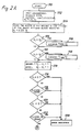
- Figures 2A to 2E represent a flow diagram of a method according to the invention of filling a rectangular surface part with a surface pattern.
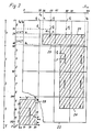
- the basic idea of the method will first be explained by reference to the example illustrated in Fig. 3.
- Fig. 3 illustrates a page 22 to be printed, the format being 120 ⁇ 192 pixels.
- Fig. 3 shows a coarser dot raster than is used in practice.
- Two adjacent rectangular surface parts 24 and 26 are to be filled with the surface pattern already indicated in Fig. 3 without the surface pattern shifting at the boundary between the surface parts 24 and 26.
- the surface part 24 is first filled and then the method is used to fill the surface part 26.
- the basic idea of the method of filling a single rectangular surface part is that first the entire surface of the page 22 is filled with the surface pattern and then those areas which do not belong to that surface part are covered by means of a mask. When a large number of rectangular surface parts have been successively filled with the same pattern in this way, it is ensured that the pattern proceeds continuously at the boundaries between the surface parts. If the surface parts overlap, then the surface patterns in the overlap area are situated exactly one upon the other, thus giving a continuous pattern on the printed page.
- Fig. 3 shows a basic pattern block 28 which contains the pattern to be filled in in the surface parts 24 and 26.
- the entire page 22 is sub-divided into a 4 ⁇ 4 block matrix, each matrix element corresponding to the basic pattern block 28.
- 16 basic pattern blocks all corresponding to the basic pattern block 28 are connected up in accordance with the block matrix, a continuous surface pattern is formed which fills the entire page 22.
- the basic pattern block has a format of 30 ⁇ 48 pixels.
- Various basic patterns e.g. cross-hatching, dot gratings or line gratings of different line thicknesses or spacing or extending in different directions, are stored in the pattern memory 13 or in the RAM 12.
- any desired periodic surface pattern can be stored in this way.
- the various basic patterns may have different dimensions. There is a limitation in the example described only to the extent that the height of the basic pattern in pixels must be a multiple of 16.
- the operation of the raster-image-processor 15 in the filling of the surface part 34 with a surface pattern according to the basic pattern 28 will now be explained with reference to Figures 2A to 2E.
- a variable overlay type indicates in a specific code the logic operation (e.g. PAINT) to be performed by the logic unit of the raster-image-memory 16.
- a basic pattern e.g. the basic pattern 28 shown in Fig. 3 present in the pattern memory is selected by means of the variable "pattern identification".
- the width W and the height H of the basic pattern block 28 selected by means of the "pattern identification" is read in field 104 in Fig. 2A.
- x1 is greater than x2
- y1 and y2 are exchanged correspondingly if y1 is greater than y2 (steps 110 and 112). This ensures that the surface part 24 is defined by the top left corner point and by the bottom right corner point.
- a test is carried out to check whether the boundaries of the surface part lie in the format DIMX ⁇ DIMY of page 22. Since the pixels which form the boundaries of the surface part 24 are also counted as belonging to the surface part, the difference between the coordinate values must be increased by 1 each time in the calculation of the height and the width of the surface part in step 114. If one of said boundaries of the surface part 24 falls outside the page format, an error signal is generated in step 124.
- a variable "pattern offset" is calculated in step 126 in Fig. 2B. This variable indicates the value by which the address of the raster-image-memory must be increased when a jump is carried out over the width W of the basic pattern (i.e.
- DIV denotes a division followed by the formation of a whole number of the quotient.
- the "base-address" value is a provisional value for the addresses in the raster-image-memory 16.
- Mask1 is thus a 16-bit word which in the first ten binary places contains only zeroes and in the other six binary places only ones.
- mask1 is placed, for example, on position M in the raster-image-memory in accordance with the word division of raster-image-memory 16 all the zeroes are situated outside the surface part 24 and the associated ones within the surface part.
- Mask2 is the corresponding mask function for the bottom boundary of the surface part 24.
- y2 MOD 16 13.
- Mask2 is a 16-bit word, in which the first 13 binary places contain the value 1 and the last 3 binary places the value 0.
- To form the mask function "mask”, mask1 and mask2 are combined per element by a logic AND-operation.
- the corresponding 16-bit word would, in the example, have the value 0 at the binary places 1 to 10, the value 1 at the places 11 to 13, and the value 0 at the places 14 to 16.
- the mask function is required when the top and bottom boundaries of the surface part lie within the same word.
- the values y1* and y2* respectively denote the top and bottom boundaries of that surface part in words.
- the values Y1 and Y2 indicate in which line of the block matrix the top and bottom boundaries of the surface part respectively lie.
- the values y 1s and y 2s indicate in words those y-coordinates of the top boundary of the block matrix line which contains said top and bottom boundaries respectively of the surface part 24.
- step 134 in Fig. 2B a base address "bitmap-base-address" of the raster-image-memory 16 is calculated.
- the corresponding point of page 22 is denoted by P2 in Fig. 3 and lies in the top left hand corner of the block matrix which contains the point (x1, y1).
- the steps 136 to 152 form two loops running one through the other, in which the words of the basic pattern block 28 which are stored in the pattern memory are scanned column-wise and line-wise and are read into the raster-image-memory 16.
- the inner loop formed by steps 140 to 144 corresponds to the scanning of a line of the basic pattern block 28.
- the essential step 140 of this loop contais a sub-program by means of which a 16-bit word P w,h having a column index w and a line index h is called up from the pattern memory and - possibly after a logic operation with a mask function - is imaged on all those blocks of the block matrix at which at least a part of the word called up lies within the surface part 24.
- a 16-bit word P w,h having a column index w and a line index h is called up from the pattern memory and - possibly after a logic operation with a mask function - is imaged on all those blocks of the block matrix at which at least a part of the word called up lies within the surface part 24.
- the base-address "bitmap-base-address" is increased by DIMY in step 150. This corresponds to shifting the point P2 by one pixel in the x-direction.
- the loop 138 to 152 is then traversed again to scan the next column of the basic pattern block 28. When all the columns have been scanned the surface part is completely filled with the surface pattern in accordance with the basic pattern 28 and the method is terminated at step 154.
- step 140 starts at step 154 in Fig. 2C.
- the words P w,h of the basic pattern block 28 are read serially via the VME bus 14. During this the columns of the basic pattern block, starting with the column on the extreme left, are scanned successively from top to bottom.
- the word read at step 158 in the sub-program 140 accordingly has precisely those column and line indices w and h which were previously set in the steps 142 and 146. In the example shown in Fig. 3 it is assumed that it is precisely the word P 20,1 of the basic pattern 28 that is read.
- a parameter X is defined which indicates in pixels what column of page 22 is being processed.
- a further variable address "address" is defined in step 166 and made equal to the "base-address + 1".
- the number + 1 for addition is required because the addresses and data are transferred successively via the raster-image-bus 17, and is not shown in Fig. 3. If the parameter X is less than the left hand boundary x1 of the surface part 24 (step 168), the corresponding word cannot yet be placed in the surface part 24.
- step 170 the address "base-address" is increased by the value pattern-offset (jump from P3 to P4 in Fig. 3) and the parameter X is increased (to 80) in step 172 over the width W of the basic pattern block 28.
- the loop is then traversed again starting with step 164.
- the image F1 of the word P w,h intersects only the top boundary of the surface part 24 and therefore undergoes an AND operation with the mask function mask1 in step 184. As a result, the areas situated outside the surface part 24 are excluded from the image.
- step 180 shows that the image of the word does not lie on the top boundary of the surface part 24
- a check is made in step 186 whether the image lies on the bottom boundary of the surface part 24. If that is the case, the word P w,h is modified in step 188 by means of mask2. In the other case, i.e. if the image of the word is not covered by the surface part 24 at all, the program is continued at step 170 (Fig. 2C). If comparison in step 182 shows that the image of the word intersects both the top boundary y1 and the bottom boundary y2 of the surface part 24, the filling pattern word F is generated in step 190 by omitting the said top and bottom boundary respectively at the word P w,h by means of the mask function mask.
- the filling pattern word F is set aside in the raster-image-memory 16 at address a via the raster-image-bus 17 in step 194.
- Step 170 then proceeds with the next column of the block matrix. If step 174 (Fig. 2C) shows that the surface part to be filled extends over several matrix lines of the block matix, the procedure illustrated in Fig. 2E is carried out.
- step 166 the address "address" in step 166 has a value corresponding to point P4 in Fig. 3. This means that the first block to be processed is the one containing the top left hand corner of the surface part 26.
- step 196 the address a is made equal to the value address + h corresponding to point P6. If the image of the word P w,h (wit a y-coordinate y 1s + h) lies fully within the surface part 26 (step 198), the word P w,h is taken as the filling pattern word F (step 200).
- step 202 If the image of the word intersects the top boundary of the surface part 26 (step 202), the word P w,h is modified with mask1 (step 204).
- the filling pattern word F determined in step 200 or 204 is stored at address a in step 206. If it appears in step 202 that the image of the word lies completely outside the surface part 26 (above the top boundary), the word cannot by set aside in that block. Following step 206 or 202, the next block in the relevant column of the block matrix is processed.
- the address a is increased, in step 208, with a value corresponding to the height H of the basic pattern block 28 (point P7).
- the value Y1 indicates the line of the block matrix of page 22 which contains the top boundary of the surface part 26 and in the example illustrated has the value 0.
- the value Y2 indicates the matrix line which contains the bottom boundary of the surface part 26, and has the value 3 here.
- the image of the word P w,h lies in each case within the surface part 26.
- These blocks are processed successively in a loop formed by steps 212 to 220.
- an index i is defined in step 210, which after each run-through of the loop is increased in step 220 until it reaches the value Y2-1 (step 212).
- the filling pattern word F P w,h is placed in the relevant block in steps 214 and 216, and in step 218 the address a is switched on to the block therebeneath.
- step 222 the block containing the bottom boundary of the surface part 26 is processed starting with step 222.
- the steps 222 to 230 are similar to the steps 198 to 206 for the block containing the top boundary of the surface part.
- step 170 the next column of the block matrix is taken at step 170 (Fig. 2C). If step 164 shows that the column X in which the image of the word P w,h is to be placed lies outside x2 it means that a filling pattern word F corresponding to the word P w,h was placed in all the permissible places of the surface part and the sub-program is terminated with step 232.
- a uniform surface pattern forms which extends over the two surface parts 24 and 26 as will be seen in Fig. 3.
- the surface pattern is not really generated over the entire page 22.
- the surface pattern is generated only in those blocks of page 22 which are overlapped by the surface part to be filled.
- the exact position of the surface pattern is nog defined by the boundaries of the surface part to be filled, but by the block boundaries.
- the relevant part of the block matrix is scanned for each word P w,h which is called up from the pattern memory 13, to enable the word to be deposited at all permissible places.
- T(RIBus) denotes the cycle time of the raster-image-bus 17
- T(SCAN) the processing time required for the changeover from a column of the block matrix to the next column.
- the raster-image-processor 15 comprises an address sequencer (2910A of Messrs. Advanced Micro Devices), by means of which the loop, consisting of steps 212 to 220 in Fig. 2E, for filling in the blocks in one and the same column of the block matrix can be completed very quickly.
- the blocks of one and the same column can accordingly be processed within the cycle time of the raster-image-bus 17 so that no extra computing time is necessary for this.
- T(RIBus) of the raster-image-bus 17 is usually considerably less than the cycle time T(VME) of the VME bus, the method according to the invention gives a considerable saving in time.
- T(VME) is about 1 ⁇ sec. while T(RIBus) and T(SCAN) are about 400 nsec. Consequently:
- the ratio T2/T1 is represented graphically in Fig. 4 for various values of W/x.
- T2 is smaller than T1 if the height y of the surface part to be filled is at least 0.5 to 2 times the height H of the basic pattern block.
- a normal basic pattern block has a width of 6 pixels and a height of 48 pixels which corresponds to a height of about 2.4 mm.
- the height of the surface part to be filled is much greater then the height of the basic pattern block, so that the method according to the invention has advantages.
- the invention is not limited to the embodiment described. Using a com parable method it is possible, for example, to fill surface parts which are not rectangular. The skilled addressee can make all kinds of modifications to the example described but they all come under the following claims.
Landscapes
- Physics & Mathematics (AREA)
- General Physics & Mathematics (AREA)
- Engineering & Computer Science (AREA)
- Theoretical Computer Science (AREA)
- Image Generation (AREA)
- Controls And Circuits For Display Device (AREA)
- Dot-Matrix Printers And Others (AREA)
- Laser Beam Printer (AREA)
Applications Claiming Priority (2)
| Application Number | Priority Date | Filing Date | Title |
|---|---|---|---|
| NL8601488 | 1986-06-09 | ||
| NL8601488A NL8601488A (nl) | 1986-06-09 | 1986-06-09 | Werkwijze voor het opvullen van oppervlaktedelen van een afbeelding met een oppervlaktepatroon. |
Publications (1)
| Publication Number | Publication Date |
|---|---|
| EP0249285A1 true EP0249285A1 (de) | 1987-12-16 |
Family
ID=19848145
Family Applications (1)
| Application Number | Title | Priority Date | Filing Date |
|---|---|---|---|
| EP87201056A Ceased EP0249285A1 (de) | 1986-06-09 | 1987-06-05 | Verfahren und Vorrichtung zum Füllen von Bildoberflächenteilen mit einem Oberflächenmuster |
Country Status (4)
| Country | Link |
|---|---|
| US (1) | US4887228A (de) |
| EP (1) | EP0249285A1 (de) |
| JP (1) | JPS62296281A (de) |
| NL (1) | NL8601488A (de) |
Cited By (3)
| Publication number | Priority date | Publication date | Assignee | Title |
|---|---|---|---|---|
| EP0280320A3 (en) * | 1987-02-27 | 1990-11-14 | Nec Corporation | Graphics display controller equipped with boundary searching circuit |
| EP0809212A1 (de) * | 1996-05-20 | 1997-11-26 | Brother Kogyo Kabushiki Kaisha | Druckvorrichtung |
| EP0886243A3 (de) * | 1997-06-18 | 2000-01-12 | Hewlett-Packard Company | Drucker mit Verfahren zum Kacheln und Skalieren von Mustern |
Families Citing this family (15)
| Publication number | Priority date | Publication date | Assignee | Title |
|---|---|---|---|---|
| JPH07118024B2 (ja) * | 1988-01-30 | 1995-12-18 | 株式会社東芝 | パターンデータ生成方式 |
| JPH02231687A (ja) * | 1989-03-06 | 1990-09-13 | Brother Ind Ltd | 描画データ作成装置 |
| US5271093A (en) * | 1989-10-17 | 1993-12-14 | Mitsubishi Denki Kabushiki Kaisha | Video display apparatus for filling the interior shapes of contour |
| US5194969A (en) * | 1990-12-04 | 1993-03-16 | Pixar | Method for borderless mapping of texture images |
| US5579410A (en) * | 1992-10-09 | 1996-11-26 | Mitsubishi Electric Semiconductor Software Corporation | Region filling circuit and method of filling a region |
| US5461703A (en) * | 1992-10-13 | 1995-10-24 | Hewlett-Packard Company | Pixel image edge enhancement method and system |
| US5519413A (en) * | 1993-11-19 | 1996-05-21 | Honeywell Inc. | Method and apparatus for concurrently scanning and filling a memory |
| US6091507A (en) | 1994-07-01 | 2000-07-18 | Colorspan Corporation | Method and apparatus for printing a document over a network |
| US5577172A (en) * | 1994-07-01 | 1996-11-19 | Lasermaster Corporation | High-capacity protocol for packet-based networks |
| US5668941A (en) * | 1995-06-22 | 1997-09-16 | Cirrus Logic, Inc. | Optimum implementation of X-Y clipping on pixel boundary |
| JP3109421B2 (ja) * | 1995-09-08 | 2000-11-13 | 富士ゼロックス株式会社 | 図表処理装置 |
| US6173211B1 (en) | 1998-04-15 | 2001-01-09 | Gerber Technology, Inc. | Apparatus and method for fabric printing of nested |
| US7162387B2 (en) * | 2001-06-29 | 2007-01-09 | National Instruments Corporation | Measurement system graphical user interface for easily configuring measurement applications |
| US6897863B2 (en) * | 2001-11-30 | 2005-05-24 | Caterpillar Inc | System and method for hidden object removal |
| US6744434B2 (en) | 2001-11-30 | 2004-06-01 | Caterpillar Inc | Cuts removal system for triangulated CAD Models |
Citations (4)
| Publication number | Priority date | Publication date | Assignee | Title |
|---|---|---|---|---|
| US4300206A (en) * | 1977-06-30 | 1981-11-10 | International Business Machines Corporation | Flexible text and image generator for a raster printer |
| EP0158902A2 (de) * | 1984-03-30 | 1985-10-23 | Wang Laboratories Inc. | Monochromatische Darstellung von Farbbildern |
| EP0174809A2 (de) * | 1984-09-06 | 1986-03-19 | Tektronix, Inc. | Schnelle Musterfüllung für eine graphische Anzeige mit einem nicht angezeigten Rasterpufferspeicher |
| NL8503461A (nl) * | 1985-12-17 | 1986-04-01 | Oce Nederland Bv | Werkwijze voor het genereren van lijnstukken. |
Family Cites Families (8)
| Publication number | Priority date | Publication date | Assignee | Title |
|---|---|---|---|---|
| US4225861A (en) * | 1978-12-18 | 1980-09-30 | International Business Machines Corporation | Method and means for texture display in raster scanned color graphic |
| US4481594A (en) * | 1982-01-18 | 1984-11-06 | Honeywell Information Systems Inc. | Method and apparatus for filling polygons displayed by a raster graphic system |
| US4615013A (en) * | 1983-08-02 | 1986-09-30 | The Singer Company | Method and apparatus for texture generation |
| US4695966A (en) * | 1984-03-22 | 1987-09-22 | Sharp Kabushiki Kaisha | Image processing device |
| JPS60220387A (ja) * | 1984-04-13 | 1985-11-05 | インタ−ナショナル ビジネス マシ−ンズ コ−ポレ−ション | ラスタ走査表示装置 |
| US4725831A (en) * | 1984-04-27 | 1988-02-16 | Xtar Corporation | High-speed video graphics system and method for generating solid polygons on a raster display |
| IL73961A (en) * | 1984-12-28 | 1989-09-28 | Lantas Dev & Ind Ltd | Fluid actuator devices |
| US4692880A (en) * | 1985-11-15 | 1987-09-08 | General Electric Company | Memory efficient cell texturing for advanced video object generator |
-
1986
- 1986-06-09 NL NL8601488A patent/NL8601488A/nl not_active Application Discontinuation
-
1987
- 1987-06-05 EP EP87201056A patent/EP0249285A1/de not_active Ceased
- 1987-06-08 US US07/059,048 patent/US4887228A/en not_active Expired - Lifetime
- 1987-06-09 JP JP62143951A patent/JPS62296281A/ja active Pending
Patent Citations (4)
| Publication number | Priority date | Publication date | Assignee | Title |
|---|---|---|---|---|
| US4300206A (en) * | 1977-06-30 | 1981-11-10 | International Business Machines Corporation | Flexible text and image generator for a raster printer |
| EP0158902A2 (de) * | 1984-03-30 | 1985-10-23 | Wang Laboratories Inc. | Monochromatische Darstellung von Farbbildern |
| EP0174809A2 (de) * | 1984-09-06 | 1986-03-19 | Tektronix, Inc. | Schnelle Musterfüllung für eine graphische Anzeige mit einem nicht angezeigten Rasterpufferspeicher |
| NL8503461A (nl) * | 1985-12-17 | 1986-04-01 | Oce Nederland Bv | Werkwijze voor het genereren van lijnstukken. |
Cited By (5)
| Publication number | Priority date | Publication date | Assignee | Title |
|---|---|---|---|---|
| EP0280320A3 (en) * | 1987-02-27 | 1990-11-14 | Nec Corporation | Graphics display controller equipped with boundary searching circuit |
| EP0809212A1 (de) * | 1996-05-20 | 1997-11-26 | Brother Kogyo Kabushiki Kaisha | Druckvorrichtung |
| US6062750A (en) * | 1996-05-20 | 2000-05-16 | Brother Kogyo Kabushiki Kaisha | Printer capable of printing a background in addition to text on a tape along with a decorating feature to extend the border of the printed tape |
| EP0886243A3 (de) * | 1997-06-18 | 2000-01-12 | Hewlett-Packard Company | Drucker mit Verfahren zum Kacheln und Skalieren von Mustern |
| US6091418A (en) * | 1997-06-18 | 2000-07-18 | Hewlett-Packard Company | Printer with procedure for pattern tiling and scaling |
Also Published As
| Publication number | Publication date |
|---|---|
| JPS62296281A (ja) | 1987-12-23 |
| US4887228A (en) | 1989-12-12 |
| NL8601488A (nl) | 1988-01-04 |
Similar Documents
| Publication | Publication Date | Title |
|---|---|---|
| EP0249285A1 (de) | Verfahren und Vorrichtung zum Füllen von Bildoberflächenteilen mit einem Oberflächenmuster | |
| US5542031A (en) | Halftone computer imager | |
| EP0115584B1 (de) | Bilderzeugungsapparat und Verarbeitungsverfahren für Bilddarstellungssignale zur Verwendung bei einem derartigen Apparat | |
| US4581710A (en) | Method of editing dot pattern data for character and/or image representations | |
| US5526476A (en) | Method and apparatus for generating character patterns expressed by coordinates of a coordinate system | |
| EP0229412B1 (de) | Verfahren zum Generieren von Linienteilen | |
| JPH0352878B2 (de) | ||
| EP0132415B1 (de) | Drucksystem für einen Punktdrucker | |
| EP0207789A2 (de) | Gerät und Verfahren zur Aufzeichnung vergrösserter Punktmatrix-Zeichen | |
| US4627097A (en) | Method and apparatus for improved printing in a selected orientation | |
| US4555763A (en) | Method and apparatus for storage and accessing of characters, and electronic printer employing same | |
| EP0382293A1 (de) | Verfahren und Gerät zur Umwandlung der Auflösung eines Bildes mit Muster aus bivalenten Pixeln | |
| EP0248262B1 (de) | Gerät und Verfahren zur Ermittlung von Zeichenteilen auf einem gedruckten Dokument | |
| US5073956A (en) | Apparatus for converting image outline data into dot data representative of dots to be formed | |
| JP3111639B2 (ja) | 連続模様印刷システム | |
| US5233441A (en) | Method for representing halftone dots with dot envelope parameters | |
| EP0476627B1 (de) | Verfahren und Einrichtung zur Verarbeitung von Bilddaten | |
| EP0091124B1 (de) | Videosignalerzeugerkreis | |
| EP0100872A2 (de) | Einrichtung und Verfahren zum Vergrössern von Zeichenmustern | |
| EP0267732B1 (de) | Schriftartumsetzungssystem | |
| JP3829908B2 (ja) | 画像処理装置 | |
| KR910005779B1 (ko) | 인자도트수를 감소시키기 위한 프린터의 제어방법 | |
| JPH049152B2 (de) | ||
| EP0639024A1 (de) | Gerät und Verfahren zur Reproduktionsbildrasterung | |
| JPH0366157B2 (de) |
Legal Events
| Date | Code | Title | Description |
|---|---|---|---|
| PUAI | Public reference made under article 153(3) epc to a published international application that has entered the european phase |
Free format text: ORIGINAL CODE: 0009012 |
|
| AK | Designated contracting states |
Kind code of ref document: A1 Designated state(s): AT BE CH DE FR GB IT LI NL SE |
|
| 17P | Request for examination filed |
Effective date: 19880511 |
|
| 17Q | First examination report despatched |
Effective date: 19890825 |
|
| STAA | Information on the status of an ep patent application or granted ep patent |
Free format text: STATUS: THE APPLICATION HAS BEEN REFUSED |
|
| 18R | Application refused |
Effective date: 19910309 |
|
| PGFP | Annual fee paid to national office [announced via postgrant information from national office to epo] |
Ref country code: LU Payment date: 19930602 Year of fee payment: 5 |
|
| EPTA | Lu: last paid annual fee | ||
| RIN1 | Information on inventor provided before grant (corrected) |
Inventor name: ROBERT, ROB WILLEM |