EP0249839A2 - Installation de transport par câble, notamment téléphérique - Google Patents
Installation de transport par câble, notamment téléphérique Download PDFInfo
- Publication number
- EP0249839A2 EP0249839A2 EP87108227A EP87108227A EP0249839A2 EP 0249839 A2 EP0249839 A2 EP 0249839A2 EP 87108227 A EP87108227 A EP 87108227A EP 87108227 A EP87108227 A EP 87108227A EP 0249839 A2 EP0249839 A2 EP 0249839A2
- Authority
- EP
- European Patent Office
- Prior art keywords
- friction
- tire
- cable
- wheel
- conveyor system
- Prior art date
- Legal status (The legal status is an assumption and is not a legal conclusion. Google has not performed a legal analysis and makes no representation as to the accuracy of the status listed.)
- Granted
Links
- 238000009434 installation Methods 0.000 title 1
- 230000002093 peripheral effect Effects 0.000 claims description 13
- 239000000969 carrier Substances 0.000 claims 1
- 238000005299 abrasion Methods 0.000 abstract description 2
- 230000005540 biological transmission Effects 0.000 description 6
- 230000001133 acceleration Effects 0.000 description 2
- 235000004443 Ricinus communis Nutrition 0.000 description 1
- 240000000528 Ricinus communis Species 0.000 description 1
- 230000006835 compression Effects 0.000 description 1
- 238000007906 compression Methods 0.000 description 1
- 230000008878 coupling Effects 0.000 description 1
- 238000010168 coupling process Methods 0.000 description 1
- 238000005859 coupling reaction Methods 0.000 description 1
- 230000003247 decreasing effect Effects 0.000 description 1
- 238000000034 method Methods 0.000 description 1
- 230000001960 triggered effect Effects 0.000 description 1
Images
Classifications
-
- B—PERFORMING OPERATIONS; TRANSPORTING
- B61—RAILWAYS
- B61B—RAILWAY SYSTEMS; EQUIPMENT THEREFOR NOT OTHERWISE PROVIDED FOR
- B61B12/00—Component parts, details or accessories not provided for in groups B61B7/00 - B61B11/00
- B61B12/02—Suspension of the load; Guiding means, e.g. wheels; Attaching traction cables
- B61B12/022—Vehicle receiving and dispatching devices
Definitions
- the invention relates to a cable conveyor system, in particular a cable railway according to the preamble of claim 1.
- Friction wheels designed as tire wheels result from the requirement that a vehicle, both in terms of its acceleration and deceleration, must always be controlled by at least one friction wheel, and consequently there must be reliable engagement between its friction plate and this friction wheel.
- the object of the invention is to reduce the friction abrasion and the corresponding friction work while maintaining the simplicity of the drive of the friction wheels.
- the friction wheel following in the direction of movement of the vehicle determines the speed of the friction wheel, while the friction wheel preceding in the direction of movement can temporarily take on the same speed thanks to the one-way clutch.
- the rotation between the friction wheel and the drive member which is made possible by the one-way clutch, is preferably limited in scope, so that a torque can also be transmitted between the friction wheel and the drive member after passing through the free-wheeling region in the reverse direction of rotation.
- the one-way clutch can be designed inexpensively by having drivers which engage in the friction wheel with circumferential play, spring means are provided, for example, in order to keep the drivers in a normal position relative to the friction wheel, or to return them to them after compression.
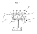
- a cable railway is shown as a cable conveyor.
- the cable conveyor system can also be used for example in foundries, for pallet conveying, etc.
- a conveyor cable of the cable monorail is designated by l, which circulates continuously during operation and connects a valley station designated with A to a mountain station, not shown.
- the cable railway also includes a large number of vehicles, one of which is shown at 2, the vehicles being coupled and suspended on the conveyor cable 1 for transport between the stations.
- the vehicles 2 are supported by means of trolleys 7 of the same on a transfer rail 4 which leads from an entry area B via a 180 ° curved part C to an exit area D.
- Tire wheel sets 5a and 5b are assigned to inlet area B and outlet area D, which have a plurality of tire wheels arranged one behind the other in the direction of movement.
- each undercarriage 7 of each vehicle 2 in addition to castors 7a, which are supported on the transfer rail 4, has two terminals 3 arranged one behind the other, which enable coupling with the conveyor cable 1.
- each undercarriage 7 is equipped with a friction plate 8 running in its longitudinal direction and rigidly connected to it, which extends parallel to the transfer rail.
- the length of the friction plate 8 is somewhat greater than the distance between two adjacent tire wheels 5a and 5b, so that the friction plate is always in engagement with one of the tire wheels in the area of the wheel sets.
- the tire wheels 5a In the inlet area B, the tire wheels 5a have the task of engaging the friction plate with the rope speed braking incoming vehicle, while the tire wheels 5b in the exit area D accelerate the vehicle to the cable speed.
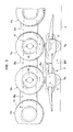
- the individual tire wheels 5a and 5b of each set are driven at different speeds in the manner described in more detail below.
- the following tire wheels have decreasing speeds in the entry area B of the station in the direction of movement of the vehicles, while in the exit area D the following tire wheels have increasing speeds in the direction of the rope.
- Each tire wheel 5a is connected to a drive member in the form of a V-belt drive 6.
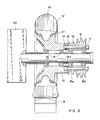
- Each tire wheel 5a comprises a hub l0 with a recess l3, a rim ll and a tire l2.
- Each tire wheel 5a is rotatably supported by means of two roller bearings l8 on an axis l5, which in addition also rotatably supports two pulleys 6a and 6b. All axes l5 of the set of tire wheels 5a are fastened in a common plane parallel to one another on a carrier 20 which in turn runs parallel to the transfer rail 4 in the inlet area B.
- the different diameter pulleys 6a and 6b are connected to each other by two diametrically arranged screws l6 provided with nuts 9, which engage with their heads l6a in diametrically arranged pockets l3a of the recesses l3 in the hub l0.
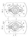
- a prestressed return spring l4 is also inserted in the recess l3 or one of the pockets l3a. 4 and 5, the return spring l4 forms two loops l4a, l4b, of which the smaller loop l4a loops around the head l6a of one of the two screws l6.
- the larger loop l4b The return spring l4 loops around the axis l5 of the tire wheel 5a at a distance and is supported with its end l4c at l0a on the hub l0.
- the drive members or V-belt transmission 6 are connected to their tire wheels 5a via a one-way clutch, which is formed by the pockets l3a and the screw heads l6a.
- a one-way clutch which is formed by the pockets l3a and the screw heads l6a.
- screws l6 acting as drivers engage with their heads l6a with play in the pockets l3a of the hub l0 and allow the tire wheels 5a to be rotated relative to the drive members by the angle ⁇ (FIG. 5 ) too.
- Such a rotation from the normal position shown in FIG. 5 in the direction of the end position shown in FIG. 4 is only possible in one direction of rotation and only against the action of the prestressed spring 14.
- the tire wheels 5a and 5b of the two wheel sets of station A are driven by a drive motor denoted by M, which also drives the conveying rope 1 via a rope pulley 1a wrapped around it.
- the motor M is connected via a gearbox G and transmission shafts T to the sheave la and the tire wheels 5a ⁇ and 5b ⁇ , these being the first tire wheel 5a of the inlet area B and the last tire wheel of the outlet area D.
- the transmission G these two tire wheels 5a ⁇ and 5b ⁇ get a peripheral speed which is the peripheral speed of the Pulley la and thus the speed of the conveyor cable l is the same.
- each V-belt transmission comprises a V-belt 6c, which connects the smaller pulley 6a of a tire wheel 5a or 5b with the larger pulley 6b of the left-hand tire wheel 5a or 5b.
- the speeds of the individual tire wheels 5a and 5b therefore decrease with increasing distance from the tire wheels 5a ⁇ and 5b ⁇ .
- a vehicle 2 entering the station A is gradually decelerated by the action of the tire wheels 5a on the friction plate 8.
- the tire wheels 5b gradually accelerate a vehicle 2 in the run-out area D until the latter has reached the rope speed through the last wheel and can then be coupled with the rope 1 without jolts by closing the clamps 3.
- this tire wheel takes the undercarriage on the transfer rail 4 with it.
- the friction plate 8 exerts a frictional force on the preceding tire wheel 5b driven by its V-belt transmission 6 at a lower peripheral speed. Thanks to the freewheel, the corresponding preceding tire wheel can now accelerate to the speed of movement of the friction plate 8 and thus advance its V-belt drive while rotating the parts against the action of the return spring 14 in the direction of the end position shown in FIG. 4. However, as soon as the friction plate 8 has come out of engagement with this preceding tire wheel, the return spring 14 rotates the same back into the position in which the parts of the clutch assume the normal position according to FIG. 5.
- the one-way clutches have the same function on the tire wheels 5a of the inlet section B.
- the one-way clutch is installed in such a way that the wheel following in the direction of movement - here the tire wheel driven at a lower peripheral speed - determines the speed of the preceding tire wheel which is engaged with the same friction plate.
- the previous tire wheel in the direction of movement is also decelerated until it comes out of engagement with the friction plate.
- the V-belt drive runs ahead of its tire.
- the angle ⁇ is chosen as a function of the amount by which the engagement distance of the friction plate 8, given by length and design, is greater than the distance between two tire wheels or their axes. It has been shown that an angle ⁇ of somewhat 10 ° is sufficient to end the simultaneous engagement of two tire wheels before reaching the end position according to FIG. 4. The end position according to Fig. 4 is only reached if e.g. In the event of a fault, the tire wheels should be driven in the opposite direction of rotation in order to move vehicles backwards.
- the friction plate 8 can be made of plastic and can be provided on the friction surface with elevations, e.g. be provided with transverse ribs.
- part of the tire wheels 5a at the end of the inlet section B and at the beginning of the outlet section D is driven at the same speed. Accordingly, no one-way clutch is required between these tire wheels and their drive members.
Landscapes
- Engineering & Computer Science (AREA)
- Transportation (AREA)
- Mechanical Engineering (AREA)
- Tires In General (AREA)
- Medicines Containing Material From Animals Or Micro-Organisms (AREA)
- Acyclic And Carbocyclic Compounds In Medicinal Compositions (AREA)
- Detergent Compositions (AREA)
- Ropes Or Cables (AREA)
- Details Of Indoor Wiring (AREA)
- Lubricants (AREA)
- Devices For Conveying Motion By Means Of Endless Flexible Members (AREA)
- Pulleys (AREA)
- Transmissions By Endless Flexible Members (AREA)
- Mechanical Operated Clutches (AREA)
- Braking Arrangements (AREA)
Priority Applications (1)
| Application Number | Priority Date | Filing Date | Title |
|---|---|---|---|
| AT87108227T ATE59021T1 (de) | 1986-06-17 | 1987-06-06 | Seilfoerderanlage, insbesondere seilschwebebahn. |
Applications Claiming Priority (2)
| Application Number | Priority Date | Filing Date | Title |
|---|---|---|---|
| CH2468/86 | 1986-06-17 | ||
| CH2468/86A CH671552A5 (fr) | 1986-06-17 | 1986-06-17 |
Publications (3)
| Publication Number | Publication Date |
|---|---|
| EP0249839A2 true EP0249839A2 (fr) | 1987-12-23 |
| EP0249839A3 EP0249839A3 (en) | 1988-03-23 |
| EP0249839B1 EP0249839B1 (fr) | 1990-12-12 |
Family
ID=4234495
Family Applications (1)
| Application Number | Title | Priority Date | Filing Date |
|---|---|---|---|
| EP87108227A Expired - Lifetime EP0249839B1 (fr) | 1986-06-17 | 1987-06-06 | Installation de transport par câble, notamment téléphérique |
Country Status (9)
| Country | Link |
|---|---|
| US (1) | US4794864A (fr) |
| EP (1) | EP0249839B1 (fr) |
| JP (1) | JPS632765A (fr) |
| AT (1) | ATE59021T1 (fr) |
| CA (1) | CA1278545C (fr) |
| CH (1) | CH671552A5 (fr) |
| DE (1) | DE3766657D1 (fr) |
| HK (1) | HK98191A (fr) |
| NO (1) | NO166773C (fr) |
Cited By (5)
| Publication number | Priority date | Publication date | Assignee | Title |
|---|---|---|---|---|
| EP0433703A1 (fr) * | 1989-12-21 | 1991-06-26 | Von Roll Seilbahnen AG | Transporteur aérien |
| EP0507699A1 (fr) * | 1991-04-02 | 1992-10-07 | Pomagalski S.A. | Dispositif d'entraînement de véhicules par des roues de friction |
| CH681507A5 (en) * | 1989-12-21 | 1993-04-15 | Lasag Ag | Lens contacting eye for medical treatment |
| US5402730A (en) * | 1993-08-11 | 1995-04-04 | The Walt Disney Company | Platen drive unit |
| EP1987998A1 (fr) * | 2007-04-24 | 2008-11-05 | Innova Patent GmbH | Agencement d'entraînement pour téléphériques et unité de freinage et d'embrayage correspondant |
Families Citing this family (14)
| Publication number | Priority date | Publication date | Assignee | Title |
|---|---|---|---|---|
| JP2530466Y2 (ja) * | 1990-04-13 | 1997-03-26 | 日本ケーブル株式会社 | 自動循環式索道の加速及び減速移送装置 |
| FR2661147B1 (fr) * | 1990-04-24 | 1992-07-24 | Pomagalski Sa | Station d'extremite de tension d'un teleporteur. |
| FR2669286B1 (fr) * | 1990-11-15 | 1993-02-19 | Pomagalski Sa | Teleporteur a vehicules entraines par friction dans les zones de contournement. |
| US5158020A (en) * | 1991-05-10 | 1992-10-27 | Zygmunt Alexander Kunczynski | Drive shoe assembly with resiliently flexible traction members and method |
| FR2740417B1 (fr) * | 1995-10-25 | 1998-01-02 | Pomagalski Sa | Teleporteur debrayable a module de prise de mouvement |
| AT405270B (de) * | 1995-11-14 | 1999-06-25 | Doppelmayr & Sohn | Seilbahnanlage |
| AT409256B (de) * | 1999-01-27 | 2002-07-25 | High Technology Invest Bv | Einrichtung zur notbremsung von transportmitteln |
| US7300237B2 (en) * | 2004-11-22 | 2007-11-27 | Inventio Ag | Self-locking bolted fastener |
| US20070034105A1 (en) * | 2005-08-09 | 2007-02-15 | Jean-Francois Mugnier | Aerial ropeway transport methods |
| AT503502A3 (de) * | 2006-03-23 | 2010-07-15 | Innova Patent Gmbh | Verfahren zum betrieb einer seilbahnanlage und seilbahnanlage |
| FR2899191B1 (fr) * | 2006-04-04 | 2008-05-30 | Denis Creissels Consultant Sar | Installation de telecabines automatiques |
| FR2899549B1 (fr) * | 2006-04-10 | 2008-06-27 | Pomagalski Sa | Installation de transport a cable aerien vehiculant des sieges et des cabines |
| EP2213543A1 (fr) * | 2009-01-29 | 2010-08-04 | Innova Patent GmbH | Poulie à courroie pour un téléphérique et son bloc de fabrication |
| IT201700036544A1 (it) * | 2017-04-03 | 2018-10-03 | Leitner Spa | Stazione per un impianto di trasporto a fune, impianto di trasporto a fune comprendente tale stazione e metodo di funzionamento di tale impianto di trasporto a fune |
Family Cites Families (14)
| Publication number | Priority date | Publication date | Assignee | Title |
|---|---|---|---|---|
| FR1401291A (fr) * | 1964-04-15 | 1965-06-04 | Neyrpic Ets | Dispositif de réception en gare des véhicules de téléphériques |
| US3429279A (en) * | 1966-12-20 | 1969-02-25 | Jean Pomagalski | Device for supporting and guiding the cable of an aerial cableway |
| DE2162127A1 (de) * | 1971-11-29 | 1973-06-20 | Merlin Gerin Grenoble | Synchronisationsvorrichtung fuer eine befoerderungsanlage |
| FR2094270A5 (fr) * | 1970-06-15 | 1972-02-04 | Merlin Gerin | |
| US4003314A (en) * | 1975-04-25 | 1977-01-18 | Pearson William F | Ski lift monitoring |
| US4050385A (en) * | 1975-09-29 | 1977-09-27 | Walt Disney Productions | High capacity passenger transport apparatus |
| IT1055250B (it) * | 1976-02-12 | 1981-12-21 | Agudio Off Mec | Gruppo di lancio e di rallentamento di veicoli di trasporto a fune |
| US4187784A (en) * | 1977-03-07 | 1980-02-12 | Fernandez Arthur A | Self propelled cable car |
| FR2450187A1 (fr) * | 1979-02-27 | 1980-09-26 | Ogoque Cie Miniere Comilog | Dispositif de stabilisation de vitesse pour installation de transport a cable aerien |
| FR2539369B1 (fr) * | 1983-01-17 | 1986-03-07 | Pomagalski Sa | Dispositif cadenceur pour telecabine ou telesiege debrayable |
| FR2548613B1 (fr) * | 1983-07-06 | 1985-11-15 | Pomagalski Sa | Dispositif de degagement d'une traverse d'entrainement par friction d'une pince de telesiege |
| FR2571675B1 (fr) * | 1984-10-15 | 1988-03-18 | Pomagalski Sa | Installation de transport a cable aerien a plusieurs sections |
| FR2571674B1 (fr) * | 1984-10-15 | 1988-05-06 | Pomagalski Sa | Telecabine ou telesiege debrayable a transmission electrique |
| DE3575104D1 (de) * | 1985-01-04 | 1990-02-08 | Pomagalski Sa | Seilschwebebahn. |
-
1986
- 1986-06-17 CH CH2468/86A patent/CH671552A5/de not_active IP Right Cessation
-
1987
- 1987-06-06 DE DE8787108227T patent/DE3766657D1/de not_active Expired - Lifetime
- 1987-06-06 EP EP87108227A patent/EP0249839B1/fr not_active Expired - Lifetime
- 1987-06-06 AT AT87108227T patent/ATE59021T1/de not_active IP Right Cessation
- 1987-06-12 JP JP62146833A patent/JPS632765A/ja active Pending
- 1987-06-15 US US07/061,623 patent/US4794864A/en not_active Expired - Fee Related
- 1987-06-16 NO NO872511A patent/NO166773C/no unknown
- 1987-06-16 CA CA000539759A patent/CA1278545C/fr not_active Expired - Lifetime
-
1991
- 1991-12-05 HK HK981/91A patent/HK98191A/xx unknown
Cited By (7)
| Publication number | Priority date | Publication date | Assignee | Title |
|---|---|---|---|---|
| EP0433703A1 (fr) * | 1989-12-21 | 1991-06-26 | Von Roll Seilbahnen AG | Transporteur aérien |
| US5121695A (en) * | 1989-12-21 | 1992-06-16 | Von Roll Transportsysteme Ag | Overhead cableway |
| CH681507A5 (en) * | 1989-12-21 | 1993-04-15 | Lasag Ag | Lens contacting eye for medical treatment |
| EP0507699A1 (fr) * | 1991-04-02 | 1992-10-07 | Pomagalski S.A. | Dispositif d'entraînement de véhicules par des roues de friction |
| FR2674807A1 (fr) * | 1991-04-02 | 1992-10-09 | Pomagalski Sa | Dispositif d'entrainement de vehicules par des roues de friction. |
| US5402730A (en) * | 1993-08-11 | 1995-04-04 | The Walt Disney Company | Platen drive unit |
| EP1987998A1 (fr) * | 2007-04-24 | 2008-11-05 | Innova Patent GmbH | Agencement d'entraînement pour téléphériques et unité de freinage et d'embrayage correspondant |
Also Published As
| Publication number | Publication date |
|---|---|
| US4794864A (en) | 1989-01-03 |
| CA1278545C (fr) | 1991-01-02 |
| NO872511D0 (no) | 1987-06-16 |
| ATE59021T1 (de) | 1990-12-15 |
| NO166773C (no) | 1991-09-04 |
| EP0249839B1 (fr) | 1990-12-12 |
| EP0249839A3 (en) | 1988-03-23 |
| DE3766657D1 (de) | 1991-01-24 |
| HK98191A (en) | 1991-12-13 |
| NO872511L (no) | 1987-12-18 |
| CH671552A5 (fr) | 1989-09-15 |
| NO166773B (no) | 1991-05-27 |
| JPS632765A (ja) | 1988-01-07 |
Similar Documents
| Publication | Publication Date | Title |
|---|---|---|
| EP0249839B1 (fr) | Installation de transport par câble, notamment téléphérique | |
| EP0930248B1 (fr) | Dispositif de tri d'articles | |
| DE102007040859B4 (de) | Querbandsorter zum Transportieren und Sortieren von Stückgut und Verfahren zum Antrieb eines Querbandsorters zum Transportieren und Sortieren von Stückgut | |
| DE2411686B2 (de) | Rad-schienenanordnung fuer schienenfahrzeuge mit spurkranzlosen tragraedern | |
| EP0151965B1 (fr) | Chemin de fer électrique suspendu | |
| EP0275403A1 (fr) | Installation de téléphérique | |
| EP0355084A1 (fr) | Installation de téléphérage comportant des poulies de retour de câble dans les stations hautes et basses | |
| CH672765A5 (fr) | ||
| DE2356876A1 (de) | Mit veraenderlicher geschwindigkeit antreibbares fahrzeug fuer ein transportsystem | |
| DE10333938B3 (de) | Fördereinrichtung, insbesondere Hängefördereinrichtung | |
| DE3124898C2 (de) | Vorrichtung zum Überführen und Umlenken von Paletten | |
| EP1029815A1 (fr) | Dispositif de transport ou de transmission de force | |
| EP3142914B1 (fr) | Dispositif de transport pour transporter des marchandises | |
| DE1074068B (de) | Umlaufseilbahn mit vom Zugseil abkuppelbaren Wagen | |
| DE950174C (de) | Endloser Zwischenantrieb fuer Foerderbaender | |
| DE69502424T2 (de) | Übertragungssystem zur Überführung von Fördereinheiten von einem Flurförderer auf einen anderen und Verfahren zum Holen einer Fördereinheit von einer Haupt- auf eine Nebenkettenstrasse | |
| DE2802401C3 (de) | Hängebahnanlage | |
| CH284669A (de) | Umlaufseilbahn. | |
| DE4131973C2 (de) | Vorrichtung zum Spannen eines endlosen Zugseils | |
| EP0296466B1 (fr) | Poulie | |
| CH372976A (de) | Fördervorrichtung an einer Verarbeitungsmaschine | |
| DE706487C (de) | Einrichtung zur Beherrschung der Bewegung von Foerderwagen, vormehmlich im Untertagebetrieb | |
| DE69612932T2 (de) | Antrieb eines Seilförderers für freifliessende, lose Materialien | |
| DE2223729C3 (de) | Seilablenkvorrichtung für Einseilbahnen | |
| DE1478268C3 (de) | Selbsttätige mechanische Bremsvorrichtung für auf Schienen laufende Wagen einer Belustigungsbahn |
Legal Events
| Date | Code | Title | Description |
|---|---|---|---|
| PUAI | Public reference made under article 153(3) epc to a published international application that has entered the european phase |
Free format text: ORIGINAL CODE: 0009012 |
|
| AK | Designated contracting states |
Kind code of ref document: A2 Designated state(s): AT DE FR GB IT SE |
|
| PUAL | Search report despatched |
Free format text: ORIGINAL CODE: 0009013 |
|
| AK | Designated contracting states |
Kind code of ref document: A3 Designated state(s): AT DE FR GB IT SE |
|
| 17P | Request for examination filed |
Effective date: 19880827 |
|
| 17Q | First examination report despatched |
Effective date: 19890914 |
|
| RAP1 | Party data changed (applicant data changed or rights of an application transferred) |
Owner name: VON ROLL TRANSPORTSYSTEME AG |
|
| GRAA | (expected) grant |
Free format text: ORIGINAL CODE: 0009210 |
|
| AK | Designated contracting states |
Kind code of ref document: B1 Designated state(s): AT DE FR GB IT SE |
|
| REF | Corresponds to: |
Ref document number: 59021 Country of ref document: AT Date of ref document: 19901215 Kind code of ref document: T |
|
| ET | Fr: translation filed | ||
| REF | Corresponds to: |
Ref document number: 3766657 Country of ref document: DE Date of ref document: 19910124 |
|
| ITF | It: translation for a ep patent filed | ||
| GBT | Gb: translation of ep patent filed (gb section 77(6)(a)/1977) | ||
| PLBE | No opposition filed within time limit |
Free format text: ORIGINAL CODE: 0009261 |
|
| STAA | Information on the status of an ep patent application or granted ep patent |
Free format text: STATUS: NO OPPOSITION FILED WITHIN TIME LIMIT |
|
| 26N | No opposition filed | ||
| ITTA | It: last paid annual fee | ||
| PGFP | Annual fee paid to national office [announced via postgrant information from national office to epo] |
Ref country code: GB Payment date: 19940516 Year of fee payment: 8 |
|
| PGFP | Annual fee paid to national office [announced via postgrant information from national office to epo] |
Ref country code: SE Payment date: 19940524 Year of fee payment: 8 |
|
| EAL | Se: european patent in force in sweden |
Ref document number: 87108227.7 |
|
| PGFP | Annual fee paid to national office [announced via postgrant information from national office to epo] |
Ref country code: DE Payment date: 19950518 Year of fee payment: 9 |
|
| PG25 | Lapsed in a contracting state [announced via postgrant information from national office to epo] |
Ref country code: GB Effective date: 19950606 |
|
| PG25 | Lapsed in a contracting state [announced via postgrant information from national office to epo] |
Ref country code: SE Effective date: 19950607 |
|
| GBPC | Gb: european patent ceased through non-payment of renewal fee |
Effective date: 19950606 |
|
| EUG | Se: european patent has lapsed |
Ref document number: 87108227.7 |
|
| PGFP | Annual fee paid to national office [announced via postgrant information from national office to epo] |
Ref country code: FR Payment date: 19960521 Year of fee payment: 10 |
|
| PGFP | Annual fee paid to national office [announced via postgrant information from national office to epo] |
Ref country code: AT Payment date: 19960523 Year of fee payment: 10 |
|
| PG25 | Lapsed in a contracting state [announced via postgrant information from national office to epo] |
Ref country code: DE Effective date: 19970301 |
|
| PG25 | Lapsed in a contracting state [announced via postgrant information from national office to epo] |
Ref country code: AT Effective date: 19970606 |
|
| PG25 | Lapsed in a contracting state [announced via postgrant information from national office to epo] |
Ref country code: FR Free format text: LAPSE BECAUSE OF NON-PAYMENT OF DUE FEES Effective date: 19980227 |
|
| REG | Reference to a national code |
Ref country code: FR Ref legal event code: ST |
|
| REG | Reference to a national code |
Ref country code: FR Ref legal event code: ST |
|
| PG25 | Lapsed in a contracting state [announced via postgrant information from national office to epo] |
Ref country code: IT Free format text: LAPSE BECAUSE OF NON-PAYMENT OF DUE FEES;WARNING: LAPSES OF ITALIAN PATENTS WITH EFFECTIVE DATE BEFORE 2007 MAY HAVE OCCURRED AT ANY TIME BEFORE 2007. THE CORRECT EFFECTIVE DATE MAY BE DIFFERENT FROM THE ONE RECORDED. Effective date: 20050606 |