EP0355084A1 - Installation de téléphérage comportant des poulies de retour de câble dans les stations hautes et basses - Google Patents
Installation de téléphérage comportant des poulies de retour de câble dans les stations hautes et basses Download PDFInfo
- Publication number
- EP0355084A1 EP0355084A1 EP89890194A EP89890194A EP0355084A1 EP 0355084 A1 EP0355084 A1 EP 0355084A1 EP 89890194 A EP89890194 A EP 89890194A EP 89890194 A EP89890194 A EP 89890194A EP 0355084 A1 EP0355084 A1 EP 0355084A1
- Authority
- EP
- European Patent Office
- Prior art keywords
- conveyor
- wheels
- hangers
- speed
- cable
- Prior art date
- Legal status (The legal status is an assumption and is not a legal conclusion. Google has not performed a legal analysis and makes no representation as to the accuracy of the status listed.)
- Withdrawn
Links
- 238000009434 installation Methods 0.000 title claims 8
- 230000008878 coupling Effects 0.000 claims abstract description 12
- 238000010168 coupling process Methods 0.000 claims abstract description 12
- 238000005859 coupling reaction Methods 0.000 claims abstract description 12
- 230000003247 decreasing effect Effects 0.000 claims abstract description 4
- 230000001133 acceleration Effects 0.000 claims description 14
- 230000002093 peripheral effect Effects 0.000 description 4
- 230000005540 biological transmission Effects 0.000 description 2
- 230000007423 decrease Effects 0.000 description 2
- 239000000725 suspension Substances 0.000 description 2
- 230000003111 delayed effect Effects 0.000 description 1
Images

Classifications
-
- B—PERFORMING OPERATIONS; TRANSPORTING
- B61—RAILWAYS
- B61B—RAILWAY SYSTEMS; EQUIPMENT THEREFOR NOT OTHERWISE PROVIDED FOR
- B61B12/00—Component parts, details or accessories not provided for in groups B61B7/00 - B61B11/00
- B61B12/10—Cable traction drives
- B61B12/105—Acceleration devices or deceleration devices other than braking devices
-
- B—PERFORMING OPERATIONS; TRANSPORTING
- B61—RAILWAYS
- B61B—RAILWAY SYSTEMS; EQUIPMENT THEREFOR NOT OTHERWISE PROVIDED FOR
- B61B12/00—Component parts, details or accessories not provided for in groups B61B7/00 - B61B11/00
- B61B12/02—Suspension of the load; Guiding means, e.g. wheels; Attaching traction cables
- B61B12/022—Vehicle receiving and dispatching devices
Definitions
- the invention relates to a cable car system with deflection disks for the conveyor cable located in the valley station and in the mountain station, of which at least one is driven, with hangers such as cabins or armchairs that can be coupled to or disconnected from the conveyor cable, and in at least one of the stations Devices for uncoupling the buckets from the conveyor cable, for conveying the buckets uncoupled from the conveyor rope in the direction of movement of the conveyor rope and for coupling the buckets to the conveyor rope, the conveyor device reducing the speed of the buckets after uncoupling from the conveyor rope in order to leave or climb them to be able to, and before their coupling to the conveyor cable to the speed of the conveyor cable is adjusted.
- the slings coupled with the conveyor rope are uncoupled in the station and guided along a guide rail away from the rope.
- a conveyor chain is assigned to the guide rail, by means of which the hangers from that area in which the rope is uncoupled to that area in which they are coupled to the rope again, are moved.
- the hanger After the hanger has been uncoupled from the rope, they are guided over a plurality of wheels which have circumferential speeds which decrease in the direction of movement of the hanger, as a result of which the speed of the hanger is reduced from the speed of the conveyor rope to the speed at which the hanger leaves the passengers or can be climbed by them.
- the hangers Before the area of the coupling of the hangers to the rope, they are guided over wheels which are driven in the direction of movement of the conveyor rope with increasing peripheral speeds, whereby the speed of the hangers is adapted to the speed of the conveyor rope to such an extent that they can be coupled to the conveyor rope.
- the conveyance of the hangers in their uncoupled state takes place by means of a chain, which are formed at intervals of four to five meters with protruding fingers, through which the hangers are grasped and moved on at the predetermined intervals.
- a chain which are formed at intervals of four to five meters with protruding fingers, through which the hangers are grasped and moved on at the predetermined intervals.
- the invention is therefore based on the object to provide a cable car system through which an individual control of the movement of the hangers is possible in the area between the uncoupling of the hangers from the conveyor cable and the coupling of the hangers, whereby these at equal intervals to the Conveyor rope can be coupled.
- This is achieved according to the invention in that in the area of the conveyor of the buckets uncoupled from the conveyor rope a measuring device is provided to detect the movement of the buckets, by means of which the speed of the drive of the conveyor device can be controlled in such a way that the speed of the buckets increases compared to a normalized speed or can be reduced.
- the drive of the conveyor in the deceleration section or in the acceleration section can be controlled by the measuring device.
- the conveyor device with a between the delay line and the loading acceleration path located control path, the drive of which can be controlled from the measuring device, wherein the measuring device is preferably provided at the end of the delay line of the conveyor.
- the time interval between two successive buckets moved by the conveying device can be detected by the measuring device, whereby the conveying device can be controlled for the buckets in question in such a way that it is at the required distance from the previous buckets.
- the deceleration section and the acceleration section of the conveyor are designed in a manner known per se with wheels, by means of which the speed of the slings guided in the rails can be controlled, the control section located between these two sections also being designed with wheels, the Drive is controllable, with a gear in the drive of the wheels located in the controlled system, by means of which their speed can be controlled as a function of the output signal of the measuring device. All the wheels in the controlled system can be coupled with each other for entrainment, and their drive can be derived via a gear for driving the wheels of the deceleration system or acceleration system.
- the wheels located in the controlled system are driven at reduced or increased speed for the required periods, as a result of which the required deceleration or acceleration of the sling in question is effected.
- the wheels located in the controlled system can be subdivided into groups, the wheels of the individual groups being coupled with one another for entrainment and the drives of which are derived via gears from the drive for the wheels of the deceleration line and / or the wheels of the acceleration line.
- the gears can be formed by shafts driven by means of different gear ratios and couplings assigned to them.
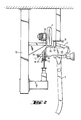
- Fig. 1 of the drawing the station of a cable car system is shown. As can be seen from this, it has a rope pulley 1 with a rope 11 guided around it. In the station there is also a guide rail 2, along which slings 3, after they have been uncoupled from the rope 11, be moved. The movement of the hangers 3 takes place by means of a plurality of wheels 4, 5 and 6, the function of which is explained below.
- the pulley 1 is driven by a motor.
- the individual components are supported by a framework 12.
- the wheels 4, 5 and 6 are mounted on a rail 13.
- the slings 3 entering the station are uncoupled from the conveyor rope 11 and are moved along the rail 2 by means of the wheels 4, 5 and 6, this movement being controlled in such a way that the slings 3 are decelerated by the rope 11 after they have been uncoupled, that they can be left by the passengers or subsequently climbed by other passengers, whereby they are subsequently brought back to a speed corresponding to the speed of the conveyor cable 11, as a result of which they can be coupled to the conveyor cable 11.
- FIG. 2 shows the arrangement of a hanger 3 at the time of uncoupling from the rope 11.
- a lever 31 which acts under the action of a spring and which carries a roller 32 at its free end.
- the lever 31 interacts with a clamp 34, which protrudes from the running apparatus 33 of the hanger 3 and is formed by two jaws and which surrounds the conveyor cable 11.
- the running apparatus 33 is also formed with rollers 35 and with a guide plate 36.
- the wheels 4, 5 and 6 located in the station come into contact with the guide plate 36, by means of which the movement control of the hanger 3 is effected.
- the roller 32 runs onto a guide rail 16, as a result of which the lever 32 is pivoted downward against the action of the spring.
- the jaws of the clamp 34 are moved apart, whereby the clamp 34 is opened.
- the hanger 3 is clamped to the conveyor cable 11 by closing the clamp 34 under the action of the spring.
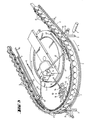
- the rail 2 which surrounds the cable pulley 1 at a distance from it, is located in the station outside the cable pulley 1, around which the conveyor cable 11 is guided.
- uncoupled hangers 3 are guided from the conveyor cable 11.
- the rail 2 is assigned to three groups of wheels 4, 5 and 6, which run onto the guide plate 36 provided on the hanger 3, as a result of which the hanger 3 is moved or its speed is controlled as a function of the peripheral speed of the wheels 4, 5 and 6 .
- a motor 14 is used to drive the wheels 4, 5 and 6.
- the motor 14 is connected to a first gear 43 via a shaft 42.
- One of the wheels 4 is driven directly by the gear 43.
- the remaining wheels 4 are connected to the wheel directly driven by the gear 43 via V-belts 41.
- a shaft 45 extends from the transmission 43, via which the first wheel in the group of wheels 4 is driven.
- wheels 4 form a first group, the drive of which is controlled so that the circumferential speed of the wheels 4 decreases in the direction of movement A of the buckets 2.
- This group of wheels is followed by a further group of wheels 5, which are also coupled with one another for entrainment.
- These wheels 5 are likewise driven by the motor 14, specifically via a shaft 52 to a second gear 53, through which the wheels 5 can be driven at different peripheral speeds.
- the drive shaft 52 is connected to a directly coupled shaft 54.
- Parallel to the shaft 54 are further drive shafts 55 and 56, which are coupled to the shaft 54 with different gear ratios for driving.
- couplings, in particular magnetic couplings 57 are arranged in the shafts 54, 55 and 56.
- the wheels 5 are also directly coupled to one another by means of V-belts 51. Depending on which of the drive shafts 54 to 56 drives the wheels 5, they are moved at a speed that is increased or decreased compared to an average speed.
- the group of wheels 5 is followed by the group of wheels 6, which are likewise coupled to one another by means of belts 61 and which are driven by the motor 14 via a shaft 62 and a third gear 63.
- one of the wheels 6 is driven directly by the gear 63 and is coupled to the other wheels 6 by gear ratios, that the wheels 6 have increasing circumferential speeds in the direction of movement A of the buckets 3.
- the last wheel of the group of wheels 6 is also coupled to the transmission 63 by means of a shaft 65, which is intended to compensate for any slippage caused by the belts 61.
- a measuring device 7 is also provided, through which the passage of each of the hangers 3 is detected.
- this device is as follows: When the hangers 3 enter the station, they are uncoupled from the conveyor cable 11 and guided into the rail 2. In this first area, the uncoupling area, the wheels run onto the guide plate 36 of the hanger 3. Since the wheels 4 are driven in the direction of movement with decreasing peripheral speeds, the speed of the buckets 3 in question is thereby reduced. The speed must be reduced to such a value that the hanger 3 has such a speed approximately in the region of the end of the group of wheels 4 that the hanger 3 can be left. The time interval between two successive hangers 3 is measured by the measuring device 7. If a following hanger 3 is too small a distance from the previous hanger, its movement must subsequently be delayed. However, if a hanger 3 is too far apart from the previous hanger, the movement of this hanger 3 must be accelerated. The drive for the wheels 5 is controlled by the values given by the measuring device 7.
- the group of wheels 5 is driven via the shaft 54 at a medium speed, the drive shafts 55 and 56 being switched off by means of the clutches 57 located therein. If, on the other hand, acceleration or deceleration of the hanger 2 in question is to be effected, the wheels 5 are driven either via the shaft 56 via the shaft 55.
- the hangers 3 reach the area of the wheels 6, by means of which they are accelerated to the speed of the conveyor cable 11, whereupon they are coupled to the conveyor cable 11 at the end of this acceleration section.
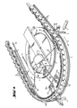
- the wheels are divided into two groups of wheels 5a and 5b in the controlled system, the wheels 5 via the shafts 54a with a predetermined standard speed, via the shaft 55a with an opposite Standard speed reduced speed or can be driven via the shaft 56a with a higher speed than the standard speed.
- the wheels located in the controlled system can be divided into a plurality of groups, each of which can be driven at speeds different from the standard speed, so that the distance from the previous suspension can be corrected during the passage of a suspension 3.
- a part of the wheels in the deceleration section or in the acceleration section in its drive can also be separately controllable in order to regulate the distance between the hangers.
Landscapes
- Engineering & Computer Science (AREA)
- Transportation (AREA)
- Mechanical Engineering (AREA)
- Chain Conveyers (AREA)
- Arrangement And Driving Of Transmission Devices (AREA)
- Platform Screen Doors And Railroad Systems (AREA)
Applications Claiming Priority (2)
| Application Number | Priority Date | Filing Date | Title |
|---|---|---|---|
| AT204988 | 1988-08-18 | ||
| AT2049/88 | 1988-08-18 |
Publications (1)
| Publication Number | Publication Date |
|---|---|
| EP0355084A1 true EP0355084A1 (fr) | 1990-02-21 |
Family
ID=3526676
Family Applications (1)
| Application Number | Title | Priority Date | Filing Date |
|---|---|---|---|
| EP89890194A Withdrawn EP0355084A1 (fr) | 1988-08-18 | 1989-07-20 | Installation de téléphérage comportant des poulies de retour de câble dans les stations hautes et basses |
Country Status (3)
| Country | Link |
|---|---|
| US (1) | US4942823A (fr) |
| EP (1) | EP0355084A1 (fr) |
| CA (1) | CA1310604C (fr) |
Cited By (7)
| Publication number | Priority date | Publication date | Assignee | Title |
|---|---|---|---|---|
| US4998482A (en) * | 1990-01-26 | 1991-03-12 | Zygmunt A. Kunczynski | Aerial tramway and method for relieving induced torque |
| EP0461954A1 (fr) * | 1990-06-13 | 1991-12-18 | Pomagalski S.A. | Dispositif cadenceur d'un téléporteur débrayable |
| EP0486405A1 (fr) * | 1990-11-15 | 1992-05-20 | Pomagalski S.A. | Téléporteur à véhicule entrainés par friction dans les zones de contournement |
| FR2689846A1 (fr) * | 1992-04-10 | 1993-10-15 | Pomagalski Sa | Télésiège à débrayage simplifié. |
| FR2740417A1 (fr) * | 1995-10-25 | 1997-04-30 | Pomagalski Sa | Teleporteur debrayable a module de prise de mouvement |
| FR2900118A1 (fr) * | 2006-04-25 | 2007-10-26 | Pomagalski Sa | Procede de controle d'une installation de transport a cable comportant un troncon cadenceur, et installation pour la mise en oeuvre du procede |
| EP2441638A1 (fr) * | 2010-10-18 | 2012-04-18 | Innova Patent GmbH | Installation de transport par câble |
Families Citing this family (9)
| Publication number | Priority date | Publication date | Assignee | Title |
|---|---|---|---|---|
| DE59004333D1 (de) * | 1989-12-21 | 1994-03-03 | Von Roll Seilbahnen Ag Bern | Seilförderanlage. |
| FR2670451A1 (fr) * | 1990-12-18 | 1992-06-19 | Pomagalski Sa | Telecabine ou telesiege debrayage a deux boucles de cable. |
| AT408537B (de) * | 1996-03-26 | 2001-12-27 | Innova Patent Gmbh | Verfahren zum betrieb einer anlage zum transport von personen und bzw. oder von gütern |
| US5901650A (en) * | 1997-10-14 | 1999-05-11 | Honda Of America Mfg., Inc. | Dynamic buffer for conveyor modules |
| ITMI20071131A1 (it) * | 2007-06-01 | 2008-12-02 | Rolic Invest Sarl | Impianto di trasporto a fune e metodo di movimentazione dell'impianto di trasporto a fune |
| FR2941206B1 (fr) * | 2009-01-22 | 2011-03-25 | Pomagalski Sa | Procede de controle du cheminement de vehicule dans une installation de transport par cable |
| AT14050U1 (de) * | 2012-09-13 | 2015-03-15 | Innova Patent Gmbh | Station für eine Seilbahnanlage |
| CN104760596A (zh) * | 2015-03-30 | 2015-07-08 | 上海应用技术学院 | 缆车安全装置 |
| CN105739521B (zh) * | 2016-02-04 | 2019-10-18 | 吴晨 | 一种农业机器人牵引及供电的系统和方法 |
Citations (3)
| Publication number | Priority date | Publication date | Assignee | Title |
|---|---|---|---|---|
| EP0114129A1 (fr) * | 1983-01-17 | 1984-07-25 | Pomagalski S.A. | Dispositif cadenceur pour télécabine ou télésiège débrayable |
| US4744306A (en) * | 1985-04-12 | 1988-05-17 | Kunczynski Jan K | Conveyor system and method of operation for an aerial tramway or the like |
| EP0275402A1 (fr) * | 1986-12-18 | 1988-07-27 | Von Roll Transportsysteme AG | Installation de téléphérique |
-
1989
- 1989-07-20 EP EP89890194A patent/EP0355084A1/fr not_active Withdrawn
- 1989-08-03 US US07/389,425 patent/US4942823A/en not_active Expired - Fee Related
- 1989-08-16 CA CA000608505A patent/CA1310604C/fr not_active Expired - Lifetime
Patent Citations (3)
| Publication number | Priority date | Publication date | Assignee | Title |
|---|---|---|---|---|
| EP0114129A1 (fr) * | 1983-01-17 | 1984-07-25 | Pomagalski S.A. | Dispositif cadenceur pour télécabine ou télésiège débrayable |
| US4744306A (en) * | 1985-04-12 | 1988-05-17 | Kunczynski Jan K | Conveyor system and method of operation for an aerial tramway or the like |
| EP0275402A1 (fr) * | 1986-12-18 | 1988-07-27 | Von Roll Transportsysteme AG | Installation de téléphérique |
Cited By (13)
| Publication number | Priority date | Publication date | Assignee | Title |
|---|---|---|---|---|
| US4998482A (en) * | 1990-01-26 | 1991-03-12 | Zygmunt A. Kunczynski | Aerial tramway and method for relieving induced torque |
| EP0461954A1 (fr) * | 1990-06-13 | 1991-12-18 | Pomagalski S.A. | Dispositif cadenceur d'un téléporteur débrayable |
| FR2663281A1 (fr) * | 1990-06-13 | 1991-12-20 | Pomagalski Sa | Dispositif cadenceur d'un teleporteur debrayable. |
| EP0486405A1 (fr) * | 1990-11-15 | 1992-05-20 | Pomagalski S.A. | Téléporteur à véhicule entrainés par friction dans les zones de contournement |
| FR2669286A1 (fr) * | 1990-11-15 | 1992-05-22 | Pomagalski Sa | Teleporteur a vehicules entraines par friction dans les zones de contournement. |
| US5159880A (en) * | 1990-11-15 | 1992-11-03 | Pomagalski S.A. | Cable transport installation with cars driven by friction |
| FR2689846A1 (fr) * | 1992-04-10 | 1993-10-15 | Pomagalski Sa | Télésiège à débrayage simplifié. |
| FR2740417A1 (fr) * | 1995-10-25 | 1997-04-30 | Pomagalski Sa | Teleporteur debrayable a module de prise de mouvement |
| EP0770532A1 (fr) * | 1995-10-25 | 1997-05-02 | Pomagalski S.A. | Téléporteur débrayable à module de prise de mouvement |
| US5690031A (en) * | 1995-10-25 | 1997-11-25 | Pomagalski S. A. | Aerial cableway having a movement take up module |
| FR2900118A1 (fr) * | 2006-04-25 | 2007-10-26 | Pomagalski Sa | Procede de controle d'une installation de transport a cable comportant un troncon cadenceur, et installation pour la mise en oeuvre du procede |
| EP1849675A1 (fr) * | 2006-04-25 | 2007-10-31 | Pomagalski S.A. | Procédé de contrôle d'une installation de transport à câble comportant un tronçon cadenceur, et installation pour la mise en oeuvre du procédé |
| EP2441638A1 (fr) * | 2010-10-18 | 2012-04-18 | Innova Patent GmbH | Installation de transport par câble |
Also Published As
| Publication number | Publication date |
|---|---|
| CA1310604C (fr) | 1992-11-24 |
| US4942823A (en) | 1990-07-24 |
Similar Documents
| Publication | Publication Date | Title |
|---|---|---|
| EP0355084A1 (fr) | Installation de téléphérage comportant des poulies de retour de câble dans les stations hautes et basses | |
| DE2508311A1 (de) | Transportanlage | |
| AT405270B (de) | Seilbahnanlage | |
| EP0249839A2 (fr) | Installation de transport par câble, notamment téléphérique | |
| EP0275403B1 (fr) | Installation de téléphérique | |
| EP1878631B1 (fr) | Installation de téléphérique dotée d'au moins un câble tracteur | |
| DE3029620A1 (de) | Transporteinrichtung fuer werkstuecktraeger | |
| EP0275402A1 (fr) | Installation de téléphérique | |
| DE9404183U1 (de) | Kreis- bzw. Schleppkreisförderer | |
| DE3338425C2 (fr) | ||
| AT402629B (de) | Anlage zum transport von personen und/oder von anlage zum transport von personen und/oder von gütern gütern | |
| DE1505985A1 (de) | Vorrichtung zur Aufnahme von Seilbahngondeln in der Station | |
| DE3914763C2 (fr) | ||
| DE2944001C2 (de) | Übergabevorrichtung | |
| DE2645455C3 (de) | Vorrichtung zum Beschleunigen bzw. Verzögern von Fahrzeugen einer Seilschwebebahn | |
| DE19757978A1 (de) | Vorrichtung zum Einziehen einer Warenbahn | |
| DE1456850A1 (de) | Anlage zum Auseinanderteilen von in Abschnitte unterteiltem flaechigen Gut,insbesondere Pressgutmatten bei der Herstellung von Spanplatten,Faserplatten od.dgl. | |
| EP1394083B1 (fr) | Dispositif de transport d'objets | |
| DE3445801A1 (de) | Ein- und ausschleusstation | |
| AT503900A2 (de) | Seilbahnanlage mit mindestens einem förderseil | |
| DE1945405C3 (de) | Einrichtung zur Verzweigung eines Stromes von Ziegelrohlingen in zwei Teilströme | |
| EP1142805B1 (fr) | Dispositif de transport | |
| DE4305182C2 (de) | Seilförderanlage in einer Fließfertigung | |
| DE4131973C2 (de) | Vorrichtung zum Spannen eines endlosen Zugseils | |
| DE4436370C1 (de) | Steuereinrichtung zum katapulteffektarm arbeitenden Betrieb einer automatischen Rangieranlage im Eisenbahnverkehr |
Legal Events
| Date | Code | Title | Description |
|---|---|---|---|
| PUAI | Public reference made under article 153(3) epc to a published international application that has entered the european phase |
Free format text: ORIGINAL CODE: 0009012 |
|
| AK | Designated contracting states |
Kind code of ref document: A1 Designated state(s): AT CH DE ES FR IT LI SE |
|
| 17P | Request for examination filed |
Effective date: 19900319 |
|
| 17Q | First examination report despatched |
Effective date: 19910212 |
|
| STAA | Information on the status of an ep patent application or granted ep patent |
Free format text: STATUS: THE APPLICATION IS DEEMED TO BE WITHDRAWN |
|
| 18D | Application deemed to be withdrawn |
Effective date: 19920514 |