EP0251670A2 - Kontrollvorrichtung für Kochgeräte - Google Patents
Kontrollvorrichtung für Kochgeräte Download PDFInfo
- Publication number
- EP0251670A2 EP0251670A2 EP87305608A EP87305608A EP0251670A2 EP 0251670 A2 EP0251670 A2 EP 0251670A2 EP 87305608 A EP87305608 A EP 87305608A EP 87305608 A EP87305608 A EP 87305608A EP 0251670 A2 EP0251670 A2 EP 0251670A2
- Authority
- EP
- European Patent Office
- Prior art keywords
- control device
- cooking
- key
- pattern
- resistor
- Prior art date
- Legal status (The legal status is an assumption and is not a legal conclusion. Google has not performed a legal analysis and makes no representation as to the accuracy of the status listed.)
- Granted
Links
- 238000010411 cooking Methods 0.000 title claims abstract description 76
- 239000004020 conductor Substances 0.000 claims 6
- 239000000463 material Substances 0.000 claims 1
- 238000010276 construction Methods 0.000 description 5
- 229920002799 BoPET Polymers 0.000 description 4
- 239000005041 Mylar™ Substances 0.000 description 4
- 238000010586 diagram Methods 0.000 description 3
- 238000010438 heat treatment Methods 0.000 description 3
- 239000011159 matrix material Substances 0.000 description 2
- 238000004519 manufacturing process Methods 0.000 description 1
- 230000002093 peripheral effect Effects 0.000 description 1
Images


Classifications
-
- H—ELECTRICITY
- H05—ELECTRIC TECHNIQUES NOT OTHERWISE PROVIDED FOR
- H05B—ELECTRIC HEATING; ELECTRIC LIGHT SOURCES NOT OTHERWISE PROVIDED FOR; CIRCUIT ARRANGEMENTS FOR ELECTRIC LIGHT SOURCES, IN GENERAL
- H05B6/00—Heating by electric, magnetic or electromagnetic fields
- H05B6/64—Heating using microwaves
- H05B6/6435—Aspects relating to the user interface of the microwave heating apparatus
-
- H—ELECTRICITY
- H01—ELECTRIC ELEMENTS
- H01H—ELECTRIC SWITCHES; RELAYS; SELECTORS; EMERGENCY PROTECTIVE DEVICES
- H01H13/00—Switches having rectilinearly-movable operating part or parts adapted for pushing or pulling in one direction only, e.g. push-button switch
- H01H13/70—Switches having rectilinearly-movable operating part or parts adapted for pushing or pulling in one direction only, e.g. push-button switch having a plurality of operating members associated with different sets of contacts, e.g. keyboard
- H01H13/702—Switches having rectilinearly-movable operating part or parts adapted for pushing or pulling in one direction only, e.g. push-button switch having a plurality of operating members associated with different sets of contacts, e.g. keyboard with contacts carried by or formed from layers in a multilayer structure, e.g. membrane switches
-
- H—ELECTRICITY
- H03—ELECTRONIC CIRCUITRY
- H03M—CODING; DECODING; CODE CONVERSION IN GENERAL
- H03M11/00—Coding in connection with keyboards or like devices, i.e. coding of the position of operated keys
- H03M11/22—Static coding
- H03M11/24—Static coding using analogue means, e.g. by coding the states of multiple switches into a single multi-level analogue signal or by indicating the type of a device using the voltage level at a specific tap of a resistive divider
-
- H—ELECTRICITY
- H01—ELECTRIC ELEMENTS
- H01H—ELECTRIC SWITCHES; RELAYS; SELECTORS; EMERGENCY PROTECTIVE DEVICES
- H01H2231/00—Applications
- H01H2231/012—Household appliance
-
- H—ELECTRICITY
- H01—ELECTRIC ELEMENTS
- H01H—ELECTRIC SWITCHES; RELAYS; SELECTORS; EMERGENCY PROTECTIVE DEVICES
- H01H2239/00—Miscellaneous
- H01H2239/01—Miscellaneous combined with other elements on the same substrate
- H01H2239/012—Decoding impedances
Definitions
- This invention relates, in general, to cooking apparatus. More specifically, the invention relates to a control panel for a cooking apparatus through which a user may input desired cooking conditions, such as, e.g., cooking time or a desired cooking mode.
- Well known cooking apparatus such as microwave ovens, typically are provided with a control panel.
- a plurality of cooking condition keys such as, e.g., a start key, a cancel key, a plurality of cooking mode keys, etc. normally are arranged on the control panel.
- a plurality of key scanning signal line connected between the key-matrix circuitry and a main control section are formed on the rear surface of the Mylar sheet.
- a plurality of conductive elements corresponding to the conductive areas are provided on the rear surface of the Mylar sheet at the opposite side of the fold line from the set keys.
- Each conductive element includes a pair of terminals.
- a key signal line formed on the opposite side of the rear surface is connected to each conductive element.
- the present invention seeks to simplify the construction of an input panel for a cooking apparatus.
- a control device for cooking apparatus comprising: input means for inputting cooking conditions to the apparatus, including a plurality of manually operable contact keys; common resistance means selectively interacting with each of the contact keys upon manual operation of the contact keys for generating a voltage within a defined range corresponding to each of the operated keys; and processor means responsive to the voltage from the resistance means for controlling the operation of the cooking apparatus.
- FIGURE 1 is a perspective view of a microwave oven.
- a microwave oven 11 is provided with a cooking chamber (not shown) therein.
- a front door 13 is hinged at the front side of microwave oven 11 to open and close the cooking chamber.
- front door 13 includes a transparent panel 15 to enable a user to see food disposed in the cooking chamber during cooking.
- a handle 17 is provided on the side of transparent panel 15 opposite to the hinged portion of front door 13.
- An operation panel 19 is provided on the front side of microwave oven 11 adjacent to front door 13.
- Operation panel 19 is provided with an input panel 21 for inputting desired cooking onditions.
- Operation panel 19 also is provided with a digital display 23 for displaying cooking information, such as the inputted desired cooking mode.
- a timer knob 25 also is provided on operation panel 19 for setting a desired cooking time.
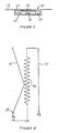
- input panel 21 includes an elongated elastic sheet 27 on which a plurality of cooking condition set key-patterns 29 are formed.
- the cooking condition key-patterns are arranged at prescribed intervals along the elongated direction of sheet 27.
- Cooking condition key-patterns 29 include cooking mode keys, a cooking start key, etc.
- Elastic elongated sheet 27 is provided with an elongated hollow portion 31 therein.
- a flexible electric conductive layer 33 is provided, in the elongated direction of sheet 27, on the one surface of hollow portion 31 corresponding to the front surface of sheet 27.
- the cooking condition set key-patterns 29 are formed thereon, as shown in FIGURE 3.
- Conductive layer 33 is formed in an arc-shape.
- An elongated plate-shaped resistor 35 is provided on the other surface of hollow portion 31 opposite to conductive layer 33.
- a conductive lead pattern 37 also is provided in elongated sheet 27 in parallel to plate-shaped resistor 35, as shown in FIGURES 2 and 3.
- One end of plate-shaped resistor 35 is connected to lead pattern 37, and the other end thereof is grounded for applying DC voltage +V to resistor 35 through lead pattern 37.
- a terminal 39 is connected to one side of conductive layer 33.
- Input panel 21 with the above-described construction is arranged on operation panel 19 such that the front surface of elastic sheet 27 is flush with operation panel 19.
- FIGURE 5 is a control block diagram of the above- described oven.
- Key-signal data from input panel 21 is input to a control section 41 through an A/D (analog/digital) converter 43.
- Control section 41 includes a microcomputer and its peripheral control unit. Cooking time data set by timer knob 25 is input from a mechanical timer 45 to control section 41.
- Control section 41 controls display 23 for displaying the desired cooking mode or other cooking information.
- Control section 41 also controls a heating control circuit 47 for controlling output of a magnetron (not shown) in accordance with those input data.
- the corresponding digital signal (Sa, Sb, Sc, ...., or Sz) is generated from A/D converter 43.
- the relationship between each cooking condition key-pattern and the corresponding digital signal (hereinafter referred to as KEY TABLE) is previously stored in a ROM (read only memory) in control section 41.
- A/D converter 43 outputs the digital signal corresponding to the voltage Vo produced from input panel 21.
- the microcomputer of control section 41 receives the digital signal, as described above. According to the digital signal, the microcomputer reads out the desired cooking mode from the ROM in which the KEY TABLE is stored. For example, the desired cooking mode is displayed in display 23. In accordance with the cooking mode read out from the ROM, the microcomputer energizes the magnetron through heating control circuit 47.
- input panel 21 comprises elongated flexible conductive layer 33 and elongated plate-shaped resistor 35 opposite to one another.
- the voltage Vo between layer 33 and resistor 35 varies in accordance with the position at which conductive layer 33 contacts with resistor 35 when a desired cooking condition set key-pattern is pressed.
- A/D converter 43 Based on the voltage Vo from input panel 21, A/D converter 43 generates the corresponding digital signal. Therefore, since a large number of signal lines of the above-described prior art are eliminated, the construction of the inut panel may be simplified. In addition, the manufacturing cost of an input panel may be reduced.
- FIGURE 7 is a schematic view illustrating a second embodiment of the present invention.
- a plurality of cooking condition set key-patterns are provided on operation panel 19.
- a plurality of press-bar elements 51 corresponding to cooking condition set key-patterns perpendicularly project from the rear surface of operation panel 19 at prescribed intervals.
- the area around each press-bar element 51 of the rear surface of operation panel 19 is concaved toward the front surface thereof to easily reciprocate press-bar element 51.
- Conductive layer 33 is positioned apart therefrom between operation panel 19 and resistor 35.
- FIGURES 8, 9, 10 and 11 show a third embodiment of the present invention.
- the cooking time scale pattern 61 of a cooking timer is provided on elastic sheet 27, instead of mechanical timer 45 shown in FIGURE 5.
- A/D converter 43 provides a digital signal (St1,----------, or St60) representing the desired cooking time to control section 41 after receiving the voltage Vo from input panel 21.
- the microcomputer of control section 41 controls the oscillating period of the magnetron through heating control circuit 47 in accordance with the digital signal from A/D converter 43 representing the desired cooking time.
- a temperature scale pattern for inputting desired temperature data may be provided on the input panel. Furthermore, it may use one scale pattern both as a cooking time scale and a temperature scale.
Landscapes
- Engineering & Computer Science (AREA)
- Human Computer Interaction (AREA)
- Physics & Mathematics (AREA)
- Electromagnetism (AREA)
- Theoretical Computer Science (AREA)
- Electric Ovens (AREA)
Applications Claiming Priority (4)
| Application Number | Priority Date | Filing Date | Title |
|---|---|---|---|
| JP14753586A JPS636323A (ja) | 1986-06-24 | 1986-06-24 | 調理器 |
| JP147535/86 | 1986-06-24 | ||
| JP253205/86 | 1986-10-24 | ||
| JP61253205A JPS63108124A (ja) | 1986-10-24 | 1986-10-24 | 調理器 |
Publications (3)
| Publication Number | Publication Date |
|---|---|
| EP0251670A2 true EP0251670A2 (de) | 1988-01-07 |
| EP0251670A3 EP0251670A3 (en) | 1990-02-21 |
| EP0251670B1 EP0251670B1 (de) | 1994-05-04 |
Family
ID=26478039
Family Applications (1)
| Application Number | Title | Priority Date | Filing Date |
|---|---|---|---|
| EP87305608A Expired - Lifetime EP0251670B1 (de) | 1986-06-24 | 1987-06-24 | Kontrollvorrichtung für Kochgeräte |
Country Status (4)
| Country | Link |
|---|---|
| US (1) | US4920253A (de) |
| EP (1) | EP0251670B1 (de) |
| CA (1) | CA1287117C (de) |
| DE (1) | DE3789732T2 (de) |
Families Citing this family (4)
| Publication number | Priority date | Publication date | Assignee | Title |
|---|---|---|---|---|
| JP2604032B2 (ja) * | 1989-04-27 | 1997-04-23 | 株式会社東芝 | 電気加熱調理器 |
| US5138137A (en) * | 1990-12-27 | 1992-08-11 | Whirlpool Corporation | Fault detecting membrane potentiometer switch |
| US5690093A (en) * | 1995-01-19 | 1997-11-25 | Nutone, Inc. | Ventilator controller with variably adjustable fan and light |
| US6737990B1 (en) * | 1998-01-23 | 2004-05-18 | Spyrus, Inc. | Key input apparatus interface |
Family Cites Families (13)
| Publication number | Priority date | Publication date | Assignee | Title |
|---|---|---|---|---|
| JPS4842962B1 (de) * | 1969-02-20 | 1973-12-15 | ||
| US4145584A (en) * | 1976-04-28 | 1979-03-20 | Otterlei Jon L | Flexible keyboard switch with integral spacer protrusions |
| US4121204A (en) * | 1976-12-14 | 1978-10-17 | General Electric Company | Bar graph type touch switch and display device |
| US4149217A (en) * | 1977-07-26 | 1979-04-10 | Rangaire Corporation | Touch control panel for induction heating cook-top |
| US4221975A (en) * | 1978-04-19 | 1980-09-09 | Touch Activated Switch Arrays, Inc. | Touch activated controller and method |
| US4301337A (en) * | 1980-03-31 | 1981-11-17 | Eventoff Franklin Neal | Dual lateral switch device |
| DE3038102C2 (de) * | 1980-10-09 | 1982-07-15 | Robert Ing.(grad.) 7995 Neukirch Buck | Elektronisches, berührungslos arbeitendes Schaltgerät |
| JPS57137926A (en) * | 1981-02-19 | 1982-08-25 | Sharp Corp | Electric signal input device |
| US4631525A (en) * | 1983-04-11 | 1986-12-23 | Sony Corporation | Digital fader or like device |
| EP0136630A3 (de) * | 1983-10-03 | 1986-10-08 | Siemens Aktiengesellschaft | Alphanumerisches Tastenfeld |
| JPS60148019A (ja) * | 1983-12-22 | 1985-08-05 | アンプ インコーポレーテツド | 膜スイツチ組立体 |
| US4594482A (en) * | 1984-01-23 | 1986-06-10 | Canon Kabushiki Kaisha | Input element with improved appearance and reliability |
| US4737656A (en) * | 1986-04-02 | 1988-04-12 | Izumi Corporation Industries, Inc. | Multiple switch control system |
-
1987
- 1987-06-23 CA CA000540311A patent/CA1287117C/en not_active Expired - Lifetime
- 1987-06-24 DE DE3789732T patent/DE3789732T2/de not_active Expired - Fee Related
- 1987-06-24 EP EP87305608A patent/EP0251670B1/de not_active Expired - Lifetime
-
1989
- 1989-01-05 US US07/293,611 patent/US4920253A/en not_active Expired - Fee Related
Also Published As
| Publication number | Publication date |
|---|---|
| DE3789732T2 (de) | 1994-08-18 |
| US4920253A (en) | 1990-04-24 |
| DE3789732D1 (de) | 1994-06-09 |
| CA1287117C (en) | 1991-07-30 |
| EP0251670A3 (en) | 1990-02-21 |
| EP0251670B1 (de) | 1994-05-04 |
Similar Documents
| Publication | Publication Date | Title |
|---|---|---|
| US6097016A (en) | Cooking apparatus having display unit and item selection unit | |
| US4621178A (en) | Microwave oven having a keyboard of the membrane type | |
| US4566001A (en) | Touch strip input for display terminal | |
| EP0264884B2 (de) | Eingangsvorrichtung mit Tasten | |
| WO1992009994A1 (en) | Glass membrane touch-controlled circuit apparatus for voltage selection | |
| GB2155211A (en) | Cooking apparatus | |
| EP0251670A2 (de) | Kontrollvorrichtung für Kochgeräte | |
| CA1162247A (en) | A heating apparatus with a digit change-over switch | |
| JPH0653015A (ja) | ワンタッチ式アナログ情報入力装置および該装置に用いる可変抵抗器 | |
| JP3107210B2 (ja) | 高周波加熱装置 | |
| KR920008926B1 (ko) | 조리기 | |
| JPS6131371B2 (de) | ||
| JPS636323A (ja) | 調理器 | |
| JPH0625959B2 (ja) | 入力装置 | |
| JPH0673254B2 (ja) | キ−入力装置 | |
| JPH0673255B2 (ja) | キ−入力装置 | |
| JPS58178126A (ja) | パネル操作形電子レンジ | |
| JPH01253788A (ja) | 画像パターン入出力装置 | |
| JPS5620933A (en) | High-frequency heating apparatus | |
| KR19990058196A (ko) | 전자렌지용 멤브레인 키보드와 그 제어방법 | |
| KR940001762B1 (ko) | 전자레인지의 키이입력방법 | |
| JPH0141913B2 (de) | ||
| JPS62190694A (ja) | 調理器 | |
| JPS6023724A (ja) | 調理器 | |
| JPH0757585A (ja) | 加熱調理器 |
Legal Events
| Date | Code | Title | Description |
|---|---|---|---|
| PUAI | Public reference made under article 153(3) epc to a published international application that has entered the european phase |
Free format text: ORIGINAL CODE: 0009012 |
|
| 17P | Request for examination filed |
Effective date: 19870710 |
|
| AK | Designated contracting states |
Kind code of ref document: A2 Designated state(s): DE FR GB |
|
| PUAL | Search report despatched |
Free format text: ORIGINAL CODE: 0009013 |
|
| AK | Designated contracting states |
Kind code of ref document: A3 Designated state(s): DE FR GB |
|
| 17Q | First examination report despatched |
Effective date: 19920416 |
|
| GRAA | (expected) grant |
Free format text: ORIGINAL CODE: 0009210 |
|
| AK | Designated contracting states |
Kind code of ref document: B1 Designated state(s): DE FR GB |
|
| REF | Corresponds to: |
Ref document number: 3789732 Country of ref document: DE Date of ref document: 19940609 |
|
| ET | Fr: translation filed | ||
| PLBE | No opposition filed within time limit |
Free format text: ORIGINAL CODE: 0009261 |
|
| STAA | Information on the status of an ep patent application or granted ep patent |
Free format text: STATUS: NO OPPOSITION FILED WITHIN TIME LIMIT |
|
| 26N | No opposition filed | ||
| PGFP | Annual fee paid to national office [announced via postgrant information from national office to epo] |
Ref country code: FR Payment date: 19950609 Year of fee payment: 9 |
|
| PGFP | Annual fee paid to national office [announced via postgrant information from national office to epo] |
Ref country code: GB Payment date: 19950613 Year of fee payment: 9 |
|
| PGFP | Annual fee paid to national office [announced via postgrant information from national office to epo] |
Ref country code: DE Payment date: 19950617 Year of fee payment: 9 |
|
| PG25 | Lapsed in a contracting state [announced via postgrant information from national office to epo] |
Ref country code: GB Effective date: 19960624 |
|
| GBPC | Gb: european patent ceased through non-payment of renewal fee |
Effective date: 19960624 |
|
| PG25 | Lapsed in a contracting state [announced via postgrant information from national office to epo] |
Ref country code: FR Effective date: 19970228 |
|
| PG25 | Lapsed in a contracting state [announced via postgrant information from national office to epo] |
Ref country code: DE Effective date: 19970301 |
|
| REG | Reference to a national code |
Ref country code: FR Ref legal event code: ST |