EP0252593B1 - Geräuscharmer Tintenstrahldüsenzusammenbau - Google Patents
Geräuscharmer Tintenstrahldüsenzusammenbau Download PDFInfo
- Publication number
- EP0252593B1 EP0252593B1 EP87304465A EP87304465A EP0252593B1 EP 0252593 B1 EP0252593 B1 EP 0252593B1 EP 87304465 A EP87304465 A EP 87304465A EP 87304465 A EP87304465 A EP 87304465A EP 0252593 B1 EP0252593 B1 EP 0252593B1
- Authority
- EP
- European Patent Office
- Prior art keywords
- nozzle
- ink
- energy
- khz
- disturbing energy
- Prior art date
- Legal status (The legal status is an assumption and is not a legal conclusion. Google has not performed a legal analysis and makes no representation as to the accuracy of the status listed.)
- Expired - Lifetime
Links
- 239000004734 Polyphenylene sulfide Substances 0.000 claims abstract description 10
- 229920000069 polyphenylene sulfide Polymers 0.000 claims abstract description 10
- 239000002904 solvent Substances 0.000 claims description 7
- 230000003321 amplification Effects 0.000 claims description 5
- 238000003199 nucleic acid amplification method Methods 0.000 claims description 5
- 238000009877 rendering Methods 0.000 claims description 4
- 238000000034 method Methods 0.000 claims description 3
- 230000005540 biological transmission Effects 0.000 claims description 2
- 239000012530 fluid Substances 0.000 abstract description 22
- 239000000463 material Substances 0.000 abstract description 22
- 230000002238 attenuated effect Effects 0.000 abstract 1
- 239000000976 ink Substances 0.000 description 43
- 238000012360 testing method Methods 0.000 description 13
- 230000015572 biosynthetic process Effects 0.000 description 8
- 239000007779 soft material Substances 0.000 description 8
- DHKHKXVYLBGOIT-UHFFFAOYSA-N acetaldehyde Diethyl Acetal Natural products CCOC(C)OCC DHKHKXVYLBGOIT-UHFFFAOYSA-N 0.000 description 6
- 239000010437 gem Substances 0.000 description 6
- 229910001751 gemstone Inorganic materials 0.000 description 6
- 125000002777 acetyl group Chemical class [H]C([H])([H])C(*)=O 0.000 description 4
- 229920001519 homopolymer Polymers 0.000 description 4
- 238000004519 manufacturing process Methods 0.000 description 4
- 229920004943 Delrin® Polymers 0.000 description 3
- 230000000712 assembly Effects 0.000 description 3
- 238000000429 assembly Methods 0.000 description 3
- 230000008878 coupling Effects 0.000 description 3
- 238000010168 coupling process Methods 0.000 description 3
- 238000005859 coupling reaction Methods 0.000 description 3
- 239000002184 metal Substances 0.000 description 3
- 239000000758 substrate Substances 0.000 description 3
- 239000004743 Polypropylene Substances 0.000 description 2
- 239000000853 adhesive Substances 0.000 description 2
- 238000004026 adhesive bonding Methods 0.000 description 2
- 230000001070 adhesive effect Effects 0.000 description 2
- 239000011230 binding agent Substances 0.000 description 2
- 239000007767 bonding agent Substances 0.000 description 2
- 229920001577 copolymer Polymers 0.000 description 2
- 239000011521 glass Substances 0.000 description 2
- 238000007641 inkjet printing Methods 0.000 description 2
- 230000007774 longterm Effects 0.000 description 2
- 230000010355 oscillation Effects 0.000 description 2
- 239000004033 plastic Substances 0.000 description 2
- -1 polypropylene Polymers 0.000 description 2
- 229920001155 polypropylene Polymers 0.000 description 2
- 239000004593 Epoxy Substances 0.000 description 1
- 239000004721 Polyphenylene oxide Substances 0.000 description 1
- 150000001298 alcohols Chemical class 0.000 description 1
- 238000004458 analytical method Methods 0.000 description 1
- 235000013361 beverage Nutrition 0.000 description 1
- 150000001875 compounds Chemical class 0.000 description 1
- 239000004020 conductor Substances 0.000 description 1
- 239000013078 crystal Substances 0.000 description 1
- 230000001419 dependent effect Effects 0.000 description 1
- 125000003700 epoxy group Chemical group 0.000 description 1
- 238000001704 evaporation Methods 0.000 description 1
- 230000008020 evaporation Effects 0.000 description 1
- 238000002955 isolation Methods 0.000 description 1
- 150000002576 ketones Chemical class 0.000 description 1
- 230000014759 maintenance of location Effects 0.000 description 1
- 239000000203 mixture Substances 0.000 description 1
- 238000000465 moulding Methods 0.000 description 1
- 229920000647 polyepoxide Polymers 0.000 description 1
- 229920006380 polyphenylene oxide Polymers 0.000 description 1
- 230000002028 premature Effects 0.000 description 1
- 238000007639 printing Methods 0.000 description 1
- XLYOFNOQVPJJNP-UHFFFAOYSA-N water Substances O XLYOFNOQVPJJNP-UHFFFAOYSA-N 0.000 description 1
Images


Classifications
-
- B—PERFORMING OPERATIONS; TRANSPORTING
- B41—PRINTING; LINING MACHINES; TYPEWRITERS; STAMPS
- B41J—TYPEWRITERS; SELECTIVE PRINTING MECHANISMS, i.e. MECHANISMS PRINTING OTHERWISE THAN FROM A FORME; CORRECTION OF TYPOGRAPHICAL ERRORS
- B41J29/00—Details of, or accessories for, typewriters or selective printing mechanisms not otherwise provided for
- B41J29/10—Sound-deadening devices embodied in machines
-
- B—PERFORMING OPERATIONS; TRANSPORTING
- B41—PRINTING; LINING MACHINES; TYPEWRITERS; STAMPS
- B41J—TYPEWRITERS; SELECTIVE PRINTING MECHANISMS, i.e. MECHANISMS PRINTING OTHERWISE THAN FROM A FORME; CORRECTION OF TYPOGRAPHICAL ERRORS
- B41J2/00—Typewriters or selective printing mechanisms characterised by the printing or marking process for which they are designed
- B41J2/005—Typewriters or selective printing mechanisms characterised by the printing or marking process for which they are designed characterised by bringing liquid or particles selectively into contact with a printing material
- B41J2/01—Ink jet
- B41J2/015—Ink jet characterised by the jet generation process
- B41J2/02—Ink jet characterised by the jet generation process generating a continuous ink jet
- B41J2/025—Ink jet characterised by the jet generation process generating a continuous ink jet by vibration
Definitions
- This invention relates to drop marking equipment and, in particular, to nozzles used in such drop marking equipment or ink jet devices.
- Such devices employ inks which are supplied from a reservoir to a nozzle.
- the nozzle directs ink at a substrate to be marked.
- electrical energy is converted into mechanical energy, which is coupled to the ink in the nozzle.
- the stream of ink ejected from an orifice at one end of the nozzle is broken up into a series of regularly spaced, discrete droplets which may be selectively given an electrical charge.
- those drops which receive a charge are deflected onto a substrate while those which are not charged are recovered and returned to the ink supply.
- the transducer applies an impulse of energy to the fluid in the nozzle each instance that a droplet is needed.
- ink jet nozzles contribute to cost and speed limitations. For example, it is often desirable to group together several such nozzles to permit high speed printing on a substrate which may be, for example, magazines, envelopes, labels, beverage cans on other products moving on a conveyor. It is not uncommon for ink jet nozzles in some applications to be spaced as closely as six per inch and thus the need for a low cost, high quality, miniaturized device is apparent.
- ink jet nozzles A significant contributing factor to the complexity and cost of producing ink jet nozzles is the presence of both fluid and mechanical resonances in such assemblies which interfere with the nozzle's usefulness over the range of frequencies usually employed to form the ink droplets. Typical useful frequencies range from 10 KHz to 100 KHz. Such resonances vary with the type of ink employed, temperature, and the geometric dimensions of the nozzle assembly. They are also significantly affected by the type of material used to manufacture the nozzle. As a result ink jet printers have required a variety of different nozzles to permit operation at different frequencies and for different kinds of inks.
- ink jet nozzle assemblies have been manufactured from metal or glass materials and are acoustically "hard” meaning that they suffer from the presence of both fluid and mechanical resonances over the range of frequencies employed by the transducer to form the ink drops.
- the present invention is concerned therefore, with providing nozzles without resonance so as to eliminate the antiresonance regions in the operating frequency range and thereby extend the operating frequency range of the nozzle.
- acoustically soft materials were sought so that resonances would be substantially unsupported. This permits only the disturbing energy created by an electromechanical transducer, for example, a piezoelectric crystal, operating at a selected frequency to be transmitted to the fluid.
- a nozzle formed of acetal homopolymer encounters significant antiresonances within the ranges 10 to 20 KHz and 70 to 90 KHz which cause undesirable increases in the drive voltages and it is an object of this invention to provide an acoustically soft nozzle which obviates or mitigates such undesirable drive voltage increase.
- a nozzle for use with a transducer which provides disturbing energy to an ink stream passing through the nozzle to form ink droplets.
- the nozzle comprises a tubular member having an orifice at one end, with its other end being adapted for connection to a supply of ink containing solvents.
- the nozzle is moulded from polyphenylene sulfide, thus rendering it acoustically soft.
- the response of the nozzle to the disturbing energy of the transducer over a frequency in the range of 10 KHz to 100 KHz is substantially flat, the disturbing energy being transmitted to the ink within the nozzle without substantial amplification, attenuation or the creation of harmonic resonances of a frequency characterizing the disturbing energy.
- Figure 1 is a cross sectional view of a nozzle assembly according to a preferred embodiment of the present invention.
- Figure 2 is an enlarge sectional view of the nozzle and tail piece according to the preferred embodiment.
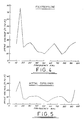
- Figure 3 through 9 are similar curves illustrating the response characteristics for a number of different material tested as to their suitability for use in the present invention.
- the present invention relates to a nozzle assembly for ink jet printing which has significant advantages over presently known assemblies which are typically machined from metal, glass or other acoustically "hard” materials, or formed of an unsatisfactory acoustically soft material (see US-A-4319251).
- Typical useful frequencies range from 10 KHz to 100 KHz.
- Typical inks suitable for use in ink jet printers have the following range of characteristics:
- the velocity of sound in the ink is of significant concern in the design of nozzles.
- the velocity of sound in such a fluid varies with the temperature of the fluid and, therefore, the fluid resonances (related to the velocity of sound) change frequency as a function of temperature changes in the nozzle.
- the resonances may be different during initial operation, when the nozzle is cool, than after the nozzle has been in use for a period of time.
- the velocity of sound is affected by changes in the composition of the ink due mainly to evaporation of solvents.
- a nozzle assembly which is acoustically soft.
- the nozzle may need to be extremely small to work in some applications, subjected to continual temperature changes and vibration and, most importantly, is in contact with different inks containing water or various alcohols, ketones and other solvents. It is necessary, therefore,to select materials which can stand up to this environment in addition to being acoustically soft.
- acetal homopolymers such as Delrin, acetal copolymers, polypropylene, polyphenylene sulfide, polyphenylene oxide.
- nozzle bodies were designed, molded and tested.
- FIG. 2 illustrates the nozzle assembly molded from the various materials for purposes of testing.
- a nozzle 30 is an elongated, hollow cylindrical member. At one end thereof is a female coupling 32 adapted to receive a tail piece 34 having a male coupling member 36. The tail piece 34, in turn, can be coupled to a conduit member for providing an ink supply to the nozzle 30.
- the distal end of the nozzle 30 has a recessed portion 37 adapted to receive and retain an orifice jewel 38 therein. Retention is accomplished by dimensioning the recess to provide an interference fit which firmly seats the jewel and prevents leakage. It was found that an interference fit of approximately 0.0038cm (0.0015 inch) was adequate to retain the jewel in place with a recess depth of approximately two times the thickness of the jewel. With such dimensions the nozzle material closes around the jewel to retain it securely in place.
- a piezoelectric transducer was coupled by adhesive bonding.
- the bonding agent was selected to insure a good coupling between the piezoelectric device and the nozzle for transmission of energy to the fluid.
- Epoxies are preferred and, in particular, a one part binder which is not too viscous is best. This permits the binder to flow well in the space between the nozzle and the piezo electric device to avoid gaps which can cause undesirable variations in the applied energy, require higher drive voltages, contribute to mechanical resonance and lead to premature failure of the device.
- the bonding material is relatively stiff to maintain drive efficiency.
- One suitable adhesive bonding agent is an anaerobic adhesive sold under the trade name Permalok by Permabond International Corporation, Englewood, New Jersey.
- Figure 4 shows the test data for polypropylene. It has a variety of antiresonance throughout the frequency range of interest and is therefore not suitable for present purposes.
- Figure 5 illustrates the test data for the acetal copolymer which has undesirable antiresonances at 10 to 20 KHz and above 90 KHz.
- Figure 6 illustrates that data for polyphenylene sulfide (two tests are shown, one in which the nozzle is potted in a block, the other unpotted).
- the material is much better than the prior art metal nozzles and significantly better than any of the other acoustically soft materials tested.
- Its response characteristic is essentially flat from 10KHz to 100KHz. This indicates, particularly in view of the low drive voltage required to maintain constant droplet production, that the material very efficiently couples the piezoelectric device and the fluid while at the same time being acoustically soft to not support fluid resonance. Because it is a molded part and is directly coupled to the driving device by an adhesive, there is little mechanical resonance created.
- This material was designated as the preferred material for the production of a new, highly efficient nozzle assembly for ink jet printing. Such a nozzle can be driven at a substantially uniform voltage over the desired operating range of frequencies.
- a nozzle 50 formed of polyphenylene sulfide is coupled to a tail piece 52 preferably formed of the same materials.
- the tail piece is coupled to a fitting 54 for connection to an ink supply conduit.
- a jewel 56 is provided in the forward portion of the nozzle and captured therein by virtue of the dimensions of the nozzle recess as previously described.
- Concentrically mounted over the nozzle 50 is a piezoelectric transducer 58 adhesively bonded in place. The devices are electrically driven by means of a cable 61, the conductors contained therein being soldered to the outside of the transducers as indicated.
- the nozzle assembly is preferably potted and disposed within a nozzle head assembly or block 60.
- the completed assembly is small enough to permit spacing in the order of six separate print heads per 2.54 cm (per inch).
- the nozzles according to the present invention have good, long term resistance to ink solvents, are relatively temperature insensitive, and can be driven at substantially uniform drive voltages over a wide range of operating frequencies.
- the fluid does not "experience" a rigid confining wall and does not form standing waves which generate fluid resonances within the nozzle body.
- the antiresonances representing sharp increases in the acoustic impedance of the ink are also eliminated.
- droplet formation is accomplished across a broad frequency range by a substantially uniform driving voltage.
- an independently controlled potential may be applied to the ink permitting, for example, increased deflection by the techniques taught in US-A- 4,319,251.
- phasing of drop formation and drop charging is facilitated by permitting charging currents in the ink to be reliably detected.
- ink confined to the chamber in either instance, and forming the wall or walls of the nozzle ink chamber of acoustically soft material in accordance with the teachings of the present invention assures that the disturbing energy coupled to the chamber is transmitted to the ink within the chamber without substantial amplification, attenuation or the creation of harmonic resonances of any frequency characterizing the disturbing energy.
- the present invention is useful also in ink jet printers that employ a pulsed nozzle to form droplets.
- Zolton U.S. Patent 3,683,212 discloses one example of that type of nozzle.
- the impulses of electrical energy used to drive such a nozzle commonly have a duration of 10 microseconds to 100 microseconds.
- a Fourier analysis of those energy pulses manifests that reliable droplet formation necessitates that the nozzle respond consistently to frequencies in the range of 10KHz to 100KHz. It is desirable that the nozzle chamber not support fluid resonances in that frequency range.
- a nozzle which has a fluid chamber with walls made of acoustically soft material as taught by the present invention will not support resonances in that region, and thus will have a substantially flat response to energy impulses characterized by frequencies that are within the operating frequency range.
- droplet formation is more nearly proportional to the characteristics of the energy pulse applied to the fluid to improve control and enhance the marking results.
- spurious oscillations in the impulse nozzle ink chamber that occur after a pulse has directed formation of a droplet are absorbed if the walls are made of acoustically soft material. Those spurious oscillations can distort the energy applied to the fluid when a succeeding command pulse is transmitted to the fluid.
- an impulse or pulse driven nozzle can be operated more advantageously by following the teachings of the present invention.
Landscapes
- Particle Formation And Scattering Control In Inkjet Printers (AREA)
Claims (4)
Priority Applications (1)
| Application Number | Priority Date | Filing Date | Title |
|---|---|---|---|
| AT87304465T ATE73051T1 (de) | 1986-07-09 | 1987-05-20 | Geraeuscharmer tintenstrahlduesenzusammenbau. |
Applications Claiming Priority (2)
| Application Number | Priority Date | Filing Date | Title |
|---|---|---|---|
| US06/883,707 US4727379A (en) | 1986-07-09 | 1986-07-09 | Accoustically soft ink jet nozzle assembly |
| US883707 | 1986-07-09 |
Publications (3)
| Publication Number | Publication Date |
|---|---|
| EP0252593A2 EP0252593A2 (de) | 1988-01-13 |
| EP0252593A3 EP0252593A3 (en) | 1989-06-07 |
| EP0252593B1 true EP0252593B1 (de) | 1992-03-04 |
Family
ID=25383169
Family Applications (1)
| Application Number | Title | Priority Date | Filing Date |
|---|---|---|---|
| EP87304465A Expired - Lifetime EP0252593B1 (de) | 1986-07-09 | 1987-05-20 | Geräuscharmer Tintenstrahldüsenzusammenbau |
Country Status (9)
| Country | Link |
|---|---|
| US (1) | US4727379A (de) |
| EP (1) | EP0252593B1 (de) |
| JP (1) | JPH0655504B2 (de) |
| AT (1) | ATE73051T1 (de) |
| AU (1) | AU587336B2 (de) |
| CA (1) | CA1286912C (de) |
| DE (1) | DE3776992D1 (de) |
| MX (1) | MX171176B (de) |
| ZA (1) | ZA873541B (de) |
Families Citing this family (14)
| Publication number | Priority date | Publication date | Assignee | Title |
|---|---|---|---|---|
| KR0165677B1 (ko) * | 1989-01-20 | 1999-05-01 | 요하네스 야코부스 스모렌버그 | 잉크-제트 방식 인쇄기용 노즐 |
| US5196860A (en) * | 1989-03-31 | 1993-03-23 | Videojet Systems International, Inc. | Ink jet droplet frequency drive control system |
| WO1990014956A1 (fr) * | 1989-05-29 | 1990-12-13 | Leningradsky Institut Tochnoi Mekhaniki I Optiki | Generateur electrique de jet de gouttelettes et son procede de reglage |
| US5063393A (en) * | 1991-02-26 | 1991-11-05 | Videojet Systems International, Inc. | Ink jet nozzle with dual fluid resonances |
| US5901425A (en) | 1996-08-27 | 1999-05-11 | Topaz Technologies Inc. | Inkjet print head apparatus |
| US6070973A (en) * | 1997-05-15 | 2000-06-06 | Massachusetts Institute Of Technology | Non-resonant and decoupled droplet generator |
| IL127484A (en) * | 1998-12-09 | 2001-06-14 | Aprion Digital Ltd | Laser container printing method and method |
| EP1080915B1 (de) | 1999-09-03 | 2011-07-20 | Canon Kabushiki Kaisha | Flüssigkeitausstosskopfeinheit |
| US6675914B2 (en) * | 2002-02-19 | 2004-01-13 | Halliburton Energy Services, Inc. | Pressure reading tool |
| US7077334B2 (en) * | 2003-04-10 | 2006-07-18 | Massachusetts Institute Of Technology | Positive pressure drop-on-demand printing |
| EP1637329A1 (de) | 2004-09-15 | 2006-03-22 | Domino Printing Sciences Plc | Tröpfchengenerator |
| US20080191066A1 (en) * | 2007-02-13 | 2008-08-14 | Ted Jernigan | Water cutting assembly and nozzle nut |
| GB0719374D0 (en) * | 2007-10-04 | 2007-11-14 | Eastman Kodak Co | Continuous inkjet printing |
| FR3088242A1 (fr) | 2018-11-14 | 2020-05-15 | Dover Europe Sarl | Procede et dispositif de formation de gouttes a l'aide d'une cavite a facteur de qualite degrade |
Family Cites Families (23)
| Publication number | Priority date | Publication date | Assignee | Title |
|---|---|---|---|---|
| US3334350A (en) * | 1964-08-19 | 1967-08-01 | Dick Co Ab | Magnetostrictive ink jet |
| US3281859A (en) * | 1964-08-20 | 1966-10-25 | Dick Co Ab | Apparatus for forming drops |
| US3281860A (en) * | 1964-11-09 | 1966-10-25 | Dick Co Ab | Ink jet nozzle |
| US3512172A (en) * | 1968-08-22 | 1970-05-12 | Dick Co Ab | Ink drop writer nozzle |
| US3946398A (en) * | 1970-06-29 | 1976-03-23 | Silonics, Inc. | Method and apparatus for recording with writing fluids and drop projection means therefor |
| US3683396A (en) * | 1970-08-05 | 1972-08-08 | Dick Co Ab | Method and apparatus for control of ink drop formation |
| US3683212A (en) * | 1970-09-09 | 1972-08-08 | Clevite Corp | Pulsed droplet ejecting system |
| US3708118A (en) * | 1971-04-19 | 1973-01-02 | Dick Co Ab | Filtering apparatus for a drop writing system |
| US3736593A (en) * | 1971-10-12 | 1973-05-29 | Dick Co Ab | Ink drop writing system with nozzle drive frequency control |
| US3832579A (en) * | 1973-02-07 | 1974-08-27 | Gould Inc | Pulsed droplet ejecting system |
| US3850717A (en) * | 1973-12-03 | 1974-11-26 | Dick Co Ab | Prestressing and damping of piezo ceramic type nozzles |
| US3972474A (en) * | 1974-11-01 | 1976-08-03 | A. B. Dick Company | Miniature ink jet nozzle |
| JPS5928471B2 (ja) * | 1976-12-17 | 1984-07-13 | シャープ株式会社 | 液体ジエツト供給機構 |
| US4153901A (en) * | 1976-12-20 | 1979-05-08 | Recognition Equipment Incorporated | Variable frequency multi-orifice IJP |
| US4201995A (en) * | 1978-12-04 | 1980-05-06 | Xerox Corporation | Coincidence gate ink jet with increased operating pressure window |
| US4248823A (en) * | 1978-12-15 | 1981-02-03 | Ncr Corporation | Method of making ink jet print head |
| JPS594310B2 (ja) * | 1979-06-30 | 1984-01-28 | 株式会社リコー | インクジェット記録装置 |
| US4257052A (en) * | 1979-10-29 | 1981-03-17 | The Mead Corporation | Molded orifice plate assembly for an ink jet recorder and method of manufacture |
| JPS5727761A (en) * | 1980-07-29 | 1982-02-15 | Hitachi Ltd | Nozzle for ink jet recording device |
| US4319251A (en) * | 1980-08-15 | 1982-03-09 | A. B. Dick Company | Ink jet printing employing reverse charge coupling |
| US4349830A (en) * | 1980-11-12 | 1982-09-14 | Burroughs Corporation | Conical nozzle for an electrostatic ink jet printer |
| US4395719A (en) * | 1981-01-05 | 1983-07-26 | Exxon Research And Engineering Co. | Ink jet apparatus with a flexible piezoelectric member and method of operating same |
| US4376944A (en) * | 1981-04-13 | 1983-03-15 | Ncr Corporation | Ink jet print head with tilting nozzle |
-
1986
- 1986-07-09 US US06/883,707 patent/US4727379A/en not_active Ceased
-
1987
- 1987-05-18 ZA ZA873541A patent/ZA873541B/xx unknown
- 1987-05-20 DE DE8787304465T patent/DE3776992D1/de not_active Expired - Fee Related
- 1987-05-20 AT AT87304465T patent/ATE73051T1/de not_active IP Right Cessation
- 1987-05-20 EP EP87304465A patent/EP0252593B1/de not_active Expired - Lifetime
- 1987-05-29 MX MX006716A patent/MX171176B/es unknown
- 1987-06-10 CA CA000539291A patent/CA1286912C/en not_active Expired - Fee Related
- 1987-07-06 AU AU75254/87A patent/AU587336B2/en not_active Expired
- 1987-07-08 JP JP62168907A patent/JPH0655504B2/ja not_active Expired - Lifetime
Also Published As
| Publication number | Publication date |
|---|---|
| ZA873541B (en) | 1987-11-11 |
| JPS6325050A (ja) | 1988-02-02 |
| EP0252593A2 (de) | 1988-01-13 |
| MX171176B (es) | 1993-10-06 |
| AU7525487A (en) | 1988-01-14 |
| EP0252593A3 (en) | 1989-06-07 |
| JPH0655504B2 (ja) | 1994-07-27 |
| AU587336B2 (en) | 1989-08-10 |
| US4727379A (en) | 1988-02-23 |
| CA1286912C (en) | 1991-07-30 |
| ATE73051T1 (de) | 1992-03-15 |
| DE3776992D1 (de) | 1992-04-09 |
Similar Documents
| Publication | Publication Date | Title |
|---|---|---|
| CA1174516A (en) | Ink jet construction and method of construction | |
| US4727379A (en) | Accoustically soft ink jet nozzle assembly | |
| EP0548984B1 (de) | Steuerschaltung für Tintenstrahlaufzeichnungskopf | |
| US3857049A (en) | Pulsed droplet ejecting system | |
| CA1146211A (en) | Hydrodynamically damped pressure pulse droplet ejector | |
| US4032928A (en) | Wideband ink jet modulator | |
| EP1620269B1 (de) | Bildreproduzier-/-erzeugungsvorrichtung mit unter verbesserter steuerungswellenform betriebenem druckkopf | |
| US3902083A (en) | Pulsed droplet ejecting system | |
| GB2050949A (en) | Pulsed liquid droplet ejecting apparatus | |
| EP0095911A2 (de) | Mittels Druckimpulsen arbeitendes Tröpfchenausstosssystem und Anordnung | |
| US4400705A (en) | Ink jet printing apparatus | |
| JPS61154948A (ja) | 液滴供給装置 | |
| US4387383A (en) | Multiple nozzle ink jet print head | |
| GB2088287A (en) | Ink jet printing head | |
| US5854645A (en) | Inkjet array | |
| EP0214855B1 (de) | Auf Abruf arbeitendes Tintenstrahldruckgerät | |
| US4180225A (en) | Ink jet recording apparatus | |
| US4625221A (en) | Apparatus for ejecting droplets of ink | |
| USRE35737E (en) | Accoustically soft ink jet nozzle assembly | |
| US4326206A (en) | Method of reducing cross talk in ink jet arrays | |
| CA1039791A (en) | Nozzle for an ink jet printer | |
| US4065774A (en) | Hybrid fluid jet drop generation | |
| JPS62174163A (ja) | ドロツプオンデマンドインクジエツトヘツド | |
| JP3384200B2 (ja) | インクジェット記録装置およびその駆動方法 | |
| JPS59138472A (ja) | 液体噴射記録ヘッド |
Legal Events
| Date | Code | Title | Description |
|---|---|---|---|
| PUAI | Public reference made under article 153(3) epc to a published international application that has entered the european phase |
Free format text: ORIGINAL CODE: 0009012 |
|
| AK | Designated contracting states |
Kind code of ref document: A2 Designated state(s): AT BE CH DE ES FR GB GR IT LI LU NL SE |
|
| PUAL | Search report despatched |
Free format text: ORIGINAL CODE: 0009013 |
|
| AK | Designated contracting states |
Kind code of ref document: A3 Designated state(s): AT BE CH DE ES FR GB GR IT LI LU NL SE |
|
| 17P | Request for examination filed |
Effective date: 19890726 |
|
| 17Q | First examination report despatched |
Effective date: 19901213 |
|
| GRAA | (expected) grant |
Free format text: ORIGINAL CODE: 0009210 |
|
| AK | Designated contracting states |
Kind code of ref document: B1 Designated state(s): AT BE CH DE ES FR GB GR IT LI LU NL SE |
|
| PG25 | Lapsed in a contracting state [announced via postgrant information from national office to epo] |
Ref country code: SE Effective date: 19920304 Ref country code: NL Effective date: 19920304 Ref country code: LI Effective date: 19920304 Ref country code: GR Free format text: LAPSE BECAUSE OF FAILURE TO SUBMIT A TRANSLATION OF THE DESCRIPTION OR TO PAY THE FEE WITHIN THE PRESCRIBED TIME-LIMIT Effective date: 19920304 Ref country code: CH Effective date: 19920304 Ref country code: BE Effective date: 19920304 Ref country code: AT Effective date: 19920304 |
|
| REF | Corresponds to: |
Ref document number: 73051 Country of ref document: AT Date of ref document: 19920315 Kind code of ref document: T |
|
| ITF | It: translation for a ep patent filed | ||
| REF | Corresponds to: |
Ref document number: 3776992 Country of ref document: DE Date of ref document: 19920409 |
|
| ET | Fr: translation filed | ||
| ITTA | It: last paid annual fee | ||
| PG25 | Lapsed in a contracting state [announced via postgrant information from national office to epo] |
Ref country code: LU Free format text: LAPSE BECAUSE OF NON-PAYMENT OF DUE FEES Effective date: 19920531 |
|
| PG25 | Lapsed in a contracting state [announced via postgrant information from national office to epo] |
Ref country code: ES Free format text: LAPSE BECAUSE OF FAILURE TO SUBMIT A TRANSLATION OF THE DESCRIPTION OR TO PAY THE FEE WITHIN THE PRESCRIBED TIME-LIMIT Effective date: 19920615 |
|
| REG | Reference to a national code |
Ref country code: CH Ref legal event code: PL |
|
| NLV1 | Nl: lapsed or annulled due to failure to fulfill the requirements of art. 29p and 29m of the patents act | ||
| PLBE | No opposition filed within time limit |
Free format text: ORIGINAL CODE: 0009261 |
|
| STAA | Information on the status of an ep patent application or granted ep patent |
Free format text: STATUS: NO OPPOSITION FILED WITHIN TIME LIMIT |
|
| 26N | No opposition filed | ||
| REG | Reference to a national code |
Ref country code: GB Ref legal event code: IF02 |
|
| PGFP | Annual fee paid to national office [announced via postgrant information from national office to epo] |
Ref country code: DE Payment date: 20030529 Year of fee payment: 17 |
|
| PG25 | Lapsed in a contracting state [announced via postgrant information from national office to epo] |
Ref country code: DE Free format text: LAPSE BECAUSE OF NON-PAYMENT OF DUE FEES Effective date: 20041201 |
|
| PG25 | Lapsed in a contracting state [announced via postgrant information from national office to epo] |
Ref country code: IT Free format text: LAPSE BECAUSE OF NON-PAYMENT OF DUE FEES;WARNING: LAPSES OF ITALIAN PATENTS WITH EFFECTIVE DATE BEFORE 2007 MAY HAVE OCCURRED AT ANY TIME BEFORE 2007. THE CORRECT EFFECTIVE DATE MAY BE DIFFERENT FROM THE ONE RECORDED. Effective date: 20050520 |
|
| PGFP | Annual fee paid to national office [announced via postgrant information from national office to epo] |
Ref country code: FR Payment date: 20060515 Year of fee payment: 20 |
|
| PGFP | Annual fee paid to national office [announced via postgrant information from national office to epo] |
Ref country code: GB Payment date: 20060517 Year of fee payment: 20 |
|
| REG | Reference to a national code |
Ref country code: GB Ref legal event code: PE20 |
|
| PG25 | Lapsed in a contracting state [announced via postgrant information from national office to epo] |
Ref country code: GB Free format text: LAPSE BECAUSE OF EXPIRATION OF PROTECTION Effective date: 20070519 |