EP0252889A2 - Verfahren und Anordnung zur Steuerung von Magnetrons - Google Patents
Verfahren und Anordnung zur Steuerung von Magnetrons Download PDFInfo
- Publication number
- EP0252889A2 EP0252889A2 EP87850209A EP87850209A EP0252889A2 EP 0252889 A2 EP0252889 A2 EP 0252889A2 EP 87850209 A EP87850209 A EP 87850209A EP 87850209 A EP87850209 A EP 87850209A EP 0252889 A2 EP0252889 A2 EP 0252889A2
- Authority
- EP
- European Patent Office
- Prior art keywords
- magnetrons
- voltage
- magnetron
- measuring means
- control
- Prior art date
- Legal status (The legal status is an assumption and is not a legal conclusion. Google has not performed a legal analysis and makes no representation as to the accuracy of the status listed.)
- Withdrawn
Links
Images

Classifications
-
- H—ELECTRICITY
- H05—ELECTRIC TECHNIQUES NOT OTHERWISE PROVIDED FOR
- H05B—ELECTRIC HEATING; ELECTRIC LIGHT SOURCES NOT OTHERWISE PROVIDED FOR; CIRCUIT ARRANGEMENTS FOR ELECTRIC LIGHT SOURCES, IN GENERAL
- H05B6/00—Heating by electric, magnetic or electromagnetic fields
- H05B6/64—Heating using microwaves
- H05B6/66—Circuits
- H05B6/68—Circuits for monitoring or control
- H05B6/681—Circuits comprising an inverter, a boost transformer and a magnetron
- H05B6/682—Circuits comprising an inverter, a boost transformer and a magnetron wherein the switching control is based on measurements of electrical values of the circuit
- H05B6/683—Circuits comprising an inverter, a boost transformer and a magnetron wherein the switching control is based on measurements of electrical values of the circuit the measurements being made at the high voltage side of the circuit
-
- H—ELECTRICITY
- H05—ELECTRIC TECHNIQUES NOT OTHERWISE PROVIDED FOR
- H05B—ELECTRIC HEATING; ELECTRIC LIGHT SOURCES NOT OTHERWISE PROVIDED FOR; CIRCUIT ARRANGEMENTS FOR ELECTRIC LIGHT SOURCES, IN GENERAL
- H05B2206/00—Aspects relating to heating by electric, magnetic, or electromagnetic fields covered by group H05B6/00
- H05B2206/04—Heating using microwaves
- H05B2206/044—Microwave heating devices provided with two or more magnetrons or microwave sources of other kind
Definitions
- the present invention relates to a method and to an arrangement for controlling magnetrons in apparatus in which microwave energy is utilized for heating purposes.
- Microwave heating is a technique which can be applied with great advantage in a multiple of processes which include the supply of thermal energy.
- One important advantage in this regard is that the heating power can be controlled in the absence of any inertia.
- microwave equipment is often more expensive than the conventional alternatives.
- the magnetron of such heating equipment is driven by a power unit with associated control system, which constitute the major cost of the equipment. Since the output power of a magnetron is limited, heating equipment will often require the presence of a significant number of magnetrons and associated power units and control systems to achieve a given heating requirement.
- Magnetrons are used almost exclusively as microwave generators for heating purposes. Those properties decisive in this regard are the high efficiency achieved in converting d.c. power to microwave power and the compact geometry of the magnetron.
- One serious drawback is that the voltage required to produce a given power output varies from magnetron to magnetron. This voltage is determined by the internal geometry of the magnetron and the magnetic field strength in the cavity.
- Two types of magnetrons are found, namely those in which the magnetic field is generated by a permanent magnet and those in which the magnetic field is generated by an electromagnet.
- the strength of the permanent magnets varies in manufacture and during operation.
- the magnetron construction includes a magnetic yoke, the permeability of which varies with temperature.
- the operating curve seen as a graph in which the anode voltage is plotted against the anode current, changes together with the geometric changes that take place in the magnetron in response to changes in temperature therein.
- the output power is proportional to the anode current, to a high level of accuracy.
- the fundamental problem resides in the necessity of controlling each magnetron individually, together with the attempt to decrease the number of power units and associ ated control systems.
- the present invention relates to a method for controlling magnetrons with regard to their microwave power, in equipment incorporating a multiple of magnetrons, characterized by connecting two or more magnetrons in parallel with a power unit operative in producing a high voltage for operation of the magnetrons; by connecting to respective magnetrons a separate magnetron regulating circuit which includes measuring means for measuring the anode current through respective magnetrons on the high-voltage side thereof; and galvanically isolating said measuring means from a control circuit, said control circuit being constructed to control the anode current of the magnetron concerned in response to a signal produced by said measuring means.
- the invention relates to an arrangement or system for controlling two or more magnetrons from one and the same power unit, this arrangement having the characteristic features set forth in the following claim 10.
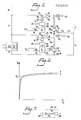
- Figure 6 illustrates an anode voltage - anode current graph which is typical of a magnetron.
- the curve in the graph presents a knee at voltage V0.
- the magnetron will produce no power output at voltages beneath the knee voltage V0.
- the dynamic resistance is low and the voltage increase from no output power to full output power is small.
- the power output of the magnetron is proportional to the anode current I A to a high level of accuracy.
- magnetron there are two types of magnetron, namely magnetrons in which a magnetic field is generated with the aid of permanent magnets, and magnetrons in which the mag netic field is generated by a magnetic coil and a magnetic core.
- the knee voltage is fixed in the former type of magnetron, whereas in the latter type the knee-voltage is controlled or regulated in the manner indicated by the broken-line curve and the arrow in Figure 6, by controlling the current through the winding.
- the present invention relates to a method and to an arrangement or system for controlling a multiple of magnetrons with regard to their microwave power, in which two or more magnetrons are connected in parallel to a power unit effective in generating a high magnetron operating voltage.
- each magnetron is connected to a separate regulating circuit which is individual thereto.
- the regulating curcuit includes a measuring means which is operative in measuring the anode current through the magnetron on the high-voltage side thereof.
- the anode current By measuring the anode current on the high-voltage side of the magnetron, the anode current will be measured individually for each of the magnetrons present while the anode of the magnetron is connected directly to earth, which is highly essential from the aspect of safety.
- the magnetron would be raised at a given potential, which is unacceptable from a safety aspect, assuming that not all of the magnetron is encased in an earthed casing which is insulated from the magnetron, waveguide and possible heating cavity.
- the measuring means is constructed to send a signal to a control circuit. Because the measuring means is located on the high-pressure side, it is galvanically separated from the central circuit, which operates at a relatively low votage, such as normal mains voltage.
- the control circuit is intended to control the anode current of the magnetron, and therewith the power output, in response to the signal received from the measuring means.
- the measuring means comprises a resistance across which the voltage is measured, said voltage constituting the signal sent to the control circuit.
- Figure 1 is a schematic circuit diagram which incorporates two or more magnetrons 1, 2 of the aforesaid kind. These magnetrons are powered from a power unit 3 which is common to all magnetrons and which includes a transformer and a rectifier.
- the power unit 3 may have an output voltage of 3-4 KV for example.
- two magnetrons 1, 2 are connected in parallel across the power unit 3.
- the anodes 4 of the magnetrons 1, 2 are earthed.
- several magnetrons can be connected to the broken-line conductors 5, 6 in the same manner as the two magnetrons 1, 2 and associated circuits connected to the conductors 7, 8.
- a regulating circuit, generally referenced 9, separate for each magnetron is connected to respective magnetrons.
- the regulating circuit 9 incorporates the aforementioned measuring means 10 operative in measuring the anode current through respective conductors 11, 12.
- the measuring means preferably comprises a resistance R across which the voltage is measured through conductors 13, 14; 15, 16.
- the conductors are connected to a measuring circuit 17; 18 of some suitable kind adapted to transfer the measuring value, in the form of said voltage, to a control circuit 19; 20, said value being transferred either in analogue or digital form.
- the measuring means is galvanically separated from the control circuit 19, 20 by means of a circuit 21; 22.
- the circuit may take several different forms. However, a feature common to all forms of this circuit is that the circuit 21; 22 incorporates an analogue-digital converter or a digital-analogue converter, e.g. a frequency-voltage converter, in which the converters are isolated galvanically from one another.
- the circuit 21; 22 includes a voltage-frequency converter 80 which drives a light-emitting device 81, such as a light-emitting diode, such that the light emitter sends light pulses at a pulse repetition frequency corresponding to the voltage applied to the converter 80.
- the circuit 21; 22 also incorporates a frequency-voltage converter 82 to which there is connected a light-sensitive device 83, such as a photo-transistor which receives light transmitted from the light-emitting device 81 and converts this light to electric pulses corresponding to the received light pulses.
- the converter 82 converts the pulses received, e.g., to a voltage that corresponds to the voltage applied across the first mentioned converter.
- the light is suitably passed between the devices 81, 83 in a light conductor 84, such as plastic or glass fibres.
- the aforesaid means for converting a voltage to a frequency may instead be connected to the primary winding of a transformer, the secondary winding of which is connected to means for converting a frequency to a voltage, this latter voltage being delivered to the control circuit 19; 20.
- the control circuit 19, 20 is intended for controlling the anode current of the magnetrons 1, 2 in response to a signal received from the measuring means 10.
- the control means 19, 20 preferably comprises a microprocessor or a corresponding device, into which a control value, or setpoint value, relating to the desired power output is inserted.
- the voltage across the conductors 23, 24; 23, 25 leading to respective power units may also be supplied to the control circuit.
- the control circuit is therewith constructed to calculate the product of this latter voltage and the anode current, this product constituting a relatively acurate measurement of the power output from respective magnetrons.
- the magnetrons have an efficiency of about 70%.
- the anode voltage - anode current diagram of the magnetrons may instead be inserted in the control circuit, so that the circuit is able to calculate the prevailing output powers.
- the control circuit 19, 20 may be of any suitable kind and may have any desired, suitable construction.
- the aforementioned control value is given in the form of an electric signal.
- the signal preferably constitutes a measurement of the desired anode current.
- the signal may instead have the form of an output signal from a temperature sensor in the volume or the area in which the magnetron concerned delivers its power, wherewith a temperature control is effected actually by means of the output power.
- the reference 26; 27 designates the setting means intended for sending a control value to the control circuit.
- this means may comprise an overall control system in the form of a computer or like device to which the control circuits of all magnetrons are connected.
- control circuit receives a control value from the means 26; 27 and a real value, or true value, from the measuring circuit 17; 18.
- the control circuit 19; 20 is constructed to deliver, via conductors 28; 29, a control signal to a regulating circuit that contains control devices 20; 31 for direct control of the anode current.
- the control device may have several different, preferred forms.
- control device 30; 31 comprises a peak voltage unit 85.
- This unit is connected between the power unit 3 and the measuring means 10, and is constructed to apply a further voltage across the magnetrons 1, 2 e.g. a voltage of 200-800 V, over and above the voltage delivered by the power unit.
- the peak voltage unit includes a transformer 32 having a rectifying bridge 33, the one diagonal points of which are connected to the conductors referenced 24, 34; 25, 35 in Figures 1 and 2.
- the other diagonal points of the rectifying bridge 33 are connected to the secondary winding of the transformer 32.
- the primary winding of the transformer is connected to thyristors 36, a triac or like device, by means of which a phase-angle control is intended to be effected on the power supplied to the peak voltage unit via its terminals 37, 38.
- the peak voltage unit may be supplied with an alternating current of, e.g., 380 V.
- the semiconductor element 36 may be a so-called SCR circuit (Silicon Control Rectifier).
- the thyristor 36 is controlled directly from the control circuit 19; 20, through a control conductor referenced 28; 29.
- a choke 43 or leakage transformer may be connected in series with the thyristor 36.
- a peak voltage unit 86 which includes a transformer 39 and a first rectifying bridge 40 connected to the secondary winding of the transformer 39.
- a chopper 54 or the like is connected in parallel across a second rectifying bridge 41, this chopper 54 being intended for supplying the primary winding of the transformer with a high frequency, e.g. 20 kHz.
- the chopper 54 is thus intended to enable a so-called primary-switched control to be made.
- a capacitor 42 is connected in parallel across the second rectifying bridge 41.
- An alternating current e.g. having a voltage of 380 V, is applied to the second rectifying bridge, via the terminals 44, 45.
- the chopper is controlled directly by means of the control conductor 28; 29 from the control circuit 19; 20.
- the output voltage from the first rectifying bridge 40 may, for example, be 200-800 V.
- a high voltage can be generated with a smaller transformer core 39 than that used in the embodiment illustrated in Figure 2.
- the power unit 3 is intended to deliver a voltage which is higher than the highest voltage required by the magentrons 1, 2, the peak voltage unit in this case being constructed to reduce the voltage across the magnetrons.
- a transistor switch 44 or like device, is connected between the power unit and each of the aforesaid measuring means 10, each of which transistor switches is constructed in a manner which enables the switches to be controlled so as to limit the anode current through respective magnetrons, as compared with the case with the anode current which would occur if the peak voltage unit were to be controlled in a manner not to reduce the voltage of the power unit.
- the transistor switch 44 is controlled with a control current through a secondary winding 45 by a transformer 46, the primary winding 47 of which is supplied with current from the control circuit 19; 20, through the control conductor 28; 29.
- the purpose of the transformer 46 is to separate the transistor switch 44 on the high-voltage side from the regulating circuit 9, which operates at low voltage.
- a choke 48 and a diode 49 connected in parallel over the choke are provided for restricting the increase in anode current with time.
- a common feature of the embodiments described with reference to Figures 1-4 is that a common power unit can be used for powering two or more magnetrons having permanent magnets, merely by connecting an inexpensive and simple peak voltage unit to each of the magnetrons.
- the peak voltage unit enables each of the magnetrons to be controlled to a desired power output irrespective of the prevailing output of the remaining magnetrons.
- a filament transformer 50; 51 is also connected to each magnetron in a conventional manner, the transformers being supplied from a voltage source 52; 53.
- each magnetron When the magnetrons are of the kind in which the magnetic field is generated by means of a magnetic winding or coil, there is provided for each magnetron a separate magnetizing unit which is connected to said winding and which is controlled by the control circuit in a manner such that the strength of the magnetic field in the magnetron at the prevailing voltage over said magnetron provides a pre-determined anode current through said magnetron.
- FIG. 5 One such arrangement is illustrated by way of example in Figure 5.
- Those elements in Figure 5 which correspond to similar elements in Figures 1-4 have been identified by the same reference numerals.
- the embodiment of Figure 5 includes a power unit 3 and conductors 7, 8.
- the measuring means 10, the measuring circuit 17; 18, the circuit 21; 22 and the control circuit 19; 20 and the means 26; 17 may be arranged in the same manner as that described above.
- the magnetrons 60, 61 have an earthed anode 62, 63.
- the magnetrons 60, 61 are thus provided with a magnetic winding 64, 65 having an associated magnetic core for generating a magnetic field in the magnetrons.
- Such magnetrons may also be provided with a permanent magnet, although this magnet will not be capable by itself of generating a magnetic field sufficiently strong to generate microwaves.
- a separate magnetizing unit 66; 67 is provided for each magnetron, for magnetizing purposes, said units being a current supply unit for supplying current to the magnetic windings 64; 65.
- the anode voltage - anode current curve is moved up and down in accordance with the strength of the magnetic field.
- the voltage across the magnetron is substantially constant whereas the power output is controlled by lowering or raising the curve. This is effected by regulating the current through the magnetic windings.
- the control circuit 19; 20 is supplied with a control value or set point value, and a real value.
- the control circuit 19, 20 of this embodiment is intended to deliver to the magnetizing unit 66; 67 a control signal over a conductor 68; 69, thereby to control the magnetizing unit in a manner such that the magnetic field strength of the magnetron at the prevailing voltage across the magnetron will provide a pre-determined anode current through said magnetron.
- the magnetizing unit 66, 67 includes a rectifier and a current control device, such as a transistor or the like.
- the transistor or the like is controlled by means of said control signal.
- the magnetizing unit 66; 67 is supplied via a transformer 70; 71 from a voltage source 72; 73 with an alternating current which may, e.g., have a voltage of 380 V.
- a part 76 of the magnetic winding is connected in series to the conductor 77 which is connected to the anode 63 of the magnetron 61.
- an earthing point 79 Located between the winding 76 and the anode 63 of the magnetron is an earthing point 79, implying that the anode 63 is at earth potential.
- magnetrons with associated control circuits can be connected in parallel across the power unit, via the broken-line conductors 5, 6 in Figure 5.
- the power output of respective magnetrons can be controlled individually and irrespectively of the prevailing power output of remaining magnetrons, by means of the respective control circuits and respective magnetizing units.
- the present invention solves the problem mentioned in the introduction, by using a common power unit for two or more magnetrons, at the same time as the anode current for each magnetron is measured on the high-voltage side and used to control each magnetron separately.
- the cost represented by the individual control circuits is only a fraction of the cost of a power unit .
- the present invention can be applied to particular advantage in heating systems which incorporate a large number of magnetrons.
- the invention affords the added advantages that the weight of the system and the material required for its installation is less than that of conventional systems, at the same time as the volumetric bulk of the inventive system is much lower due to the fact that a multiple of power units is not required.
- the amount of wiring required is also greatly reduced.
- the power unit can be dimensioned to power all magnetrons i.e. a greater number of magnetrons than, e.g., two to four magnetrons. In this case, not all magnetrons are activated in normal operation. When a magnetron needs to be changed, however, the magnetron is switched off and another, not previously activated magnetron, is activated so as to produce microwave power.
- Another advantage afforded by the present invention is that the individual control, in which the anode current is measured, enables the magnetron to be controlled in a manner to compensate, e.g., for changes due to age.
Landscapes
- Engineering & Computer Science (AREA)
- Power Engineering (AREA)
- Physics & Mathematics (AREA)
- Electromagnetism (AREA)
- Control Of High-Frequency Heating Circuits (AREA)
- Microwave Tubes (AREA)
Applications Claiming Priority (2)
| Application Number | Priority Date | Filing Date | Title |
|---|---|---|---|
| SE8602990 | 1986-07-04 | ||
| SE8602990A SE453043B (sv) | 1986-07-04 | 1986-07-04 | Forfarande och anordning for att styra mikrovagseffekten hos flera magnetroner medelst endast ett kraftaggregat |
Publications (2)
| Publication Number | Publication Date |
|---|---|
| EP0252889A2 true EP0252889A2 (de) | 1988-01-13 |
| EP0252889A3 EP0252889A3 (de) | 1988-12-07 |
Family
ID=20365035
Family Applications (1)
| Application Number | Title | Priority Date | Filing Date |
|---|---|---|---|
| EP87850209A Withdrawn EP0252889A3 (de) | 1986-07-04 | 1987-06-25 | Verfahren und Anordnung zur Steuerung von Magnetrons |
Country Status (11)
| Country | Link |
|---|---|
| US (1) | US4939330A (de) |
| EP (1) | EP0252889A3 (de) |
| JP (1) | JPH01500233A (de) |
| CN (1) | CN87104609A (de) |
| AU (1) | AU7701487A (de) |
| BR (1) | BR8707376A (de) |
| DK (1) | DK115788D0 (de) |
| FI (1) | FI880997L (de) |
| IN (1) | IN170963B (de) |
| SE (1) | SE453043B (de) |
| WO (1) | WO1988000425A1 (de) |
Cited By (3)
| Publication number | Priority date | Publication date | Assignee | Title |
|---|---|---|---|---|
| EP1354386A4 (de) * | 2001-01-03 | 2006-10-04 | Fusion Uv Sys Inc | Doppel-magnetrons mit versorgung durch eine einzige stromversorgung |
| EP1916877A1 (de) * | 2006-10-25 | 2008-04-30 | Sidel Participations | Verfahren und Vorrichtung zur Regulierung der Stromversorgung eines Magnetrons und Anlage zur Behandlung von thermoplastischen Behältern, bei dem diese zum Einsatz kommen |
| EP3082381A1 (de) * | 2015-04-17 | 2016-10-19 | Krones AG | Vorrichtung zum erwärmen von kunststoffvorformlingen mittels mikrowellen |
Families Citing this family (15)
| Publication number | Priority date | Publication date | Assignee | Title |
|---|---|---|---|---|
| SE457496B (sv) * | 1987-05-07 | 1988-12-27 | Alfastar Ab | Anordning foer att reglera magnetroner, vad avser deras mikrovaagseffekt |
| US5212360A (en) * | 1990-09-04 | 1993-05-18 | Amana Refrigeration, Inc. | Line voltage sensing for microwave ovens |
| US5608384A (en) * | 1992-10-23 | 1997-03-04 | Sentech Corporation | Method and apparatus for monitoring for the presence of a gas |
| KR960009634B1 (en) * | 1993-12-30 | 1996-07-23 | Lg Electronics Inc | Apparatus and method for defrosting control of microwave oven |
| JP3537184B2 (ja) * | 1994-05-20 | 2004-06-14 | 株式会社ダイヘン | マイクロ波発生装置 |
| US6403939B1 (en) | 1998-12-17 | 2002-06-11 | Personal Chemistry I'uppsala Ab | Microwave apparatus and methods for performing chemical reactions |
| US7223087B2 (en) * | 2002-05-29 | 2007-05-29 | Razmik Akopyan | Microwave molding of polymers |
| US7122146B2 (en) * | 2002-05-29 | 2006-10-17 | Akopyan Razmik L | Injection molding of polymers by microwave heating |
| US6984352B1 (en) | 2002-05-29 | 2006-01-10 | Akopyan Razmik L | Dielectric mold for uniform heating and molding of polymers and composites in microwave ovens |
| US6828696B2 (en) | 2002-07-03 | 2004-12-07 | Fusion Uv Systems, Inc. | Apparatus and method for powering multiple magnetrons using a single power supply |
| US7786919B2 (en) * | 2007-09-21 | 2010-08-31 | Siemens Industry, Inc. | Systems and/or devices for providing an isolated analog output or analog input |
| CN102573162B (zh) * | 2012-02-20 | 2013-10-16 | 四川大学 | 适应时变负载的多磁控管微波功率智能控制方法 |
| GB201213402D0 (en) * | 2012-07-27 | 2012-09-12 | E2V Tech Uk Ltd | High frequency energy generator systems |
| CN108235556B (zh) * | 2017-12-29 | 2020-03-10 | 上海联影医疗科技有限公司 | 微波装置及其控制方法、直线加速器 |
| CN109882891A (zh) * | 2019-03-29 | 2019-06-14 | 广东美的厨房电器制造有限公司 | 微波发生器及微波炉 |
Family Cites Families (9)
| Publication number | Priority date | Publication date | Assignee | Title |
|---|---|---|---|---|
| US3876956A (en) * | 1968-06-25 | 1975-04-08 | Melvin L Levinson | Regulated power supply circuit for a heating magnetron |
| US3611017A (en) * | 1970-03-10 | 1971-10-05 | Int Crystal Mfg Co | Regulated magnetron power supply |
| US3619536A (en) * | 1970-05-14 | 1971-11-09 | Bowmar Tic Inc | Microwave oven with separately driven antenna elements |
| US3735237A (en) * | 1971-09-01 | 1973-05-22 | Raytheon Co | Cycle converter power supply for microwave heating |
| DE2155633A1 (de) * | 1971-11-09 | 1973-05-10 | Bowmar Tic Inc | Mit mikrowellenenergie beheizte ofenanlage |
| US3780252A (en) * | 1972-07-20 | 1973-12-18 | Litton Systems Inc | Microwave oven power supply circuit |
| US4005370A (en) * | 1974-09-10 | 1977-01-25 | Matsushita Electric Industrial Co., Ltd. | Power supply means for magnetron |
| US4149057A (en) * | 1977-06-27 | 1979-04-10 | Amana Refrigeration, Inc. | Variable power control microwave oven |
| JPS56147394A (en) * | 1980-04-17 | 1981-11-16 | Sharp Kk | N tube electronic range |
-
1986
- 1986-07-04 SE SE8602990A patent/SE453043B/sv not_active IP Right Cessation
-
1987
- 1987-06-24 IN IN537/DEL/87A patent/IN170963B/en unknown
- 1987-06-25 BR BR8707376A patent/BR8707376A/pt unknown
- 1987-06-25 US US07/159,594 patent/US4939330A/en not_active Expired - Fee Related
- 1987-06-25 EP EP87850209A patent/EP0252889A3/de not_active Withdrawn
- 1987-06-25 FI FI880997A patent/FI880997L/fi not_active Application Discontinuation
- 1987-06-25 JP JP62504147A patent/JPH01500233A/ja active Pending
- 1987-06-25 WO PCT/SE1987/000301 patent/WO1988000425A1/en not_active Ceased
- 1987-06-25 AU AU77014/87A patent/AU7701487A/en not_active Abandoned
- 1987-07-06 CN CN198787104609A patent/CN87104609A/zh active Pending
-
1988
- 1988-03-03 DK DK115788A patent/DK115788D0/da not_active Application Discontinuation
Cited By (6)
| Publication number | Priority date | Publication date | Assignee | Title |
|---|---|---|---|---|
| EP1354386A4 (de) * | 2001-01-03 | 2006-10-04 | Fusion Uv Sys Inc | Doppel-magnetrons mit versorgung durch eine einzige stromversorgung |
| EP1916877A1 (de) * | 2006-10-25 | 2008-04-30 | Sidel Participations | Verfahren und Vorrichtung zur Regulierung der Stromversorgung eines Magnetrons und Anlage zur Behandlung von thermoplastischen Behältern, bei dem diese zum Einsatz kommen |
| FR2908009A1 (fr) * | 2006-10-25 | 2008-05-02 | Sidel Participations | Procede et dispositif de regulation d'alimentation electrique d'un magnetron, et installation de traitement de recipients thermoplastiques qui en fait application |
| US8530806B2 (en) | 2006-10-25 | 2013-09-10 | Sidel Participations | Method and a device for regulating the electrical power supply to a magnetron, and an installation for treating thermoplastic containers being an application thereof |
| EP3082381A1 (de) * | 2015-04-17 | 2016-10-19 | Krones AG | Vorrichtung zum erwärmen von kunststoffvorformlingen mittels mikrowellen |
| US10449695B2 (en) | 2015-04-17 | 2019-10-22 | Krones Ag | Apparatus for heating plastic preforms by means of microwaves |
Also Published As
| Publication number | Publication date |
|---|---|
| CN87104609A (zh) | 1988-02-03 |
| DK115788A (da) | 1988-03-03 |
| EP0252889A3 (de) | 1988-12-07 |
| AU7701487A (en) | 1988-01-29 |
| IN170963B (de) | 1992-06-20 |
| BR8707376A (pt) | 1988-09-13 |
| DK115788D0 (da) | 1988-03-03 |
| US4939330A (en) | 1990-07-03 |
| WO1988000425A1 (en) | 1988-01-14 |
| SE8602990D0 (sv) | 1986-07-04 |
| SE453043B (sv) | 1988-01-04 |
| FI880997A0 (fi) | 1988-03-03 |
| FI880997A7 (fi) | 1988-03-03 |
| FI880997L (fi) | 1988-03-03 |
| JPH01500233A (ja) | 1989-01-26 |
Similar Documents
| Publication | Publication Date | Title |
|---|---|---|
| US4939330A (en) | Method and arrangement for controlling output power of a plurality of magnetrons connected to a common power source | |
| EP0827280A2 (de) | Pulsgenerator | |
| CA1288503C (en) | Method of electrically blasting a plurality of detonators and electric blasting apparatus for use in said method | |
| JPH05509205A (ja) | 電力及びデータ信号伝送システム | |
| EP0557543A1 (de) | Motorregelung mit variabler Geschwindigkeit | |
| EP0493623A4 (en) | High frequency heating equipment | |
| WO1988009107A1 (en) | A magnetron control arrangement | |
| GB2181030A (en) | High-frequency induction heating systems and methods of protecting circuits thereof | |
| US5001318A (en) | High frequency heating apparatus with abnormal condition detection | |
| GB2365229A (en) | Blocking control signals outside range in a microwave oven | |
| US4394720A (en) | Auto-stabilized high power electric generator especially adapted for powering processes involving discharge in a rarefied gaseous atmosphere | |
| EP0675671A3 (de) | Vorrichtung zur Selbstätiger Regelung eines Induktionserwärmungsgerät und Verfahren zur Bedienung der Vorrichtung | |
| GB2367196A (en) | Microwave oven having a switching power supply Microwave oven having a switching power supply | |
| US6249417B1 (en) | Electrical circuit for producing a substantially constant pulsed magnetic field for repelling rodents | |
| GB2213613A (en) | Power supply for a magnetron | |
| US5486972A (en) | AC powered electrical control device with logic level control | |
| US3373313A (en) | Power supply system for low-frequency and high-frequency discharge devices and switching means therefor | |
| GB2366100A (en) | Microwave oven having a switching power supply | |
| US3448361A (en) | Selective-frequency powerline load control | |
| EP0851440B1 (de) | Berührungslose Leistungsübertragungsvorrichtung | |
| EP0303712B1 (de) | Anordnung zum nachweis der ausgangsspannung eines laser-oszillators | |
| KR0126442B1 (ko) | 인버터 회로의 구동 전원 공급장치 | |
| EP0981265B1 (de) | Mikrowellenherd versehen mit eine Sicherungseinrichtung für den Hochspannungstransformator | |
| EP0872012A1 (de) | Geschwindigkeitsregelvorrichtung für einen hauptschlussmotor | |
| WO1993000743A1 (en) | Steerable pulse phase controller |
Legal Events
| Date | Code | Title | Description |
|---|---|---|---|
| PUAI | Public reference made under article 153(3) epc to a published international application that has entered the european phase |
Free format text: ORIGINAL CODE: 0009012 |
|
| AK | Designated contracting states |
Kind code of ref document: A2 Designated state(s): AT BE CH DE ES FR GB GR IT LI LU NL |
|
| PUAL | Search report despatched |
Free format text: ORIGINAL CODE: 0009013 |
|
| AK | Designated contracting states |
Kind code of ref document: A3 Designated state(s): AT BE CH DE ES FR GB GR IT LI LU NL |
|
| 17P | Request for examination filed |
Effective date: 19890112 |
|
| 17Q | First examination report despatched |
Effective date: 19900706 |
|
| STAA | Information on the status of an ep patent application or granted ep patent |
Free format text: STATUS: THE APPLICATION IS DEEMED TO BE WITHDRAWN |
|
| 18D | Application deemed to be withdrawn |
Effective date: 19920204 |
|
| RIN1 | Information on inventor provided before grant (corrected) |
Inventor name: GUSTAFSSON, LARSGOERAN Inventor name: BERGGREN, BENNY |