EP0253000B1 - Système de sécurité d'une machine - Google Patents
Système de sécurité d'une machine Download PDFInfo
- Publication number
- EP0253000B1 EP0253000B1 EP86109368A EP86109368A EP0253000B1 EP 0253000 B1 EP0253000 B1 EP 0253000B1 EP 86109368 A EP86109368 A EP 86109368A EP 86109368 A EP86109368 A EP 86109368A EP 0253000 B1 EP0253000 B1 EP 0253000B1
- Authority
- EP
- European Patent Office
- Prior art keywords
- machine
- memory
- circuit
- mat
- sensor
- Prior art date
- Legal status (The legal status is an assumption and is not a legal conclusion. Google has not performed a legal analysis and makes no representation as to the accuracy of the status listed.)
- Expired - Lifetime
Links
- 230000001681 protective effect Effects 0.000 title claims abstract 9
- 230000015654 memory Effects 0.000 claims abstract description 40
- 238000012544 monitoring process Methods 0.000 claims abstract description 4
- 239000004033 plastic Substances 0.000 claims description 3
- 230000005284 excitation Effects 0.000 claims 1
- 238000001514 detection method Methods 0.000 description 7
- 230000008859 change Effects 0.000 description 3
- 230000006870 function Effects 0.000 description 3
- 231100001261 hazardous Toxicity 0.000 description 3
- 239000003990 capacitor Substances 0.000 description 2
- 238000000576 coating method Methods 0.000 description 2
- 230000007547 defect Effects 0.000 description 2
- 239000011888 foil Substances 0.000 description 2
- 239000002184 metal Substances 0.000 description 2
- 230000003068 static effect Effects 0.000 description 2
- 230000008901 benefit Effects 0.000 description 1
- 239000002800 charge carrier Substances 0.000 description 1
- 239000011248 coating agent Substances 0.000 description 1
- 239000004020 conductor Substances 0.000 description 1
- 238000010586 diagram Methods 0.000 description 1
- 230000007613 environmental effect Effects 0.000 description 1
- 230000005281 excited state Effects 0.000 description 1
- 238000000034 method Methods 0.000 description 1
- 239000002985 plastic film Substances 0.000 description 1
- 230000008569 process Effects 0.000 description 1
- 230000004044 response Effects 0.000 description 1
- 230000035945 sensitivity Effects 0.000 description 1
- 230000001960 triggered effect Effects 0.000 description 1
- 238000011144 upstream manufacturing Methods 0.000 description 1
Images
Classifications
-
- F—MECHANICAL ENGINEERING; LIGHTING; HEATING; WEAPONS; BLASTING
- F16—ENGINEERING ELEMENTS AND UNITS; GENERAL MEASURES FOR PRODUCING AND MAINTAINING EFFECTIVE FUNCTIONING OF MACHINES OR INSTALLATIONS; THERMAL INSULATION IN GENERAL
- F16P—SAFETY DEVICES IN GENERAL; SAFETY DEVICES FOR PRESSES
- F16P3/00—Safety devices acting in conjunction with the control or operation of a machine; Control arrangements requiring the simultaneous use of two or more parts of the body
- F16P3/12—Safety devices acting in conjunction with the control or operation of a machine; Control arrangements requiring the simultaneous use of two or more parts of the body with means, e.g. feelers, which in case of the presence of a body part of a person in or near the danger zone influence the control or operation of the machine
-
- F—MECHANICAL ENGINEERING; LIGHTING; HEATING; WEAPONS; BLASTING
- F16—ENGINEERING ELEMENTS AND UNITS; GENERAL MEASURES FOR PRODUCING AND MAINTAINING EFFECTIVE FUNCTIONING OF MACHINES OR INSTALLATIONS; THERMAL INSULATION IN GENERAL
- F16P—SAFETY DEVICES IN GENERAL; SAFETY DEVICES FOR PRESSES
- F16P3/00—Safety devices acting in conjunction with the control or operation of a machine; Control arrangements requiring the simultaneous use of two or more parts of the body
- F16P3/18—Control arrangements requiring the use of both hands
- F16P3/20—Control arrangements requiring the use of both hands for electric control systems
Definitions
- the invention relates to a machine protection circuit according to the preamble of patent claim 1.
- the known safety devices for machines have the disadvantage that they form severe disabilities for the operator and yet often do not work satisfactorily, especially in the event of faults.
- the invention has for its object to provide a machine protection circuit according to the preamble of claim 1, the detection of people approaching the machine with certainty and has a high inherent error safety.
- a contact mat is laid in the danger area, which must not be entered while the machine is running, which provides an electrical signal for as long as it is entered by a person.
- a dynamically reacting sensor that detects changes in status in the hazardous area. Such changes in state result, for example, when a person enters the danger zone. In this case, the sensor generates a short-term signal due to the change in state, which is evaluated in addition to the signal of the step mat. If either the step mat or the dynamic sensor responds (or if both respond together), the corresponding memory is set. The memory remains in the set state even when the triggering signal has ended.
- the safety circuit can be triggered by either of the two memories to stop the machine.
- a special feature of the invention is that the devices that recognize the entry into the hazardous area of the machine are based on different operating principles. If the environmental influences render one of the detection devices ineffective as a result of any events, the other detection device remains in operation. The same applies if the sensitivity of a detection device is temporarily reduced for some reason. In these cases, the other detection device ensures that a proper shutdown takes place.
- the (dynamic) sensor reacting to changes in state is preferably a sensor mat which consists of several plastic layers.
- a sensor mat When such a sensor mat is exposed to pressure, electrical charge carriers are displaced so that a change in potential can be determined on an electrode which is connected to one of the plastic layers.
- Such a sensor mat has the advantage that it does not react to static loads.
- the machine itself or a device required in the vicinity of the machine can be placed on it without a signal being generated as long as the object in question is not moved.
- Such a sensor mat is therefore particularly suitable for the close range of the machine. It is possible to place the machine itself or other parts on the sensor mat.
- the contact mat which should normally not be exposed to any stress, is more suitable for monitoring the wider environment of the machine.
- both mats contact mat and dynamic sensor mat
- both mats can overlap or overlap, but both mats can also be nested in such a way that they do not overlap, with one mat surrounding the other.
- the relays are energized as long as none of the detection devices has responded and the machine should continue to run.
- the relay in question is de-energized because the stop signal for this relay coming from the memory then fails to appear.
- the circuit therefore has a high level of intrinsic failure safety because it switches off the machine not only when a detection device responds, but also when a defect, a line break or a short circuit occurs.
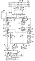
- a block diagram of the machine protection circuit is shown in the drawing.
- a contact mat 10 and a sensor mat 11 are laid on the floor, which are combined to form a step mat.
- the Contact mat 10 consists of two conductor tracks, which are electrically insulated from one another, but come into contact with one another when they are pressed together by a load, which is indicated by the switch symbol 12.
- the output line 13 of the contact mat 10 is connected to ground potential when the contact mat 10 is loaded.
- the sensor mat 11 is laid in the hazardous area, which consists of several plastic sheets lying one on top of the other, one of which is at ground potential and while the output line 14 leads to the monitoring circuit.
- the outer foils of the foil package are provided with a metal coating and the two metal coatings are connected to one another by a high-resistance resistor 15.
- the contact mat 10 and the sensor mat 11 form a common step mat which must be entered to reach the machine and cannot be skipped.
- the foot mat is wide enough to ensure that the machine comes to a standstill in good time, so that a person entering the foot mat cannot reach into the machine while it is still running.
- the signal of the output line 14 of the sensor mat 11 is fed via a capacitor 16 and an impedance converter 17 to a threshold switch 18 which generates an output signal when the signal of the sensor mat exceeds a predetermined threshold value.
- the output of the threshold switch 18 is connected via a diode 19 to the input of the first memory 20, which is designed as a flip-flop.
- the input signal is fed to the dynamic input of the flip-flop, which tilts into the set state when a pulse is received and can be reset by a signal at its reset input R.
- the output of the flip-flop 20 is connected to the driver circuit 21, which is a transistor circuit, the structure of which is not specified in detail.
- the driver circuit 21 contains a resistor 22, via which its input line is connected to the positive pole of the supply voltage.
- the input of the driver circuit 21 sets is at plus potential if it is not forcibly set to another potential by the output of the memory 20.
- positive potential corresponds to a logic "1" signal
- ground potential corresponds to logic "0" signal.
- the output of the driver circuit 21 controls the relay 23.
- all relay contacts are shown in the idle state, that is to say when the relay is de-energized.
- the relay 23 has a normally open contact 23a (when the relay is energized) and a normally closed contact 23b (when the relay is energized).
- the normally open contact 23a is in a circuit
- the safety circuit 24 and the normally closed contact 23b is in a series circuit 25.
- the signal of the output line 14 of the sensor mat 11 is also fed via a second threshold switch 26 and a diode 27 to the anode of the diode 19, which is connected to the input of the memory 20.
- the response threshold of the threshold switch 26 is higher than that of the threshold switch 18.
- the threshold switch 26 does not respond to a signal generated by stepping on the step mat, but responds to short circuit and interruption of the output line 14, e.g. as a result of sabotage. It monitors whether the voltage on line 14 is within a voltage window that has a lower and an upper limit.
- the signal of the output line 13 of the contact mat 10 is fed to a threshold switch 28, the output of which is connected via a diode 29 to the input of the memory 30.
- the memory 30 is designed in the same way as the memory 20. Its output is connected to the driver circuit 31, which is designed in the same way as the driver circuit 21 and which controls the relay 32.
- the relay 32 has a normally open contact 32a, which is in a circuit of the safety circuit 24, and a normally closed contact 32b, which is contained in the series circuit 25.
- the safety circuit 24 is a commercially available two-hand safety relay that can interrupt the supply lines L1, L2 and L3 of the machine.
- the safety circuit 24 has two relays 33 and 34, each of which closes a three-pole mains switch 35 and 36 in the excited state.
- the manually operated main switch 37 of the machine is located between the safety circuit 24 and the machine.
- the safety circuit 24 has control electronics 38 which are controlled by the respective state of the normally open contacts 23a and 32a and which in turn controls the relays 33 and 34.
- the normally open contacts 23a and 32a which are manually operated in a two-hand safety relay, must be closed within 0.5 seconds, i.e. almost simultaneously. As soon as at least one of the working contacts is opened, the safety circuit 24 switches off the machine.
- the series connection is connected via the make contact 40a of the further relay 40 to the reset inputs R of the two memories 20 and 30, so that these memories are reset when the contacts 23b, 32b and 40a are all closed when the reset switch 39 is actuated.
- the outputs of the threshold switches 18, 26 and 28 are each connected to a common line 44 via a diode 41, 42 and 43, respectively, which leads to the input of an impedance converter 45.
- the output signal of the impedance converter 45 controls the relay 40 via the threshold switch 46 and the driver circuit 47, which is designed in the same way as the driver circuit 21.
- a voltage pulse generated by pressure change on the sensor mat 11 passes through the con capacitor 16 and the impedance converter 17 to the threshold switch 18, which then generates a rectangular pulse. Because a pulse is supplied to the memory 20 via the diode 19, this memory is set, ie a "1" signal is produced at its output. The memory 20 maintains the set state until it receives ground potential at its reset input R. The relay 23 is energized as long as a "0" signal is present at the output of the memory 20; if the memory 20 is set against it, there is a "1" signal at its output, causing the relay 23 to drop out.
- the relay 23 Since the input of the driver circuit 21 is pulled to a "1" signal via the resistor 22 if there is no "0" signal at the output of the memory 20, the relay 23 drops out even if one of the leads or supply lines of the driver circuit 21 upstream components is interrupted. The relay 23 thus drops out whenever a voltage pulse has been generated by the sensor mat 11, or when a supply line has been interrupted or short-circuited.
- a short circuit generated by static pressure on the contact mat 10 leads to a "1" signal at the output of the threshold circuit 28.
- the memory 30 is set and the driver 31 de-energizes the relay 32.
- the relay 32 therefore drops out whenever a short circuit is generated by the contact mat 10 or when the supply line to the contact mat has been interrupted.
- the safety circuit 24 switches off the machine.
- the safety circuit connects the machine to the supply lines L1, L2 and L3 only when both relays 23 and 32 are energized. This is only the case if the step mat, which consists of the contact mat 10 and the sensor mat 11, has not been walked on and the signal lines are error-free. If a "1" signal occurs at the output of a threshold switch, the machine is immediately switched off by the safety circuit 24 and remains switched off due to the function of the memories 20 and 30.
- the reset switch 39 which is preferably designed as a key switch.
- a prerequisite for switching on again is that when entering the step mat 10, 11 both relays 23 and 32 have dropped out and that the step mat is no longer loaded at the current time. This is checked by the threshold switch 46 which receives no signal via the OR circuit consisting of the diodes 41, 42 and 43 when the step mat is relieved. Only in this case, the relay 40 is energized via the driver circuit 47 so that the reset signal from the reset switch 39 can reach the reset inputs R of the memories 20 and 30 via the closed contacts 23b, 32b and 40a. Only then can the machine protection circuit be switched on again and the machine restarted.
- the main switch 37 When the machine's power supply is switched on, the main switch 37 is first closed. At the same time, the memories 20 and 30 are set so that the relays 23 and 32 are without current. The machine remains switched off for the time being. To switch on, it is necessary to operate the reset switch 39, as a result of which the memories 22 and 30 have been reset if the relay 40 has picked up. The machine is therefore only switched on when both memories 20 and 30 are reset by the reset signal and the relays 23 and 32 are excited via the associated drivers 21 and 31, respectively, if the electronics function correctly during the reset. This means that the electronics are self-tested each time the machine protection circuit is switched on. If the power supply to the device fails, the relays drop out and the machine is immediately switched off.
Landscapes
- Engineering & Computer Science (AREA)
- General Engineering & Computer Science (AREA)
- Mechanical Engineering (AREA)
- Push-Button Switches (AREA)
- Burglar Alarm Systems (AREA)
- Control Of Electric Motors In General (AREA)
Claims (7)
Priority Applications (3)
| Application Number | Priority Date | Filing Date | Title |
|---|---|---|---|
| EP86109368A EP0253000B1 (fr) | 1986-07-09 | 1986-07-09 | Système de sécurité d'une machine |
| AT86109368T ATE49800T1 (de) | 1986-07-09 | 1986-07-09 | Maschinenschutzschaltung. |
| DE8686109368T DE3668492D1 (de) | 1986-07-09 | 1986-07-09 | Maschinenschutzschaltung. |
Applications Claiming Priority (1)
| Application Number | Priority Date | Filing Date | Title |
|---|---|---|---|
| EP86109368A EP0253000B1 (fr) | 1986-07-09 | 1986-07-09 | Système de sécurité d'une machine |
Publications (2)
| Publication Number | Publication Date |
|---|---|
| EP0253000A1 EP0253000A1 (fr) | 1988-01-20 |
| EP0253000B1 true EP0253000B1 (fr) | 1990-01-24 |
Family
ID=8195257
Family Applications (1)
| Application Number | Title | Priority Date | Filing Date |
|---|---|---|---|
| EP86109368A Expired - Lifetime EP0253000B1 (fr) | 1986-07-09 | 1986-07-09 | Système de sécurité d'une machine |
Country Status (3)
| Country | Link |
|---|---|
| EP (1) | EP0253000B1 (fr) |
| AT (1) | ATE49800T1 (fr) |
| DE (1) | DE3668492D1 (fr) |
Cited By (1)
| Publication number | Priority date | Publication date | Assignee | Title |
|---|---|---|---|---|
| DE102017207701A1 (de) * | 2017-05-08 | 2018-11-08 | Kuka Deutschland Gmbh | Sicherheitsvorrichtung zur Überwachung eines Arbeitsraumes eines Roboters und Roboterarbeitsplatz mit einer solchen Sicherheitsvorrichtung |
Families Citing this family (6)
| Publication number | Priority date | Publication date | Assignee | Title |
|---|---|---|---|---|
| FR2631138B1 (fr) * | 1988-05-03 | 1991-04-05 | Croguennec Philippe | Dispositif de controle du demarrage d'une machine dangereuse et de protection au voisinage d'une telle machine et procede de demarrage d'une telle machine |
| DE3838449A1 (de) * | 1988-11-12 | 1989-04-13 | Uwe Zimmermann | Einklemmschutzvorrichtung |
| SE502306C2 (sv) * | 1993-11-16 | 1995-10-02 | Liros Elektronik Ab | Säkerhetsåterställningsanordning |
| US7093350B2 (en) * | 2003-10-07 | 2006-08-22 | Mitek Holdings, Inc. | Truss fabrication system with obstruction detection device |
| DE102009014248B4 (de) * | 2009-03-20 | 2012-06-14 | Sumitomo (Shi) Demag Plastics Machinery Gmbh | Begehbarer Sicherheitsboden |
| US9409309B2 (en) | 2013-03-01 | 2016-08-09 | Mitek Holdings, Inc. | Obstruction detection device |
Family Cites Families (2)
| Publication number | Priority date | Publication date | Assignee | Title |
|---|---|---|---|---|
| US4054935A (en) * | 1976-05-28 | 1977-10-18 | Leon Ginsberg | Safety control circuit |
| CH639788A5 (en) * | 1979-03-23 | 1983-11-30 | Bircher Ag | Safety device for prompt de-activation or switchover of an installation when a dangerous situation occurs |
-
1986
- 1986-07-09 DE DE8686109368T patent/DE3668492D1/de not_active Expired - Fee Related
- 1986-07-09 EP EP86109368A patent/EP0253000B1/fr not_active Expired - Lifetime
- 1986-07-09 AT AT86109368T patent/ATE49800T1/de not_active IP Right Cessation
Cited By (2)
| Publication number | Priority date | Publication date | Assignee | Title |
|---|---|---|---|---|
| DE102017207701A1 (de) * | 2017-05-08 | 2018-11-08 | Kuka Deutschland Gmbh | Sicherheitsvorrichtung zur Überwachung eines Arbeitsraumes eines Roboters und Roboterarbeitsplatz mit einer solchen Sicherheitsvorrichtung |
| DE102017207701B4 (de) * | 2017-05-08 | 2021-04-22 | Kuka Deutschland Gmbh | Sicherheitsvorrichtung zur Überwachung eines Arbeitsraumes eines Roboters und Roboterarbeitsplatz mit einer solchen Sicherheitsvorrichtung |
Also Published As
| Publication number | Publication date |
|---|---|
| DE3668492D1 (de) | 1990-03-01 |
| EP0253000A1 (fr) | 1988-01-20 |
| ATE49800T1 (de) | 1990-02-15 |
Similar Documents
| Publication | Publication Date | Title |
|---|---|---|
| EP2017868B1 (fr) | Etage de sortie de puissance triphasée | |
| EP1493064A2 (fr) | Appareil de coupure, protegee contre les erreurs, d'un consommateur electrique, notamment dans les installations de production industrielle | |
| DE19517958A1 (de) | Motorantriebsvorrichtung für ein Kraftfahrzeug | |
| EP0253000B1 (fr) | Système de sécurité d'une machine | |
| DE69702869T2 (de) | Sicherheitsrelais | |
| DE2718798B2 (de) | Schutzschaltungsanordnung für einen Gleichstrom-Hauptstromkreis | |
| DE3642233C2 (de) | Einrichtung für die Selbstüberwachung von Relaiskontakten | |
| DE2449725C3 (de) | Zweihand-Sicherheitsschal tungsanordnung zum Einschalten einer Arbeitsmaschine und zur Auslösung eines hin- und hergehenden Arbeitshubes | |
| EP0594115B1 (fr) | Méthode pour fonctionnement d'un moteur électrique freiné électriquement et circuit de freinage associé | |
| DE19715098A1 (de) | Überwachungsschaltung | |
| EP2215533B1 (fr) | Dispositif de commande pour un système de commutation de sécurité à surveillance intégrée de la tension d'alimentation | |
| DE19751674C2 (de) | Schaltungsanordnung mit Sicherheitsfunktion | |
| DE2748632C2 (fr) | ||
| DE2713872C3 (de) | Wechselstromsicherheitsschaltung für die Fernbedienung von Maschinen | |
| EP0767478B1 (fr) | Circuit de sécurité | |
| EP0565745B1 (fr) | Surveillance d'un changement de signal, en particulier dans des systèmes de pilotage | |
| DE2614748A1 (de) | Schaltung zur funktionsueberwachung eines mittelbar wirkenden schalters | |
| DE19700898B4 (de) | Schaltungsanordnung für eine Schutzeinrichtung | |
| DE4424285A1 (de) | Zweikanalige Zweihandschaltung für elektrische Antriebe | |
| DE1087691B (de) | Steuer- und UEberwachungseinrichtung aus logischen Elementen mit selbsttaetiger UEberwachung auf innere Fehler, insbesondere als Schaltfehlerschutz in Anwendung auf Schalterbetaetigungs-einheiten fuer Anlagenbildsteuerungen | |
| DE2722893C3 (de) | Schaltungsanordnung für ein Schaltgerät in explosionsgefährdeten Betriebsstätten | |
| DE2522262A1 (de) | Elektrische sicherheitsschaltung zur zweihandeinrueckung von kraftbetaetigten arbeitsmaschinen | |
| DE1413960C (de) | Gegen innere Fehler geschützte digi tal binare Steuerung | |
| DE3434474C2 (de) | Schaltungsanordnung zur Geschwindigkeitsüberwachung für zumindest einen Motor | |
| DE2722859C2 (de) | Schaltungsanordnung für Teilnehmerstationen in Fernmelde-, insbesondere Fernsprechanlagen mit einem tastengesteuerten Wählimpulsgeber |
Legal Events
| Date | Code | Title | Description |
|---|---|---|---|
| PUAI | Public reference made under article 153(3) epc to a published international application that has entered the european phase |
Free format text: ORIGINAL CODE: 0009012 |
|
| AK | Designated contracting states |
Kind code of ref document: A1 Designated state(s): AT BE CH DE FR GB IT LI LU NL SE |
|
| 17P | Request for examination filed |
Effective date: 19880617 |
|
| 17Q | First examination report despatched |
Effective date: 19890407 |
|
| GRAA | (expected) grant |
Free format text: ORIGINAL CODE: 0009210 |
|
| AK | Designated contracting states |
Kind code of ref document: B1 Designated state(s): AT BE CH DE FR GB IT LI LU NL SE |
|
| PG25 | Lapsed in a contracting state [announced via postgrant information from national office to epo] |
Ref country code: IT Free format text: LAPSE BECAUSE OF FAILURE TO SUBMIT A TRANSLATION OF THE DESCRIPTION OR TO PAY THE FEE WITHIN THE PRE;WARNING: LAPSES OF ITALIAN PATENTS WITH EFFECTIVE DATE BEFORE 2007 MAY HAVE OCCURRED AT ANY TIME BEFORE 2007. THE CORRECT EFFECTIVE DATE MAY BE DIFFERENT FROM THE ONE RECORDED.SCRIBED TIME-LIMIT Effective date: 19900124 Ref country code: FR Effective date: 19900124 Ref country code: BE Effective date: 19900124 Ref country code: GB Effective date: 19900124 Ref country code: SE Effective date: 19900124 Ref country code: NL Effective date: 19900124 |
|
| REF | Corresponds to: |
Ref document number: 49800 Country of ref document: AT Date of ref document: 19900215 Kind code of ref document: T |
|
| REF | Corresponds to: |
Ref document number: 3668492 Country of ref document: DE Date of ref document: 19900301 |
|
| EN | Fr: translation not filed | ||
| NLV1 | Nl: lapsed or annulled due to failure to fulfill the requirements of art. 29p and 29m of the patents act | ||
| PG25 | Lapsed in a contracting state [announced via postgrant information from national office to epo] |
Ref country code: LU Free format text: LAPSE BECAUSE OF NON-PAYMENT OF DUE FEES Effective date: 19900731 |
|
| GBV | Gb: ep patent (uk) treated as always having been void in accordance with gb section 77(7)/1977 [no translation filed] | ||
| PLBE | No opposition filed within time limit |
Free format text: ORIGINAL CODE: 0009261 |
|
| STAA | Information on the status of an ep patent application or granted ep patent |
Free format text: STATUS: NO OPPOSITION FILED WITHIN TIME LIMIT |
|
| 26N | No opposition filed | ||
| PGFP | Annual fee paid to national office [announced via postgrant information from national office to epo] |
Ref country code: CH Payment date: 19940720 Year of fee payment: 9 |
|
| PGFP | Annual fee paid to national office [announced via postgrant information from national office to epo] |
Ref country code: AT Payment date: 19940725 Year of fee payment: 9 |
|
| PGFP | Annual fee paid to national office [announced via postgrant information from national office to epo] |
Ref country code: DE Payment date: 19940825 Year of fee payment: 9 |
|
| PG25 | Lapsed in a contracting state [announced via postgrant information from national office to epo] |
Ref country code: AT Effective date: 19950709 |
|
| PG25 | Lapsed in a contracting state [announced via postgrant information from national office to epo] |
Ref country code: LI Effective date: 19950731 Ref country code: CH Effective date: 19950731 |
|
| REG | Reference to a national code |
Ref country code: CH Ref legal event code: PL |
|
| PG25 | Lapsed in a contracting state [announced via postgrant information from national office to epo] |
Ref country code: DE Effective date: 19960402 |