EP0565745B1 - Surveillance d'un changement de signal, en particulier dans des systèmes de pilotage - Google Patents
Surveillance d'un changement de signal, en particulier dans des systèmes de pilotage Download PDFInfo
- Publication number
- EP0565745B1 EP0565745B1 EP92106335A EP92106335A EP0565745B1 EP 0565745 B1 EP0565745 B1 EP 0565745B1 EP 92106335 A EP92106335 A EP 92106335A EP 92106335 A EP92106335 A EP 92106335A EP 0565745 B1 EP0565745 B1 EP 0565745B1
- Authority
- EP
- European Patent Office
- Prior art keywords
- relay
- normally
- contact
- signal
- arrangement according
- Prior art date
- Legal status (The legal status is an assumption and is not a legal conclusion. Google has not performed a legal analysis and makes no representation as to the accuracy of the status listed.)
- Expired - Lifetime
Links
- 238000012544 monitoring process Methods 0.000 title claims abstract description 17
- 230000008859 change Effects 0.000 claims abstract description 7
- 238000012545 processing Methods 0.000 abstract description 3
- 238000012546 transfer Methods 0.000 abstract description 2
- 231100001261 hazardous Toxicity 0.000 abstract 4
- 230000007547 defect Effects 0.000 abstract 1
- 238000001514 detection method Methods 0.000 abstract 1
- 230000000977 initiatory effect Effects 0.000 abstract 1
- 230000002093 peripheral effect Effects 0.000 abstract 1
- 239000004020 conductor Substances 0.000 description 4
- 230000000903 blocking effect Effects 0.000 description 3
- 238000013016 damping Methods 0.000 description 2
- 238000010586 diagram Methods 0.000 description 2
- 230000005284 excitation Effects 0.000 description 2
- 239000003999 initiator Substances 0.000 description 2
- 230000001681 protective effect Effects 0.000 description 2
- 208000027418 Wounds and injury Diseases 0.000 description 1
- 230000009471 action Effects 0.000 description 1
- 230000004913 activation Effects 0.000 description 1
- 230000004888 barrier function Effects 0.000 description 1
- 230000008901 benefit Effects 0.000 description 1
- 230000006378 damage Effects 0.000 description 1
- 238000013461 design Methods 0.000 description 1
- 230000000694 effects Effects 0.000 description 1
- 208000014674 injury Diseases 0.000 description 1
- 238000011089 mechanical engineering Methods 0.000 description 1
- 238000012986 modification Methods 0.000 description 1
- 230000004048 modification Effects 0.000 description 1
- 230000003068 static effect Effects 0.000 description 1
- 239000002699 waste material Substances 0.000 description 1
Images



Classifications
-
- F—MECHANICAL ENGINEERING; LIGHTING; HEATING; WEAPONS; BLASTING
- F16—ENGINEERING ELEMENTS AND UNITS; GENERAL MEASURES FOR PRODUCING AND MAINTAINING EFFECTIVE FUNCTIONING OF MACHINES OR INSTALLATIONS; THERMAL INSULATION IN GENERAL
- F16P—SAFETY DEVICES IN GENERAL; SAFETY DEVICES FOR PRESSES
- F16P7/00—Emergency devices preventing damage to a machine or apparatus
- F16P7/02—Emergency devices preventing damage to a machine or apparatus by causing the machine to stop on the occurrence of dangerous conditions therein
Definitions
- the invention relates to an arrangement for monitoring a signal change in self-controlling control systems with a switch-off wiping relay and with a feedback circuit.
- Hydraulic presses are mainly equipped with directional valves with spring return.
- these directional control valves must be arranged in series in a safety hydraulic system and their valve pistons must be queried for the blocking position.
- two such directional valves are provided.
- a break in the piston return spring in one of the two valves could result in the valve piston sliding out of its blocking position and partially releasing the oil flow. Due to the serial arrangement of the valves, this error would initially not be noticed despite the loss of redundancy, as long as the second valve works correctly.
- a break in the piston return spring in the second valve would immediately result in the hydraulic system getting out of control because the oil flow can no longer be completely and reliably shut off when the valves are switched off.
- a dangerous movement of the hydraulic cylinder of the hydraulic press may only occur if the electrical safety circuit has proven that both valve pistons of the responsible, redundant valves have been moved out of the blocking position and not from any intermediate position in order to release the oil flow to the cylinder for the dangerous movement .
- Further Practical examples are sliding protective grilles or doors on machine tools.
- the safety controller works with relays, whose contacts are in series in the monitoring or control circuits.
- the safety control is operated by two push buttons. In practice, these are two hand switches that are located far from the press or punch in question and that must be operated accordingly by the operator with two hands in order to protect the operator from danger during the movement of the press ram.
- These engagement buttons have a double contact consisting of a break contact and a make contact. This means that two relays can be controlled inversely.
- monitoring and control circuits to, which are designed so that they carry out self-monitoring, ie in the event of electrical faults, for. B.
- Another safety circuit is known from DE-A-38 30 742, which is linked to an expansion circuit, the safety circuit and the expansion circuit each having three positively driven relays.
- the problem here is to enable the enabling current paths to be increased by means of simple circuitry measures, without compromising safety.
- the invention is based on the object of providing an arrangement which, prior to the introduction of a dangerous state or a dangerous movement of a machine, allows the starting state and the initial position to be checked by monitoring a signal change that has occurred in each case before the introduction of a dangerous state or a dangerous movement.
- the object is achieved in that at least one sensor element is provided, which is equipped with an NC contact and a NO contact, the common line point of which is connected to a supply line, the NC contact of the sensor element being connected to the one coil end of the switch-off wiping relay is connected with a defined wiping time, which is equipped with a changeover contact and an additional break contact, wherein the make contact of the encoder element is also connected to one end of the coil of another relay, which has one break and two make contacts, the break contact and the normally open contacts of the relay and the contacts of the switch-off wiper relay are positively guided, the other coil end of the switch-off wiper relay via the contact opener of the own changeover contact on the other supply line and the NO contact of this W echsler contact are connected to the other coil end of the relay and this coil end is connected in parallel to the other supply line via its own latching contact, and the normally open contact of the relay is in a safety circuit that interacts directly with the enabling circuit of the control system and the normally closed
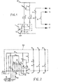
- Fig. 1 shows the basic circuit with a transmitter element 1, which may consist, for example, of a simple position switch which is controlled or actuated by a switching cam 28 moved in the direction of arrow 29.
- the encoder element 1 is equipped with an NC contact 3 and a NO contact 4.
- the common line point 31 of these contacts is connected to one supply line 5, according to FIG. 1 to the lower supply line.
- the break contact 3 is connected to the one coil end of a switch-off wiper relay 6, which has a defined wiping time.
- the switch-off wiping relay 6 is equipped with a changeover contact 7 and an additional break contact 8.
- the normally open contact 4 of the transmitter element 1 is connected to one end of the coil of a further relay 9, which in turn has an normally closed contact 10 and two normally open contacts 11 and 12.
- the contacts 10, 11 and 12 of this relay 9 and the contacts 7 and 8 of the switch-off wiping relay 6 must be positively driven.
- the other coil end of the switch-off wiping relay 6 lies above the break contact of its own changeover contact 7 on the other supply line 13, namely in FIG. 1 on the upper supply line.
- the normally open contact of this changeover contact 7 is with the second coil end of the relay 9 connected. At the same time, this coil end is connected in parallel to it via its own latching contact 11 in the form of the normally open contact shown, to the upper supply line 13 in FIG. 1.
- the normally open contact 12 of the relay 9 is located in a safety circuit with the reference numerals 14 and 15, which interacts directly with the release circuit (not shown) of a control system.
- the break contact 8 of the switch-off wiper relay 6 and the break contact 10 of the relay 9 are in a feedback circuit with the reference numerals 16 and 17.
- the coil of the switch-off wiper relay 6 is directly connected to the voltage between the supply lines 13 and 5.
- the position switch 1 for example by means of the switching cam 28, its break contact opens.
- the normally open contact 4 is closed.
- the switch-off wiper relay 6 is activated for the duration of the defined wiping time and the change-over contact 7 of the switch-off wiper relay applies the potential of the upper supply line 13 to the coil end of the relay 9 via its make function.
- the relay 9 now has the make contact 4 of the Position switch 1 with its other coil end also connects to the lower supply line 5. The relay 9 is switched on.
- the relay 9 Via its own normally open contact 11, the relay 9 goes through the connection with the upper supply line 13 in self-holding and is thus independent of the wiping time of the switch-off wiping relay 6.
- the self-holding of the relay 9 continues as long as the position switch 1 is actuated.
- the so-called safety circuit 14, 15 is thus kept closed via the make contact 12 of the relay 9.
- the safety circuit 14, 15 interacts directly with the release circuit (not shown) of a control system for the dangerous movement of the machine.
- the control system known from the beginning of EP-0 105 054 B1 has a feedback circuit.
- the switch-on conditions from the periphery for the start of a dangerous movement can be combined in such a feedback circuit.
- the circuit 16, 17 shown in simplified form forms part of such a feedback circuit with the break contact 8 of the switch-off wiping relay 6 and the break contact 10 of the relay 9.
- a start command in the control system for a dangerous movement cannot occur if the switch-off wiping relay 6 or the relay 9 are switched on incorrectly by a previous activation or by manipulation and keep the circuit 16, 17 with the break contacts 8 and / or 10 open at the time the machine is started .
- the reset control of the position switch 1 is thus forced cyclically via the switch-off wiping relay 6.
- the encoder element 1 shown in FIG. 1 can not only consist of a simple position switch, but it can also optionally have a safety limit switch or a proximity switch or a sensor or another suitable signal transmitter.
- Fig. 2 shows a completed electrical circuit of the arrangement according to the invention.
- the circuit is based on the basic circuit of FIG. 1, so that the same reference numerals 3 to 17 from FIG. 1 have been used for the same or equivalent parts.
- the monitoring circuit is accommodated in a housing 30 which is closed and is normally not accessible from the outside.
- the housing In the housing are relays 6 and 9 and another Relay 19 housed with all their relay contacts.
- the housing is provided with housing connection clamps for external connections.
- the connection terminals are shown in partially filled circles lying on the dash-dotted lines, for example at reference number 24.
- the external position switch 1 shown in FIG. 1 has been replaced by an internal mini relay 19, which also has an NC contact 3 and a NO contact 4.
- the mini-relay 19 fulfills the same function as the position switch 1.
- the input signal can now also be generated by a single contact, any sensor, or, as shown in FIG. 2, by a proximity switch 18 as a transmitter element.
- 2 also shows an external line connection 22.
- the line connection 22 which sets the one coil end of the mini relay 19 to a fixed potential of the supply voltage, is connected to the lower supply line 5 or to the upper supply line 13
- proximity switches 18 can be used as proximity switches pnp or npn types can be connected.
- npn and pnp transistors are terms generally known in the art in connection with a transistor type, that is to say a distinction is made between npn and pnp transistors.
- An npn transistor has two outer negative n-conductors and a positive p-conductor in the middle with boundary layers in between.
- a pnp transistor has two outer positive p-conductors and a negative n-conductor in between.
- the line 23 detects the actual input signal of the proximity switch 18 or of the sensor or initiator at the other coil connection to the outside.
- a further normally open contact 27 is assigned in the relay 9, which forms a further potential-free safety circuit 25, 26 in order - if necessary - to control two separate safety-relevant circuits of the control system of the machine, e.g. B. a forward and backward movement.
- the mode of operation of the circuit according to FIG. 2 is essentially based on the mode of operation which has been explained for FIG. 1.
- a transmitter element 18 or a signal generator in the form of a pnp proximity switch as a three-wire type with a normally open function is assumed as an exemplary embodiment, the damping of which causes the mini-relay 19 to be excited.
- the mini relay is connected on the one hand via line 23 and on the other hand via line 22 to the lower supply line 5 and is thus supplied with voltage.
- the coil of the switch-off wiper relay 6 was energized via the unactuated break contact 3 and its own changeover contact 7.
- the break contact 3 and the make contact 4 are switched and the one coil end of the relay 9 is connected via line 21 to the lower supply line 5.
- the change-over contact 7 of the switch-off wiping relay 6 places the other coil end of the relay 9 at the potential of the upper supply line 13. This energizes the relay 9 and maintains its own normally open contact 11, which remains as long as the damping of the proximity switch 18 continues .
- the contacts 12 and 27 close in the output circuits 14, 15 and 25, 26.
- the circuit 16, 17, the Part of the feedback circuit in the control system does not allow the dangerous machine movement to be switched on again if the break contact 8 of the switch-off wiping relay 6 and the break contact 10 of the relay 9 should not have dropped out during de-excitation after a previous switching operation.
- the end result is self-monitoring signal acquisition and processing.
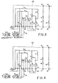
- FIG. 2 With the same basic circuit according to FIG. 2, which is accommodated in the housing 30 or which is framed by the dash-dotted line, one can now implement numerous variants of the arrangement according to the invention, which are shown in FIGS. 3 to 12.
- the special proximity switch 18 according to FIG. 2 numerous other types of transmitter elements can be used, which are also provided with the reference symbol 18 in FIGS. 3 to 10 in order to simplify the comparison.
- other components can be added or the proximity switches can be replaced by other sensor elements.
- the wiring or wire jumpers provided for this purpose on the housing can be changed, depending on whether the initiators are damped or not, as shown in the drawing. This initially results in ten different basic circuits, which are shown in FIGS. 3 to 12.
- transmitter elements or signal transmitters are used, which are indicated alternatively in the figures. Since several types of transmitter elements can be connected to most basic circuits, the number of different variants of transmitter elements or signal transmitters increases to a total of twenty-six. The signal change of all of these transmitter elements can be reliably detected and monitored with the circuit arrangement according to the invention.
Landscapes
- Engineering & Computer Science (AREA)
- General Engineering & Computer Science (AREA)
- Mechanical Engineering (AREA)
- Safety Devices In Control Systems (AREA)
- Selective Calling Equipment (AREA)
- Burglar Alarm Systems (AREA)
- Treatment Of Sludge (AREA)
- Lubrication Of Internal Combustion Engines (AREA)
- Keying Circuit Devices (AREA)
- Testing Or Calibration Of Command Recording Devices (AREA)
- Supply And Distribution Of Alternating Current (AREA)
- Stabilization Of Oscillater, Synchronisation, Frequency Synthesizers (AREA)
Claims (8)
- Arrangement pour la surveillance d'un changement de signal dans des systèmes de pilotage comprenant un relais au contact de passage au relâchement (6) ainsi qu'une boucle de rétroaction (16,17), caractérisé en ce qu'est pourvu au moins un émetteur (1;18) équipé d'un contact repos (3) et d'un contact contacteur (4) dont le point de ligne commun (31) est relié à une ligne d'alimentation (5), le contact repos (3) de l'émetteur (1;18) étant relié, avec un temps de passage défini, à l'une des extrémités de la bobine du relais au contact de passage au relâchement (6) qui est équipé d'un contact inverseur (7) et d'un contact repos additionel (8), le contact contacteur (4) de l'émetteur (1;18) étant relié en outre à l'une des extrémités de la bobine d'un autre relais (9) ayant un contact repos (10) et deux contacts contacteurs (11,12), le contact repos (10) et les contacts contacteurs (11,12) du relais (9) ainsi que les contacts (7,8) du relais au contact de passage au relâchement (6) en outre étant guidés, l'autre extrémité de la bobine du relais au contact de passage au relâchement (6), par le contact repos de l'inverseur propre (7), étant relié à l'autre ligne d'alimentation (13), et le contact contacteur dudit inverseur (7) étant relié à l'autre extrémité de la bobine du relais (9), et ladite extrémité de la bobine, par le contact à auto-entretien propre (11), étant relié de manière parallele à l'autre ligne d'alimentation (13), et le contact contacteur (12) du relais (9) étant situé dans un circuit de sécurité qui coopère directement avec le circuit de relâchement du système de pilotage, et le contact repos (8) du relais au contact de passage au relâchement (6) et le contact contacteur (10) du relais (9) étant situés dans la boucle de rétroaction (16,17).
- Arrangement selon la revendication 1, caractérisé par une boîte fermée (30) dans laquelle sont logés toutes les relais (6,9;19) avec leur contacts de relais, et ladite boîte étant pourvue des bornes de raccordement (24) pour des raccordements externes.
- Arrangement selon la revendication 1 ou 2, caractérisé en ce que l'émetteur (1;18), d'une façon facultative, a un actionneur de positionnement ou un limiteur extrême de course ou un détecteur de proximité ou un capteur.
- Arrangement selon l'une quelconque des revendications précédentes, caractérisé par un relais miniature interne (19).
- Arrangement selon la revendication 3, caractérisé en ce que comme détecteurs de proximité on a choisi les types pnp ou npn.
- Arrangement selon l'une quelconque des revendications précédentes, caractérisé en ce que, pour la surveillance facultative du changement de signal de BAS vers HAUT ou de HAUT vers BAS, des liaisons externes par fils (20,21) sur les connexions des bobines des relais (6) sont échangeables.
- Arrangement selon l'une quelconque des revendications précédentes, caractérisé en ce que, pour la surveillance facultative du changement de signal de BAS vers HAUT ou de HAUT vers BAS, l'émetteur (1;18) à une fonction contacteur ou une fonction repos.
- Arrangement selon l'une quelconque des revendications précédentes, caractérisé en ce que le relais (9) a un autre contact contacteur (27) étant situé dans un autre circuit de sécurité (25,26) libre de potentiel.
Priority Applications (7)
| Application Number | Priority Date | Filing Date | Title |
|---|---|---|---|
| DK92106335.0T DK0565745T3 (da) | 1992-04-13 | 1992-04-13 | Overvågning af et signalskift, i særdeleshed i selvkontrollerende styresystemer |
| ES92106335T ES2089274T3 (es) | 1992-04-13 | 1992-04-13 | Vigilancia de un cambio de señal, especialmente en sistemas de mando autocontrolables. |
| AT92106335T ATE140322T1 (de) | 1992-04-13 | 1992-04-13 | Überwachung eines signalwechsels, insbesondere in selbstkontrollierenden steuerungssystemen |
| DE59206746T DE59206746D1 (de) | 1992-04-13 | 1992-04-13 | Überwachung eines Signalwechsels, insbesondere in selbstkontrollierenden Steuerungssystemen |
| EP92106335A EP0565745B1 (fr) | 1992-04-13 | 1992-04-13 | Surveillance d'un changement de signal, en particulier dans des systèmes de pilotage |
| JP5080580A JPH0626598A (ja) | 1992-04-13 | 1993-04-07 | 信号変化の監視装置 |
| US08/045,139 US5436789A (en) | 1992-04-13 | 1993-04-12 | Signal-change surveillance equipment, in particular for use in self-checking control systems |
Applications Claiming Priority (1)
| Application Number | Priority Date | Filing Date | Title |
|---|---|---|---|
| EP92106335A EP0565745B1 (fr) | 1992-04-13 | 1992-04-13 | Surveillance d'un changement de signal, en particulier dans des systèmes de pilotage |
Publications (2)
| Publication Number | Publication Date |
|---|---|
| EP0565745A1 EP0565745A1 (fr) | 1993-10-20 |
| EP0565745B1 true EP0565745B1 (fr) | 1996-07-10 |
Family
ID=8209539
Family Applications (1)
| Application Number | Title | Priority Date | Filing Date |
|---|---|---|---|
| EP92106335A Expired - Lifetime EP0565745B1 (fr) | 1992-04-13 | 1992-04-13 | Surveillance d'un changement de signal, en particulier dans des systèmes de pilotage |
Country Status (7)
| Country | Link |
|---|---|
| US (1) | US5436789A (fr) |
| EP (1) | EP0565745B1 (fr) |
| JP (1) | JPH0626598A (fr) |
| AT (1) | ATE140322T1 (fr) |
| DE (1) | DE59206746D1 (fr) |
| DK (1) | DK0565745T3 (fr) |
| ES (1) | ES2089274T3 (fr) |
Families Citing this family (2)
| Publication number | Priority date | Publication date | Assignee | Title |
|---|---|---|---|---|
| FR2792416B1 (fr) * | 1999-04-16 | 2001-06-08 | Texton | Procede de controle de la fin de course d'un organe mobile et dispositif pour sa mise en oeuvre |
| US10447026B2 (en) * | 2016-12-23 | 2019-10-15 | Ripd Ip Development Ltd | Devices for active overvoltage protection |
Citations (1)
| Publication number | Priority date | Publication date | Assignee | Title |
|---|---|---|---|---|
| EP0105054A1 (fr) * | 1982-10-01 | 1984-04-11 | Square D Starkstrom GmbH | Circuit pour le contrôle actif d'interrupteurs de fin de course rangés par paires |
Family Cites Families (9)
| Publication number | Priority date | Publication date | Assignee | Title |
|---|---|---|---|---|
| US3089985A (en) * | 1960-10-27 | 1963-05-14 | Western Electric Co | Safety circuit |
| DE2319626C2 (de) * | 1973-04-18 | 1984-04-26 | Maschinenfabrik Müller-Weingarten AG, 7987 Weingarten | Elektrische Sicherheitssteuerung für Pressen, Stanzen und dergleichen |
| US3914621A (en) * | 1974-10-07 | 1975-10-21 | Gen Electric | Circuit for enabling safe actuation of a machine |
| DE2818173B1 (de) * | 1978-04-26 | 1979-03-29 | Starkstrom Schaltgeraetefabrik | Anordnung zur elektrischen UEberwachung von Pressensicherheitsventilen |
| DE3028196C2 (de) * | 1980-07-25 | 1984-03-08 | Pilz Apparatebau Gmbh & Co, 7302 Ostfildern | Zweikanalige Zweihandschaltung für kraftbetriebene Pressen |
| US4392176A (en) * | 1981-12-21 | 1983-07-05 | The Goodyear Tire & Rubber Company | Self-checking safety mat |
| DD249166A3 (de) * | 1985-04-09 | 1987-09-02 | Werkzeugmaschinenfabrik Zeulen | Sicherheitsschaltung fuer pressen |
| US4775913A (en) * | 1987-09-02 | 1988-10-04 | Ekblad Carl A | Safety shutoff device for a stove |
| DE3830742A1 (de) * | 1988-09-09 | 1990-03-22 | Elan Schaltelemente Gmbh | Sicherheitsschaltung |
-
1992
- 1992-04-13 AT AT92106335T patent/ATE140322T1/de not_active IP Right Cessation
- 1992-04-13 ES ES92106335T patent/ES2089274T3/es not_active Expired - Lifetime
- 1992-04-13 DK DK92106335.0T patent/DK0565745T3/da active
- 1992-04-13 DE DE59206746T patent/DE59206746D1/de not_active Expired - Fee Related
- 1992-04-13 EP EP92106335A patent/EP0565745B1/fr not_active Expired - Lifetime
-
1993
- 1993-04-07 JP JP5080580A patent/JPH0626598A/ja active Pending
- 1993-04-12 US US08/045,139 patent/US5436789A/en not_active Expired - Fee Related
Patent Citations (1)
| Publication number | Priority date | Publication date | Assignee | Title |
|---|---|---|---|---|
| EP0105054A1 (fr) * | 1982-10-01 | 1984-04-11 | Square D Starkstrom GmbH | Circuit pour le contrôle actif d'interrupteurs de fin de course rangés par paires |
Also Published As
| Publication number | Publication date |
|---|---|
| JPH0626598A (ja) | 1994-02-01 |
| EP0565745A1 (fr) | 1993-10-20 |
| DE59206746D1 (de) | 1996-08-14 |
| DK0565745T3 (da) | 1996-11-11 |
| ES2089274T3 (es) | 1996-10-01 |
| ATE140322T1 (de) | 1996-07-15 |
| US5436789A (en) | 1995-07-25 |
Similar Documents
| Publication | Publication Date | Title |
|---|---|---|
| EP1262021B2 (fr) | Appareil de commutation de securite et systeme d'appareils de commutation de securite | |
| EP1982105B1 (fr) | Dispositif de commutation de sécurité et procédé de mise en circuit et hors circuit sécurisée d'une charge électrique avec un microcontrôleur | |
| EP3192091B1 (fr) | Interrupteur d'arrêt d'urgence adaptable contrôlé | |
| DE10027156A1 (de) | Schutzeinrichtung für Maschinen, wie Abkantpressen, Schneidmaschinen, Stanzmaschinen oder dergleichen | |
| WO2003085313A2 (fr) | Appareil de coupure, protegee contre les erreurs, d'un consommateur electrique, notamment dans les installations de production industrielle | |
| EP2845072A1 (fr) | Appareil de commande | |
| EP1662195A1 (fr) | Dispositif de sécurité et procédé pour détérminer la course d'inertie d'une machine | |
| DE4410103C1 (de) | Antrieb der fluidischen oder elektrischen Bauart mit einer Steuerung | |
| EP3137948B1 (fr) | Dispositif et procédé de surveillance d'une partie de machine mobile avec protection contre les erreurs | |
| EP1887444B1 (fr) | Commande de processus | |
| WO2005047759A2 (fr) | Dispositif et procede pour realiser la commutation sans erreur d'un recepteur inductif | |
| DE4409541A1 (de) | Sicherheitstechnische Einrichtung | |
| DE69614238T2 (de) | Zweihand-Steuerschaltung für Pressen | |
| DE10255066B4 (de) | Mehrkreis-Lenksystem | |
| EP0446651A2 (fr) | Système d'actionnement électropneumatique de porte de véhicule de transport de passagers | |
| DE3743338C2 (fr) | ||
| EP2215533B1 (fr) | Dispositif de commande pour un système de commutation de sécurité à surveillance intégrée de la tension d'alimentation | |
| EP0565745A1 (fr) | Surveillance d'un changement de signal, en particulier dans des systèmes de pilotage | |
| EP0253000A1 (fr) | Système de sécurité d'une machine | |
| DE69614987T2 (de) | Steuereinrichtung eines Doppelventils | |
| DE10050542B4 (de) | Sicherheitsschaltung gegen eine unerwünschte Inbetriebnahme eines Montageautomaten insbesondere während des Einrichtbetriebes sowie Verfahren zum Zuschalten der Sicherheitsschaltung | |
| DE4213171A1 (de) | Sicherheitsschaltung | |
| DE102014119269B4 (de) | Elektrische Pressvorrichtung und Verfahren zu deren Steuerung | |
| DE3038682C2 (de) | Bohr- und Gewindeschneidmaschine mit Sicherheitsschalteinrichtung | |
| DE10063674B4 (de) | Numerische Steuerung und Verfahren zum automatischen Freifahren einer Achse nach einem Überfahren sicherer Endlagen |
Legal Events
| Date | Code | Title | Description |
|---|---|---|---|
| PUAI | Public reference made under article 153(3) epc to a published international application that has entered the european phase |
Free format text: ORIGINAL CODE: 0009012 |
|
| 17P | Request for examination filed |
Effective date: 19930707 |
|
| AK | Designated contracting states |
Kind code of ref document: A1 Designated state(s): AT BE CH DE DK ES FR GB GR IT LI LU MC NL PT SE |
|
| 17Q | First examination report despatched |
Effective date: 19940406 |
|
| GRAH | Despatch of communication of intention to grant a patent |
Free format text: ORIGINAL CODE: EPIDOS IGRA |
|
| GRAH | Despatch of communication of intention to grant a patent |
Free format text: ORIGINAL CODE: EPIDOS IGRA |
|
| RAP1 | Party data changed (applicant data changed or rights of an application transferred) |
Owner name: SCHNEIDER ELECTRIC GMBH |
|
| GRAA | (expected) grant |
Free format text: ORIGINAL CODE: 0009210 |
|
| AK | Designated contracting states |
Kind code of ref document: B1 Designated state(s): AT BE CH DE DK ES FR GB GR IT LI LU MC NL PT SE |
|
| PG25 | Lapsed in a contracting state [announced via postgrant information from national office to epo] |
Ref country code: GR Free format text: LAPSE BECAUSE OF FAILURE TO SUBMIT A TRANSLATION OF THE DESCRIPTION OR TO PAY THE FEE WITHIN THE PRESCRIBED TIME-LIMIT Effective date: 19960710 |
|
| REF | Corresponds to: |
Ref document number: 140322 Country of ref document: AT Date of ref document: 19960715 Kind code of ref document: T |
|
| REG | Reference to a national code |
Ref country code: CH Ref legal event code: NV Representative=s name: HEPP, WENGER & RYFFEL AG |
|
| REF | Corresponds to: |
Ref document number: 59206746 Country of ref document: DE Date of ref document: 19960814 |
|
| ITF | It: translation for a ep patent filed | ||
| REG | Reference to a national code |
Ref country code: ES Ref legal event code: FG2A Ref document number: 2089274 Country of ref document: ES Kind code of ref document: T3 |
|
| PG25 | Lapsed in a contracting state [announced via postgrant information from national office to epo] |
Ref country code: PT Effective date: 19961010 |
|
| GBT | Gb: translation of ep patent filed (gb section 77(6)(a)/1977) |
Effective date: 19961001 |
|
| ET | Fr: translation filed | ||
| REG | Reference to a national code |
Ref country code: DK Ref legal event code: T3 |
|
| REG | Reference to a national code |
Ref country code: ES Ref legal event code: FG2A Ref document number: 2089274 Country of ref document: ES Kind code of ref document: T3 |
|
| PGFP | Annual fee paid to national office [announced via postgrant information from national office to epo] |
Ref country code: NL Payment date: 19970320 Year of fee payment: 6 |
|
| PGFP | Annual fee paid to national office [announced via postgrant information from national office to epo] |
Ref country code: AT Payment date: 19970324 Year of fee payment: 6 |
|
| PGFP | Annual fee paid to national office [announced via postgrant information from national office to epo] |
Ref country code: ES Payment date: 19970414 Year of fee payment: 6 |
|
| PGFP | Annual fee paid to national office [announced via postgrant information from national office to epo] |
Ref country code: CH Payment date: 19970424 Year of fee payment: 6 |
|
| PGFP | Annual fee paid to national office [announced via postgrant information from national office to epo] |
Ref country code: SE Payment date: 19970425 Year of fee payment: 6 |
|
| PGFP | Annual fee paid to national office [announced via postgrant information from national office to epo] |
Ref country code: LU Payment date: 19970509 Year of fee payment: 6 |
|
| PGFP | Annual fee paid to national office [announced via postgrant information from national office to epo] |
Ref country code: BE Payment date: 19970515 Year of fee payment: 6 |
|
| PLBE | No opposition filed within time limit |
Free format text: ORIGINAL CODE: 0009261 |
|
| STAA | Information on the status of an ep patent application or granted ep patent |
Free format text: STATUS: NO OPPOSITION FILED WITHIN TIME LIMIT |
|
| 26N | No opposition filed | ||
| PG25 | Lapsed in a contracting state [announced via postgrant information from national office to epo] |
Ref country code: MC Effective date: 19971031 |
|
| PG25 | Lapsed in a contracting state [announced via postgrant information from national office to epo] |
Ref country code: DE Free format text: LAPSE BECAUSE OF NON-PAYMENT OF DUE FEES Effective date: 19980101 |
|
| PG25 | Lapsed in a contracting state [announced via postgrant information from national office to epo] |
Ref country code: LU Free format text: LAPSE BECAUSE OF NON-PAYMENT OF DUE FEES Effective date: 19980413 Ref country code: AT Free format text: LAPSE BECAUSE OF NON-PAYMENT OF DUE FEES Effective date: 19980413 |
|
| PG25 | Lapsed in a contracting state [announced via postgrant information from national office to epo] |
Ref country code: SE Free format text: LAPSE BECAUSE OF NON-PAYMENT OF DUE FEES Effective date: 19980414 Ref country code: ES Free format text: LAPSE BECAUSE OF NON-PAYMENT OF DUE FEES Effective date: 19980414 |
|
| PG25 | Lapsed in a contracting state [announced via postgrant information from national office to epo] |
Ref country code: BE Free format text: LAPSE BECAUSE OF NON-PAYMENT OF DUE FEES Effective date: 19980430 Ref country code: CH Free format text: LAPSE BECAUSE OF NON-PAYMENT OF DUE FEES Effective date: 19980430 Ref country code: LI Free format text: LAPSE BECAUSE OF NON-PAYMENT OF DUE FEES Effective date: 19980430 |
|
| BERE | Be: lapsed |
Owner name: SCHNEIDER ELECTRIC G.M.B.H. Effective date: 19980430 |
|
| PG25 | Lapsed in a contracting state [announced via postgrant information from national office to epo] |
Ref country code: NL Free format text: LAPSE BECAUSE OF NON-PAYMENT OF DUE FEES Effective date: 19981101 |
|
| REG | Reference to a national code |
Ref country code: CH Ref legal event code: PL |
|
| NLV4 | Nl: lapsed or anulled due to non-payment of the annual fee |
Effective date: 19981101 |
|
| EUG | Se: european patent has lapsed |
Ref document number: 92106335.0 |
|
| REG | Reference to a national code |
Ref country code: ES Ref legal event code: FD2A Effective date: 20000503 |
|
| REG | Reference to a national code |
Ref country code: GB Ref legal event code: IF02 |
|
| PGFP | Annual fee paid to national office [announced via postgrant information from national office to epo] |
Ref country code: DK Payment date: 20060321 Year of fee payment: 15 |
|
| PGFP | Annual fee paid to national office [announced via postgrant information from national office to epo] |
Ref country code: GB Payment date: 20060330 Year of fee payment: 15 |
|
| PGFP | Annual fee paid to national office [announced via postgrant information from national office to epo] |
Ref country code: IT Payment date: 20060430 Year of fee payment: 15 |
|
| REG | Reference to a national code |
Ref country code: DK Ref legal event code: EBP |
|
| GBPC | Gb: european patent ceased through non-payment of renewal fee |
Effective date: 20070413 |
|
| PG25 | Lapsed in a contracting state [announced via postgrant information from national office to epo] |
Ref country code: DK Free format text: LAPSE BECAUSE OF NON-PAYMENT OF DUE FEES Effective date: 20070430 Ref country code: GB Free format text: LAPSE BECAUSE OF NON-PAYMENT OF DUE FEES Effective date: 20070413 |
|
| PGFP | Annual fee paid to national office [announced via postgrant information from national office to epo] |
Ref country code: FR Payment date: 20070306 Year of fee payment: 16 |
|
| REG | Reference to a national code |
Ref country code: FR Ref legal event code: ST Effective date: 20081231 |
|
| PG25 | Lapsed in a contracting state [announced via postgrant information from national office to epo] |
Ref country code: FR Free format text: LAPSE BECAUSE OF NON-PAYMENT OF DUE FEES Effective date: 20080430 |
|
| PG25 | Lapsed in a contracting state [announced via postgrant information from national office to epo] |
Ref country code: IT Free format text: LAPSE BECAUSE OF NON-PAYMENT OF DUE FEES Effective date: 20070413 |