EP0253075B1 - Moteur à combustion interne multicylindre avec deux turbo-compresseurs de suralimentation des gaz d'échappement - Google Patents
Moteur à combustion interne multicylindre avec deux turbo-compresseurs de suralimentation des gaz d'échappement Download PDFInfo
- Publication number
- EP0253075B1 EP0253075B1 EP87105927A EP87105927A EP0253075B1 EP 0253075 B1 EP0253075 B1 EP 0253075B1 EP 87105927 A EP87105927 A EP 87105927A EP 87105927 A EP87105927 A EP 87105927A EP 0253075 B1 EP0253075 B1 EP 0253075B1
- Authority
- EP
- European Patent Office
- Prior art keywords
- internal combustion
- combustion engine
- control
- value
- valve
- Prior art date
- Legal status (The legal status is an assumption and is not a legal conclusion. Google has not performed a legal analysis and makes no representation as to the accuracy of the status listed.)
- Expired - Lifetime
Links
Images


Classifications
-
- F—MECHANICAL ENGINEERING; LIGHTING; HEATING; WEAPONS; BLASTING
- F02—COMBUSTION ENGINES; HOT-GAS OR COMBUSTION-PRODUCT ENGINE PLANTS
- F02B—INTERNAL-COMBUSTION PISTON ENGINES; COMBUSTION ENGINES IN GENERAL
- F02B37/00—Engines characterised by provision of pumps driven at least for part of the time by exhaust
- F02B37/007—Engines characterised by provision of pumps driven at least for part of the time by exhaust with exhaust-driven pumps arranged in parallel, e.g. at least one pump supplying alternatively
-
- F—MECHANICAL ENGINEERING; LIGHTING; HEATING; WEAPONS; BLASTING
- F02—COMBUSTION ENGINES; HOT-GAS OR COMBUSTION-PRODUCT ENGINE PLANTS
- F02B—INTERNAL-COMBUSTION PISTON ENGINES; COMBUSTION ENGINES IN GENERAL
- F02B37/00—Engines characterised by provision of pumps driven at least for part of the time by exhaust
- F02B37/12—Control of the pumps
- F02B37/18—Control of the pumps by bypassing exhaust from the inlet to the outlet of turbine or to the atmosphere
-
- F—MECHANICAL ENGINEERING; LIGHTING; HEATING; WEAPONS; BLASTING
- F01—MACHINES OR ENGINES IN GENERAL; ENGINE PLANTS IN GENERAL; STEAM ENGINES
- F01N—GAS-FLOW SILENCERS OR EXHAUST APPARATUS FOR MACHINES OR ENGINES IN GENERAL; GAS-FLOW SILENCERS OR EXHAUST APPARATUS FOR INTERNAL-COMBUSTION ENGINES
- F01N13/00—Exhaust or silencing apparatus characterised by constructional features
- F01N13/08—Other arrangements or adaptations of exhaust conduits
- F01N13/10—Other arrangements or adaptations of exhaust conduits of exhaust manifolds
- F01N13/107—More than one exhaust manifold or exhaust collector
-
- Y—GENERAL TAGGING OF NEW TECHNOLOGICAL DEVELOPMENTS; GENERAL TAGGING OF CROSS-SECTIONAL TECHNOLOGIES SPANNING OVER SEVERAL SECTIONS OF THE IPC; TECHNICAL SUBJECTS COVERED BY FORMER USPC CROSS-REFERENCE ART COLLECTIONS [XRACs] AND DIGESTS
- Y02—TECHNOLOGIES OR APPLICATIONS FOR MITIGATION OR ADAPTATION AGAINST CLIMATE CHANGE
- Y02T—CLIMATE CHANGE MITIGATION TECHNOLOGIES RELATED TO TRANSPORTATION
- Y02T10/00—Road transport of goods or passengers
- Y02T10/10—Internal combustion engine [ICE] based vehicles
- Y02T10/12—Improving ICE efficiencies
Definitions
- the invention relates to an internal combustion engine according to the preamble of the main claim.
- the advantages of the invention are primarily to be seen in the fact that the charging system according to DE-OS 34 20 015 is further optimized by a targeted electronic regulation or control system which is adapted to the different operating conditions of the internal combustion engine, including the charging system, and a drop in performance. or torque behavior of the overall system is practically no longer noticeable.
- the internal combustion engine charged in this way has an overall behavior which corresponds to an internal combustion engine with a much larger volume and a higher number of cylinders. In addition, it is achieved that the internal combustion engine and the charging system are reliably protected against overload / damage.
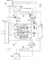
- Fig. 1, 1 is an exhaust gas turbocharger system shown for an internal combustion engine 2.
- Cylinders 3 to 8 are divided into two groups (not necessarily).
- the exhaust pipes from the cylinders open into a common exhaust gas pipe 9, from which an exhaust gas division 10 for driving a turbine 11 of a first exhaust gas turbocharger 12 and a further exhaust gas line 13 for driving a turbine 14 of a second exhaust gas turbocharger 15 emanate.
- the output of the turbines 11 and 14 can either be guided via a front silencer 16, 17 or catalytic converters or also directly via pipes into an end silencer 18.
- an additional valve 19 is inserted, which can be arranged both in front of and behind the turbine 14. Furthermore, the exhaust manifold 9 is connected to the rear silencer 18 via a blow-off valve (wastegate) 20. Cut-in valve 19 and blow-off valve 20 are pneumatically operated valves that are open when not activated. Pneumatic auxiliary energy, which is taken from a manifold intake pipe 21 upstream of a power control element (throttle valve) 22, is supplied to the valves 19, 20 via control valves 23, 24 assigned to them. The electrically operated control valves 23, 24 are acted upon by a control unit 25 with a pulse duty factor and are closed in the non-activated state.
- a control unit 25 with a pulse duty factor
- a control chamber of the connecting valve 19 or the relief valve 20 is more or less with a high pressure medium (via the pressure tapping point in the manifold 21 upstream of the throttle valve 22) or with a low pressure medium, for example the atmosphere (depending on the duty cycle). Pressure tapping point in the air filter 32) connected, the control chamber being at atmospheric pressure when the control valves 23, 24 are not activated; For reasons of clarity, such an observation has been omitted in FIG. 1.
- the compressors 26, 27 driven by the turbines 11 and 14 convey compressed air via charge air cooler 28 to the manifold intake pipe 21; from the manifold 21, the charge air is evenly distributed to the individual intake pipes to the cylinders 3 to 8.
- a check valve 31 is used, as is described in DE-OS 34 20 015.
- a vent valve 33 is inserted; this can be controlled via the control device 25.
- control unit detects signals from a speed sensor 34 (speed nmot of crankshaft 35 of engine 2), a throttle valve position sensor 36 (position of throttle valve 24, throttle valve angle dkwin), an intake manifold pressure sensor 37 (intake manifold pressure pist in intake manifold 22, downstream of the throttle valve) and one Temperature sensor 38 (charge air temperature tll), which it converts into corresponding control signals for the control valves 23, 24 of the cut-in valve 19 and the blow-off valve 20 and for the vent valve 33.
- speed sensor 34 speed nmot of crankshaft 35 of engine 2
- throttle valve position sensor 36 position of throttle valve 24, throttle valve angle dkwin
- intake manifold pressure sensor 37 intake manifold pressure pist in intake manifold 22, downstream of the throttle valve
- Temperature sensor 38 charge air temperature tll
- the control unit is constructed using microcomputer technology known per se and essentially comprises a single-chip microcomputer or a microprocessor, for example of the 8031 type from Intel, volatile and non-volatile memory, analog or digital input and output modules, and adaptation and driver modules. Individual regulation and control modules are implemented as software and are stored in the non-volatile memories together with characteristic curves and maps recorded, quantized and digitized at support points.
- Intake manifold pressure pist, charge air temperature tll, rotational speed nmot and throttle valve angle dkwin are recorded in analog or digital form or can also be made available to control unit 25 by an engine management computer. Analog variables are converted into signals that can be used by the microprocessor using an A / D converter.
- control unit can also be constructed discretely from analog / digital components / modules.
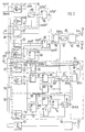
- Fig. 2 the functions of the control unit are shown as a block diagram of control or regulation modules.
- the control of the two valves in the exhaust system (the auxiliary valve 19 and the blow-off valve 20 or their control valves 23, 24) is carried out in principle according to a pilot control (pilot control module 39) which is dependent on the state variables of the internal combustion engines and which is superimposed on a control (control module 40) which is at least dependent on the intake manifold pressure .
- the control value is subjected to suitable static and dynamic limits.
- the feedforward control takes place via characteristic maps 41, 42, which assign a duty cycle characteristic map value tvhk or duty cycle hysteresis value tvhh for the duty cycle to a pair of values of the state variables (rotational speed nmot and throttle angle angle dkwin).
- the controller 40 has a PID-like structure, the setpoint (psoll, setpoint specification module 43) and the controller parameters (rki, rkp, rkd) being dependent on the operating point and being made available via characteristic maps 45-47 as a function of speed nmot and throttle valve angle dkwin.
- a correction correction module 48 dependent on the charge air temperature tll, pre-control and setpoint psoll 'are acted upon, with an increase in the charge air temperature tll acting on the boost pressure in a performance-reducing sense in order to prevent knocking of the internal combustion engine 2.
- control module 49 the values of precontrol tvhkf and control dtvh are put together, 50 subjected to suitable static and dynamic limiting or adaptation functions, 51, split into control signals tzv or wg for the connecting valve 19 or exhaust valve 20, converted into duty cycles and via a driver stage 52 to the control valves le 23 and 24 led.
- vent valve 33 is controlled via a hysteresis map 53, which determines from a pair of values from the intake manifold pressure pist and the engine speed nmot whether the vent valve 33 should be opened or closed, and a driver stage 54; this avoids pumping operation of the second exhaust gas turbocharger 15. Furthermore, when the charge pressure builds up, a pressure surge occurs in the section 29 of the charge air line 30 due to the closing of the valve 33, so that a valve body of the check valve 30 (shown in DE-OS 34 20 015) is supported when lifting off its seat.
- connection valve 19 enables a continuously adjustable application of exhaust gas to the second exhaust gas turbocharger 15 and an acceleration of its supercharger shaft.
- the amount of exhaust gas flowing off at the same time reduces the amount of exhaust gas flowing into the first exhaust gas turbocharger 12, so that the function of the cut-in valve 19 - with respect to the first exhaust gas turbocharger - corresponds to that of a wastegate (blow-off valve) with a simply charged engine.
- the wastegate is a common relief valve for both exhaust gas turbochargers 12, 15.
- the activation of the switch-on valve 19 or agglass valve 20 is carried out in such a way that a degree of closure (100% corresponds to the closed state of the switch-on or blow-off valve) is determined by the pulse duty factor (at a constant clock frequency) applied to the respective control valve (clocked) ; the control range is between 0% and 100%.
- An actuation of the two valves with a duty cycle deviating from 0% or 100% (not actuated or fully actuated) is basically an alternative for the two valves, i. that is, there is no state point of the internal combustion engine 2 at which both valves are subjected to such a duty cycle at the same time.
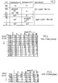
- a “duty cycle tvh ” with the range 0 to 200 (see FIG. 3): In the range from 0 to 100, tvh directly sets the duty cycle (second duty cycle wg ) for the relief valve 20. In the range between 100 to 200, the duty cycle (first duty ratio tzv) for the switching valve 19 results from tvh by subtraction of 100.
- the relief valve is fully controlled in this area, that is to say.
- the duty cycle precontrol value tvhkf is determined via characteristic curves 41, 42 from the rotational speed nmot and the throttle valve angle dkwin.
- An example of a duty cycle pilot control map can be seen in FIG. 4.
- a further problem arises during the switching process due to the transition from high load to overrun operation (throttle valve 22 not activated): In the charge air line there is a high pressure for a short time upstream of the throttle valve 22 - there is the take-off point for the auxiliary pressure. If there is a duty cycle of 100 for speeds nmot below a speed limit for switching over to the two-charger mode, the turbine cut-in valve is suddenly pushed fully open, as a result of which the first exhaust gas turbocharger 12 quickly loses energy. The same applies above this speed limit, i. H. in two-charger operation; there a pulse duty factor tvhk 0 would mean that the relief valve 20 opens and thus valuable energy of both exhaust gas turbochargers is lost.
- the duty cycle pilot control map 41 according to FIG. 4 therefore has another special feature on:
- Each speed characteristic line nmot constant makes a steep jump in the duty cycle map value tvhk at the lower end of the value range of the throttle valve angle dkwin.
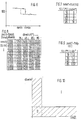
- the uncorrected duty cycle pilot control value tvhkf ' is finally subjected in the correction module 48 to a correction which is dependent on the charge air temperature tll and which reduces 56 the uncorrected pulse duty control pilot control value tvhkf by an amount tvhkf', which corresponds to a charge air temperature pilot control characteristic curve 57 according to FIG. 8. This results in the duty cycle pilot control value tvhkf.
- the control module 40 is composed of a proportional module 58, an integral module 59 and a differential module 60. However, the control component dtvh present at the output of the control module 40 is only active (switching module 61), provided the speed nmot and the throttle valve angle dkwin are simultaneously above the threshold values nreg and dkwreg relevant for the use of the control, see FIG. 10, unshaded area I. If at least one of the two parameters is below its relevant threshold value (hatched area 11), the calculation of the control component dtvh is omitted and this is set to zero.
- control component dtvh is calculated at fixed time intervals. This makes it possible to replace the temporal integral of the integral component 59 by a sum and the temporal differential of the differential component 60 by a difference.
- the integral component dtvhi (k) dtvhi (k-1). + Dp * rki is determined by summing the value of the I component dtvhi (k-1) calculated in the previous point in time (k-1) (in FIG. 2 symbolically represented by a storage element 66) is added 68 to the product dp * rki 67 from the integral parameter rki and the control difference dp.
- the integral parameter rki frki (nmot, dkwin) is determined from the integral parameter map 46 (see also FIG. 12).
- a switching module 69 maintains the old value dtvhi (k-1), which results in local stability of the I component and prevents it from "running away " is, for example, when the total value tvhrg is limited.
- the I component is subjected to a limitation 70, since the I component should influence the duty cycle only to a limited extent (for example
- less 30).
- the D component is only active (switching module 76) as long as the control difference dp is greater than a threshold value dpmin and the time change of the control difference ddp is greater than a threshold value ddpmin, otherwise the old value dtvhd (k-1) is retained.
- the contributions from P-58, I-59, and D component 60 are summed, 77, limited to a value of approximately 100 via a limiting module 78 and fed to the control module 49 via the switching module 61, provided the control component is active (FIG 10, operating point (nmot, dkwin) in area I.
- the switching module 61 also sets the output of the switching module 69 in the integral module 59 and the content of the memory element 73 to zero, provided the calculation of the control component is suppressed (FIG. 10, operating point (nmot, dkwin) in area 11).
- the module driver stage 52 now separates the sum signal from pilot control and regulation tvhrg into the individual control signals for the control valves 23, 24 of the cut-in valve 19 and blow-off valve 20 and converts them into duty cycle signals tzv and wg, which then - if necessary amplified - the control valves 23 and 24 are supplied. The separation takes place as already described above under FIG. 3.
- the merged boundary lines have been widened to form a hysteresis with npmax and fpmax (nmot) or npmin and fpmin (nmot) in order to avoid permanent switching on and off of the valve.
- the vent valve is therefore closed when the operating point (nmot, pist) is in area 111 (hatched from bottom left to top right) or, coming from area 111, in area IV (cross-hatched), and opened when the operating point lies in area V (hatched from top left to bottom right) or, coming from it, runs into area IV.
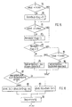
- 15 shows a flowchart for the switchover module 55 which controls the output of the uncorrected duty cycle pilot value tvhkf from the duty cycle pilot map 41 or duty cycle hysteresis map 42.
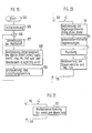
- Fig. 16 shows a flow chart for determination of the integral part. It is first checked whether one of the freezing conditions described above is fulfilled, 87. If no, a new value of the I component dtvhi (k) is calculated 88, if yes, the component dtvhi (k) is equal to that calculated in the previous program run Old value dtvhi (k-1) set, 89. This is followed by a limitation of the amount of the I component, 90.
- FIG. 18 it is also shown in FIG. 18 how the division of the duty cycle value from the control and regulation for controlling the activation valve or relief valve is separated.
- a first step it is first checked whether the total value from pilot control and regulation tvhrg is greater than 100, 97. If no, the connection valve is not activated (connection valve open), 98 and the duty cycle value tvh is set to tvhrg, 99.
- the duty cycle tvh 100 is limited, as described above.
- the control valve of the relief valve is clocked with the limited duty cycle wg.
- the blow-off valve is fully activated; that is, it is closed, 101 and the pulse duty factor tvh is determined from the difference between the total value from pilot control and regulation tvhrg and the value 100, 102.
- the pulse duty factor is again limited in accordance with the adjustable range, 103 and the control valve 23 of the connecting valve 19 clocked with the limited duty cycle tzv.
- characteristics, maps, limit and threshold values are not generally applicable, but are only given as an example for a specific internal combustion engine. However, they show a way of how they must look in principle and can be easily adapted to supercharged internal combustion engines or where the focal points of the optimization work are to be laid.
- the first interrupt program shown in FIG. 20 interrupts the main program 110. It is time-controlled and is processed approximately every 10 ms. It determines the control components (dtvhp, dtvhi (corresponding to FIG. 16) and dtvhd (corresponding to FIG. 17)), 111. The static and dynamic limits, 112 are then determined. Finally, the control signals 113 are rounded to the working range of the Control valves 23, 24 and their control 114 with the duty ratios wg and tzv according to FIG. 18 and the return 115 to the main program.
- the second interrupt program according to FIG. 21 is processed with a higher priority and interrupts both the main and the first interrupt program, 116.
- it is controlled in synchronism with the ignition, i. that is, it is called once per revolution of the internal combustion engine, for example by an engine management computer, which here also provides the measurement data for the measurement data acquisition 117 from nmot, pist, dkwin and tll.
- the measurement data acquisition 117 can of course also be carried out by the control unit 23 itself.
- the jump back to the interrupted program then takes place, 118.
Landscapes
- Engineering & Computer Science (AREA)
- Chemical & Material Sciences (AREA)
- Combustion & Propulsion (AREA)
- Mechanical Engineering (AREA)
- General Engineering & Computer Science (AREA)
- Supercharger (AREA)
Claims (37)
Applications Claiming Priority (2)
| Application Number | Priority Date | Filing Date | Title |
|---|---|---|---|
| DE3623540 | 1986-07-12 | ||
| DE3623540A DE3623540C1 (de) | 1986-07-12 | 1986-07-12 | Mehrzylinder-Brennkraftmaschine mit zwei Abgasturboladern |
Publications (2)
| Publication Number | Publication Date |
|---|---|
| EP0253075A1 EP0253075A1 (fr) | 1988-01-20 |
| EP0253075B1 true EP0253075B1 (fr) | 1990-03-07 |
Family
ID=6305030
Family Applications (1)
| Application Number | Title | Priority Date | Filing Date |
|---|---|---|---|
| EP87105927A Expired - Lifetime EP0253075B1 (fr) | 1986-07-12 | 1987-04-23 | Moteur à combustion interne multicylindre avec deux turbo-compresseurs de suralimentation des gaz d'échappement |
Country Status (5)
| Country | Link |
|---|---|
| US (1) | US4781027A (fr) |
| EP (1) | EP0253075B1 (fr) |
| JP (1) | JPS6325319A (fr) |
| DE (2) | DE3623540C1 (fr) |
| ES (1) | ES2014271B3 (fr) |
Families Citing this family (42)
| Publication number | Priority date | Publication date | Assignee | Title |
|---|---|---|---|---|
| US4848086A (en) * | 1986-11-19 | 1989-07-18 | Honda Giken Kogyo Kabushiki Kaisha | Boost pressure control method for a supercharged internal combustion engine |
| US4982567A (en) * | 1988-01-29 | 1991-01-08 | Mazda Motor Corporation | Air supply control systems for turbocharged internal combustion engines |
| DE68901795T2 (de) * | 1988-03-19 | 1993-01-21 | Mazda Motor | Zufuhrluftkontrollverfahren fuer brennkraftmaschinen. |
| DE68910158T2 (de) * | 1988-03-19 | 1994-02-17 | Mazda Motor | Lufteinlasssteuersystem für Brennkraftmaschinen. |
| DE3817246A1 (de) * | 1988-05-20 | 1989-11-23 | Audi Ag | Mehrzylinder-brennkraftmaschine |
| JP2533644B2 (ja) * | 1988-05-27 | 1996-09-11 | マツダ株式会社 | 車両の排気タ―ボ過給機付エンジン |
| JPH0647933B2 (ja) * | 1988-10-27 | 1994-06-22 | マツダ株式会社 | 過給機付エンジンの制御装置 |
| JPH0772496B2 (ja) * | 1989-08-31 | 1995-08-02 | マツダ株式会社 | ターボ過給機付エンジンの排気制御装置 |
| JPH081133B2 (ja) * | 1989-09-01 | 1996-01-10 | マツダ株式会社 | ターボ過給機付エンジンの過給圧制御装置 |
| US5081842A (en) * | 1989-10-23 | 1992-01-21 | Toyota Jidosha Kabushiki Kaisha | Internal combustion engine with a dual turbocharger system |
| US5168707A (en) * | 1989-11-21 | 1992-12-08 | Toyota Jidosha Kabushiki Kaisha | Internal combustion engine with a dual turbocharger system |
| US5186005A (en) * | 1990-03-09 | 1993-02-16 | Toyota Jidosha Kabushiki Kaisha | Internal combustion engine with a dual turbocharger system |
| JPH03271029A (ja) * | 1990-03-20 | 1991-12-03 | Mazda Motor Corp | 自動変速機を備えた過給機付エンジンの制御装置 |
| JP2765173B2 (ja) * | 1990-03-26 | 1998-06-11 | トヨタ自動車株式会社 | 過給機付エンジンの制御方法 |
| DE4024572C2 (de) * | 1990-08-02 | 1994-11-10 | Kloeckner Humboldt Deutz Ag | Registeraufladung für Brennkraftmaschinen in Nutzfahrzeugen |
| DE4101708C2 (de) * | 1991-01-22 | 1994-12-08 | Man Nutzfahrzeuge Ag | Brennkraftmaschine mit zweistufiger Ladeluftkühlung |
| US5154058A (en) * | 1991-06-11 | 1992-10-13 | Toyota Jidosha Kabushiki Kaisha | Internal combustion engine with a dual turbocharger system |
| US5277029A (en) * | 1991-06-18 | 1994-01-11 | Toyota Jidosha Kabushiki Kaisha | Internal combustion engine with a dual turbocharger system |
| US5289684A (en) * | 1991-08-02 | 1994-03-01 | Toyota Jidosha Kabushiki Kaisha | Charging pressure control apparatus for an internal combustion engine with a dual turbocharger system |
| US5313798A (en) * | 1991-08-02 | 1994-05-24 | Toyota Jidosha Kabushiki Kaisha | Charging control apparatus for an internal combustion engine with a dual turbocharger system |
| DE4219791C2 (de) * | 1992-06-17 | 2002-07-11 | Bosch Gmbh Robert | System zur Regelung der Aufladung einer Brennkraftmaschine |
| DE19712861A1 (de) * | 1997-03-27 | 1998-10-01 | Bosch Gmbh Robert | Verfahren zum Regeln der Aufladung einer Brennkraftmaschine |
| US6082975A (en) * | 1997-05-27 | 2000-07-04 | Lahens; Albert | Cold turbocharger consisting of a low mass turbine single disk unit |
| GB9800282D0 (en) * | 1998-01-08 | 1998-03-04 | Rolls Royce Cars Limited | Turbocharger system |
| DE19812843B4 (de) * | 1998-03-24 | 2006-07-06 | Robert Bosch Gmbh | Verfahren zur Ladedruckregelung einer Brennkraftmaschine |
| JP3721962B2 (ja) * | 1999-08-20 | 2005-11-30 | 日産自動車株式会社 | ターボ過給機の制御装置 |
| US6715289B2 (en) * | 2002-04-08 | 2004-04-06 | General Motors Corporation | Turbo-on-demand engine with cylinder deactivation |
| DE10361114A1 (de) * | 2003-12-22 | 2005-07-14 | Daimlerchrysler Ag | Ladedruckregelung |
| JP2006077586A (ja) * | 2004-09-07 | 2006-03-23 | Honda Motor Co Ltd | 気筒休止内燃機関 |
| EP1640594A1 (fr) * | 2004-09-22 | 2006-03-29 | Ford Global Technologies, LLC, A subsidary of Ford Motor Company | Moteur turbocompressé et méthode de modification de débit des gaz d'échappement recirculés dans un moteur turbocompressé. |
| DE102005024055A1 (de) * | 2005-05-25 | 2006-11-30 | Daimlerchrysler Ag | Einrichtung und Verfahren zur Regelung eines Abgasturboladersystems |
| DE102006032835B4 (de) * | 2006-07-14 | 2011-01-27 | Audi Ag | Verfahren und Vorrichtung zur Ladedruckregelung einer Brennkraftmaschine |
| US7640794B2 (en) * | 2007-09-06 | 2010-01-05 | Ford Global Technologies, Llc | Airflow balance for a twin turbocharged engine system |
| US8001782B2 (en) | 2007-09-26 | 2011-08-23 | Ford Global Technologies, Llc | Approach for identifying and responding to an unresponsive wastegate in a twin turbocharged engine |
| US8359858B2 (en) * | 2007-10-30 | 2013-01-29 | Ford Global Technologies, Llc | Twin turbocharged engine with reduced compressor imbalance and surge |
| US8000878B2 (en) * | 2008-05-15 | 2011-08-16 | Honeywell International Inc. | Parallel sequential turbocharger architecture using engine cylinder variable valve lift system |
| US8276378B2 (en) * | 2009-07-22 | 2012-10-02 | GM Global Technology Operations LLC | System and method for controlling a two-stage series sequential turbocharger using bypass valve leakage control |
| US9309803B2 (en) * | 2013-12-05 | 2016-04-12 | GM Global Technology Operations LLC | Turbocharger compressor temperature control systems and methods |
| US9303553B2 (en) * | 2013-12-05 | 2016-04-05 | GM Global Technology Operations LLC | Turbo speed control for mode transitions in a dual turbo system |
| US9677514B2 (en) * | 2014-09-08 | 2017-06-13 | GM Global Technology Operations LLC | Air induction system |
| JP6848840B2 (ja) * | 2017-11-30 | 2021-03-24 | トヨタ自動車株式会社 | ウェイストゲートバルブの制御装置 |
| CN115711173A (zh) * | 2022-10-11 | 2023-02-24 | 联合汽车电子有限公司 | 一种车辆增压控制方法、电子设备及可读存储介质 |
Family Cites Families (9)
| Publication number | Priority date | Publication date | Assignee | Title |
|---|---|---|---|---|
| DE3032218C2 (de) * | 1980-08-27 | 1982-06-16 | Audi Nsu Auto Union Ag, 7107 Neckarsulm | Kolbenbrennkraftmaschine mit einem Abgasturbolader |
| DE3046876C2 (de) * | 1980-12-12 | 1987-05-14 | Mtu Motoren- Und Turbinen-Union Friedrichshafen Gmbh, 7990 Friedrichshafen | Brennkraftmaschine mit Aufladung durch Abgasturbolader |
| DE3129686A1 (de) * | 1981-07-28 | 1983-02-17 | Robert Bosch Gmbh, 7000 Stuttgart | Einrichtung zum steuern des ladedrucks bei einer mit aufladung betriebenen brennkraftmaschine |
| DE3216707C2 (de) * | 1982-05-05 | 1986-08-14 | ANT Nachrichtentechnik GmbH, 7150 Backnang | Netzwerk mit vorwählbar nichtlinearem Zusammenhang zwischen Eingangs- und Ausgangsgröße |
| DE3303350C2 (de) * | 1983-02-02 | 1994-10-13 | Bosch Gmbh Robert | Steuervorrichtung für den Ladedruck einer Brennkraftmaschine mit Turbolader |
| JPS6081425A (ja) * | 1983-10-13 | 1985-05-09 | Honda Motor Co Ltd | タ−ボチヤ−ジヤ付内燃機関の過給圧制御装置 |
| DE3420015A1 (de) * | 1984-05-29 | 1985-12-05 | Dr.Ing.H.C. F. Porsche Ag, 7000 Stuttgart | Mehrzylinder-brennkraftmaschine mit zwei abgasturboladern |
| JPS6165021A (ja) * | 1984-09-05 | 1986-04-03 | Nissan Motor Co Ltd | ターボチャージャの過給圧制御装置 |
| DE3438175A1 (de) * | 1984-10-18 | 1986-04-24 | Robert Bosch Gmbh, 7000 Stuttgart | Einrichtung zur regelung des ladedrucks einer brennkraftmaschine |
-
1986
- 1986-07-12 DE DE3623540A patent/DE3623540C1/de not_active Expired
-
1987
- 1987-04-23 EP EP87105927A patent/EP0253075B1/fr not_active Expired - Lifetime
- 1987-04-23 ES ES87105927T patent/ES2014271B3/es not_active Expired - Lifetime
- 1987-04-23 DE DE8787105927T patent/DE3761838D1/de not_active Expired - Lifetime
- 1987-07-10 JP JP62171305A patent/JPS6325319A/ja active Pending
- 1987-07-13 US US07/072,755 patent/US4781027A/en not_active Expired - Fee Related
Also Published As
| Publication number | Publication date |
|---|---|
| ES2014271B3 (es) | 1990-07-01 |
| DE3761838D1 (de) | 1990-04-12 |
| EP0253075A1 (fr) | 1988-01-20 |
| US4781027A (en) | 1988-11-01 |
| JPS6325319A (ja) | 1988-02-02 |
| DE3623540C1 (de) | 1987-08-20 |
Similar Documents
| Publication | Publication Date | Title |
|---|---|---|
| EP0253075B1 (fr) | Moteur à combustion interne multicylindre avec deux turbo-compresseurs de suralimentation des gaz d'échappement | |
| EP1440231B1 (fr) | Procede et dispositif pour commander un compresseur actionne electriquement | |
| EP1427929B1 (fr) | Procede et dispositif pour actionner au moins un turbocompresseur de moteur a combustion interne | |
| DE3623541C2 (fr) | ||
| DE19924274B4 (de) | System und Verfahren zum Steuern eines Turboladers zur Maximierung der Leistung eines Verbrennungsmotors | |
| EP1179128B1 (fr) | Procede et dispositif pour reguler la pression de suralimentation d'un moteur a combustion interne | |
| DE10314583B4 (de) | Motor mit bedarfsabhängiger Turboladerzuschaltung und Zylinderabschaltung | |
| EP0923666B1 (fr) | Systeme de fonctionnement d'un moteur a combustion interne, en particulier d'un vehicule a moteur | |
| DE112013007145B4 (de) | Steuervorrichtung für mit Turbolader ausgerüstetem Verbrennungsmotor | |
| DE69832858T2 (de) | Verfahren und Vorrichtung für die Treibstoffeinspritzung bei einem Verbrennungsmotor | |
| DE112013007079B4 (de) | Steuervorrichtung für Verbrennungsmotor | |
| DE10320056B4 (de) | Verfahren und Vorrichtung zur Regelung des Ladedruckes einer Brennkraftmaschine | |
| DE10332231A1 (de) | Anordnung und Verfahren zur leistungsbasierten Leerlaufdrehzahlregelung | |
| DE112015004395T5 (de) | Steuervorrichtung für eine brennkraftmaschine | |
| DE10243268A1 (de) | Verfahren zum Regeln der Aufladung einer Brennkraftmaschine | |
| DE102005007352B4 (de) | Leerlaufdrehzahlsteuerungs- bzw. Regelungssystem und -Verfahren | |
| DE102004049688B4 (de) | Zylinderabschaltung auf Drehmomentbasis mit Unterdruckkorrektur | |
| DE102004005945B4 (de) | Verfahren und Vorrichtung zur Ladedruckregelung bei zweistufiger Abgasturboaufladung | |
| DE3886369T2 (de) | Druckkontrolle für Lader für Brennkraftmaschinen. | |
| EP0178485B1 (fr) | Dispositif de régulation de la pression de charge d'un moteur à combustion | |
| DE10302453A1 (de) | Verfahren und Vorrichtung zur Regelung des Ladedrucks eines Abgasturboladers | |
| EP1826378A2 (fr) | Procédé de fonctionnement pour moteur thermique, en particulier d'automobile | |
| DE102005023260A1 (de) | Verfahren zur Regelung eines Abgasturboladers | |
| EP1347158A1 (fr) | Système de charge avec assistance électrique pour un moteur à combustion interne et methode pour la régulation | |
| DE4228279A1 (de) | Verfahren und Vorrichtung zur Sollwertbildung für eine Saugrohrdruck- und/oder Ladedruckregelung einer Brennkraftmaschine |
Legal Events
| Date | Code | Title | Description |
|---|---|---|---|
| PUAI | Public reference made under article 153(3) epc to a published international application that has entered the european phase |
Free format text: ORIGINAL CODE: 0009012 |
|
| AK | Designated contracting states |
Kind code of ref document: A1 Designated state(s): DE ES FR GB IT NL SE |
|
| 17P | Request for examination filed |
Effective date: 19871205 |
|
| 17Q | First examination report despatched |
Effective date: 19880527 |
|
| GRAA | (expected) grant |
Free format text: ORIGINAL CODE: 0009210 |
|
| AK | Designated contracting states |
Kind code of ref document: B1 Designated state(s): DE ES FR GB IT NL SE |
|
| ITF | It: translation for a ep patent filed | ||
| REF | Corresponds to: |
Ref document number: 3761838 Country of ref document: DE Date of ref document: 19900412 |
|
| GBT | Gb: translation of ep patent filed (gb section 77(6)(a)/1977) | ||
| ET | Fr: translation filed | ||
| PLBE | No opposition filed within time limit |
Free format text: ORIGINAL CODE: 0009261 |
|
| STAA | Information on the status of an ep patent application or granted ep patent |
Free format text: STATUS: NO OPPOSITION FILED WITHIN TIME LIMIT |
|
| 26N | No opposition filed | ||
| ITTA | It: last paid annual fee | ||
| PGFP | Annual fee paid to national office [announced via postgrant information from national office to epo] |
Ref country code: SE Payment date: 19920325 Year of fee payment: 6 |
|
| PGFP | Annual fee paid to national office [announced via postgrant information from national office to epo] |
Ref country code: DE Payment date: 19920331 Year of fee payment: 6 |
|
| PGFP | Annual fee paid to national office [announced via postgrant information from national office to epo] |
Ref country code: GB Payment date: 19920410 Year of fee payment: 6 |
|
| PGFP | Annual fee paid to national office [announced via postgrant information from national office to epo] |
Ref country code: ES Payment date: 19920420 Year of fee payment: 6 |
|
| PGFP | Annual fee paid to national office [announced via postgrant information from national office to epo] |
Ref country code: NL Payment date: 19920430 Year of fee payment: 6 Ref country code: FR Payment date: 19920430 Year of fee payment: 6 |
|
| PG25 | Lapsed in a contracting state [announced via postgrant information from national office to epo] |
Ref country code: GB Effective date: 19930423 |
|
| PG25 | Lapsed in a contracting state [announced via postgrant information from national office to epo] |
Ref country code: SE Effective date: 19930424 Ref country code: ES Free format text: LAPSE BECAUSE OF NON-PAYMENT OF DUE FEES Effective date: 19930424 |
|
| PG25 | Lapsed in a contracting state [announced via postgrant information from national office to epo] |
Ref country code: NL Effective date: 19931101 |
|
| NLV4 | Nl: lapsed or anulled due to non-payment of the annual fee | ||
| GBPC | Gb: european patent ceased through non-payment of renewal fee |
Effective date: 19930423 |
|
| PG25 | Lapsed in a contracting state [announced via postgrant information from national office to epo] |
Ref country code: FR Effective date: 19931229 |
|
| PG25 | Lapsed in a contracting state [announced via postgrant information from national office to epo] |
Ref country code: DE Effective date: 19940101 |
|
| REG | Reference to a national code |
Ref country code: FR Ref legal event code: ST |
|
| EUG | Se: european patent has lapsed |
Ref document number: 87105927.5 Effective date: 19931110 |
|
| REG | Reference to a national code |
Ref country code: ES Ref legal event code: FD2A Effective date: 19990301 |
|
| PG25 | Lapsed in a contracting state [announced via postgrant information from national office to epo] |
Ref country code: IT Free format text: LAPSE BECAUSE OF NON-PAYMENT OF DUE FEES;WARNING: LAPSES OF ITALIAN PATENTS WITH EFFECTIVE DATE BEFORE 2007 MAY HAVE OCCURRED AT ANY TIME BEFORE 2007. THE CORRECT EFFECTIVE DATE MAY BE DIFFERENT FROM THE ONE RECORDED. Effective date: 20050423 |