EP0253111A1 - Procédé et installation de traitement d'un tissu tubulaire en déplacement à l'état humide - Google Patents
Procédé et installation de traitement d'un tissu tubulaire en déplacement à l'état humide Download PDFInfo
- Publication number
- EP0253111A1 EP0253111A1 EP87107765A EP87107765A EP0253111A1 EP 0253111 A1 EP0253111 A1 EP 0253111A1 EP 87107765 A EP87107765 A EP 87107765A EP 87107765 A EP87107765 A EP 87107765A EP 0253111 A1 EP0253111 A1 EP 0253111A1
- Authority
- EP
- European Patent Office
- Prior art keywords
- tubular
- goods
- expansion zone
- wet
- width
- Prior art date
- Legal status (The legal status is an assumption and is not a legal conclusion. Google has not performed a legal analysis and makes no representation as to the accuracy of the status listed.)
- Granted
Links
- 239000004744 fabric Substances 0.000 title claims abstract description 42
- 238000000034 method Methods 0.000 title claims abstract description 21
- 238000012937 correction Methods 0.000 claims abstract description 13
- 238000007789 sealing Methods 0.000 claims abstract description 9
- 238000002347 injection Methods 0.000 claims abstract description 6
- 239000007924 injection Substances 0.000 claims abstract description 6
- 239000000126 substance Substances 0.000 claims description 13
- 239000007921 spray Substances 0.000 claims description 11
- 230000001105 regulatory effect Effects 0.000 claims description 6
- 230000007704 transition Effects 0.000 claims description 3
- 239000003795 chemical substances by application Substances 0.000 claims 1
- 238000005507 spraying Methods 0.000 claims 1
- 239000004014 plasticizer Substances 0.000 description 7
- 238000013461 design Methods 0.000 description 6
- 239000007788 liquid Substances 0.000 description 4
- 239000000463 material Substances 0.000 description 3
- 238000007664 blowing Methods 0.000 description 2
- 230000002411 adverse Effects 0.000 description 1
- 238000010276 construction Methods 0.000 description 1
- 238000010924 continuous production Methods 0.000 description 1
- 230000001276 controlling effect Effects 0.000 description 1
- 238000010586 diagram Methods 0.000 description 1
- 238000002474 experimental method Methods 0.000 description 1
- 230000002349 favourable effect Effects 0.000 description 1
- 239000000835 fiber Substances 0.000 description 1
- 238000005470 impregnation Methods 0.000 description 1
- 239000011148 porous material Substances 0.000 description 1
- 230000000717 retained effect Effects 0.000 description 1
- 238000012360 testing method Methods 0.000 description 1
- 238000005406 washing Methods 0.000 description 1
Images

Classifications
-
- D—TEXTILES; PAPER
- D06—TREATMENT OF TEXTILES OR THE LIKE; LAUNDERING; FLEXIBLE MATERIALS NOT OTHERWISE PROVIDED FOR
- D06C—FINISHING, DRESSING, TENTERING OR STRETCHING TEXTILE FABRICS
- D06C5/00—Shaping or stretching of tubular fabrics upon cores or internal frames
Definitions
- the invention relates to a method for treating continuously transported tubular goods in the wet state, according to the preamble of claim 1. Furthermore, the invention relates to an apparatus for performing this method.
- a method and an apparatus of the kind described are known from DE-A-34 33 701.
- an expansion zone is sealed at its beginning and end by a pair of rollers, one roller of which can be driven and regulated.
- the feed speed and / or the take-off speed of the tubular goods are regulated via the speed of the driven rollers.
- a very uniform stretching of the tubular fabric is achieved in the manner described above without the surface being adversely affected (by mechanical devices).
- the object of the present invention is to provide a further method of the type required in the preamble of claim 1, which is at is also characterized by very uniform stretching and gentle handling of the tubular goods in that it enables a particularly space-saving and structurally simple design of the device used for its implementation.
- the tubular fabric immediately stretches to the last stage of a wet treatment, that is to say the stretch zone with the balloon-like inflation of the tubular fabric is arranged here, there is first of all a considerable saving of space compared to a separate expansion zone.
- This and the structurally relatively simple construction of the associated device are further favored by the fact that the wet tubular goods from the last wet treatment stage are supplied in sufficient quantity to the beginning of the expansion zone, that the stock of goods which is always present there ensures sufficient sealing of the tubular goods against air leakage , whereby the tubular goods can be fed to the beginning of the expansion zone without tension and can also be removed from there without tension and fed to the actual expansion zone.
- the desired simplification is supported in an extremely advantageous manner that the the correction value determined during the actual value / setpoint comparison is used as a correction output signal in order to control the amount of air injection into the tubular fabric in the expansion zone in the sense of a width correction of this tubular fabric determined to be necessary.
- the stretch zone can thus be provided, for example, immediately after or above a last washing compartment, impregnation compartment or another wet treatment compartment, it also being advantageous to treat the goods in a tube-wide condition and thus at the beginning of the stretch zone feed.
- the tubular goods can be passed through a pinch joint at the end of the expansion zone in a manner known per se and be drained and laid flat in the process.
- the tubular goods can be dewatered not only continuously through a continuously working wet treatment plant and an expansion zone with width extension, but also continuously - without stopping the wet treatment plant - in the finished width.
- a device for carrying out the method according to the invention contains the features specified in the preamble of claim 3 and is characterized by the features specified in the characterizing part of this claim 3.
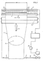
- the device for the wet treatment of continuously transported tubular goods 1 is arranged directly on the outlet part of a suitable wet treatment system, of which for the sake of simplicity only the last wet treatment compartment 2 is illustrated, which in the present case is in the form of a boot known per se is formed, but can also be formed in any other suitable manner if necessary.
- An expansion zone 3 of the treatment device according to the invention is provided directly above the lower boot end 2a of the wet treatment compartment 2 which is open at the top Explanatory nozzle device 4, compressed air is injected into the wet tubular fabric and this tubular fabric 1 can be inflated like a balloon - as indicated by the air bubble 5 - and thus can be deliberately overstretched.
- the essentially vertically oriented expansion zone 3 is sealed at the beginning and end, ie at the upper and lower ends, so that essentially no compressed air blown into the wet tubular fabric 1 can escape to the outside.
- the lower boot end 2a forming a transition area between the last wet treatment compartment 2 and the stretching zone 3 contains a sliding grid 6, which is preferably designed as a plastic sliding grate, which brings the wet tubular goods 1 free of tension and a goods store immediately below the stretching zone 3 forms, as indicated in Fig. 1 by the tubular fabric 1 pushed together in folds in the lower boot end 2a.
- This Goods store on the sliding grate 6 thereby simultaneously forms a lower sealing point at the lower end of the expansion zone 3 against air leakage from the tubular goods 1.
- the upper sealing point is formed by a pair of squeeze rollers 7, which is known per se.
- the nozzle device 4 provided for blowing compressed air into the tubular material 1 can in principle be designed and arranged in any suitable embodiment. It is particularly advantageous if - as shown in FIG. 1 - this nozzle device contains two swivel arms 8a and 8b arranged on both sides of the tubular fabric 1, at the free ends of which compressed air nozzles 9 are attached, between which the tubular fabric 1 is guided.
- the swivel arms 8a, 8b containing the supply air lines to the compressed air nozzles 9 are held in swivel bearings 10a and 10b, which are only indicated, so that the swivel arms 8a, 8b can move in the direction of the indicated double arrows 11, which on the one hand makes it easy Guidance of the inflated tubular goods 1 within the expansion zone 3 can be achieved without this other undesirable mechanical influence on the outside of the tubular goods 1 (chafing points) can occur.
- the compressed air nozzles 9 are connected to a compressed air supply line 12 in which a continuously regulating compressed air metering valve 13 is provided and which in turn is connected to a high-performance blower 14 belonging to the nozzle device 4.
- the compressed air metering valve 13 is assigned a motor with a control controller 15, the metering valve 13 of the nozzle device 4 being connected in terms of control to a computer 16 of a suitable design via this motor with the control controller 15.
- a width measuring device 17 is also connected in terms of control to this computer 16, which can be provided in any suitable embodiment.
- the computer 16 simultaneously connects the width measuring device 17 with the nozzle device 4 or its compressed air metering valve 13 in such a way that the compressed air supply to the nozzle device 4 can be controlled or readjusted as a function of a difference between the measured and predetermined width of the goods.
- width measuring device 17 Any mechanical, electromechanical or electronic device suitable for this purpose can be used as the width measuring device 17. However, it is particularly advantageous if this width measuring device is a photoelectronic measuring device 17 working with a light curtain.
- the treatment device according to the invention also contains an application spray device 19, directly in front of the pinch joint or the pinch roller pair 7 that forms it, by means of which suitable chemicals, for example plasticizers, can be sprayed onto the wet tube material 1 before the tube material the pinch roller pair 7 happens.
- This application spray device 19 contains two spray tubes 20 arranged on both sides of the tubular goods 1 and a circulation pump 21, which is connected on the one hand via a pressure line 22 to the spray tubes 20 and on the other hand via its suction line 23 to a fleet collecting device 24 below the wet treatment compartment 2.
- An application medium metering device 25 of a suitable design is also connected to the suction line 23 of this circulation pump 21 via a metering line 26.
- two can also be provided at a suitable distance from one another on the outside of the inflated tubular fabric 1, guide rods or guide rollers 27 acting in such a way that the tubular fabric 1 approaching the squeeze rollers 7 have already been compressed to a certain extent and aligned in width in order to enable the pair of squeeze rollers 7 to pass without creases.
- the design and arrangement of the treatment device described so far with reference to the example according to FIG. 1 is extremely space-saving but is simply constructed and easily accessible everywhere.
- the device also represents an extremely favorable combination of three essential treatment processes: the main type of treatment, namely the wet overstretching and stretching of the wet tubular goods, can be carried out in an extremely advantageous manner with the dewatering of the tubular goods (by means of the upper pair of nip rollers 7) and with the Application of additional chemicals (eg plasticizers or the like) can be combined in the area in front of the nip rollers.
- additional chemicals eg plasticizers or the like
- a suitable converter can be used for controlling the motor 15 of the compressed air metering valve 13 instead of the positioner mentioned, for example a so-called IP converter, by means of which the electrical or electronic control signals coming from the computer 16 are converted into pneumatic control variables. to control the drive of the compressed air metering valve 13 in the sense of opening or closing or throttling this valve.
- the tubular fabric 1 is transported continuously at a predetermined speed in the direction of arrow 1a through the expansion zone 3 through the pair of squeeze rollers 7 and finally through the width measuring device 17.
- the tubular fabric 1 is, for example, circular knitted tubular fabric which is to be specifically stretched or stretched to a predetermined width (in the folded-up state again).
- the tubular goods 1 at the beginning and end of the expansion zone 3 is sealed against air leakage, with the help of the air bubble 5 which is constantly maintained within the hose by compressed air injection, overexpanded in the wet state (tests have shown that wet hose goods can be overstretched with air up to about 30% of their width).
- the wet tubular fabric 1 passes through the pinch joint formed by the pair of squeeze rollers 7, is retained by the air bubble 5 and the tubular fabric 1 is mechanically dewatered. At the same time, the tubular goods 1 are laid completely wrinkle-free in this pinch joint.
- the squeezed-out and downward-flowing liquid seals off the goods balloon formed in the expansion zone 3 (ie free spaces between the fibers are closed by the liquid) and thus allows the tubular goods 1 to be overstretched only at the points at which compressed air is supplied via the compressed air nozzles 9 is injected into the interior of the tubular fabric 1, the liquid is displaced by air.
- the tubular fabric 1 In the extended state, ie in its full width WB achieved by overstretching, the tubular fabric 1 then passes through the width measuring device 17.
- the actual width achieved or the actual value obtained is measured electronically with the aid of a light curtain indicated by arrows 18 .
- the actual value of the fabric width WB measured in the width measuring device 17 is fed to the computer 16, into which a desired value, ie the desired fabric width, is entered.
- the actual value and the target value are then compared in the computer 16. If a deviation between the actual value and the target value is ascertained in the computer 16, ie if, for example, the actual value is 500 mm and the predetermined target value is 600 mm, then a corresponding correction value is formed, which is converted in the computer into a correction output signal.
- This correction output signal is fed to a positioner 29 of the motor 15 assigned to the compressed air metering valve 13 or a suitable converter (for example a so-called IP converter), so that the amount of air injection (via the compressed air nozzles 9) into the tubular fabric 1 in In terms of the required width correction of these tubular goods 1 can be controlled or readjusted. If, for example, the actual value of the fabric widths WB behind the expansion zone 3 is determined to be too small, then the amount of compressed air to be introduced into the tubular fabric 1 via the compressed air nozzles 9 must be increased accordingly in order to bring about a greater overstretching of the tubular fabric 1 in the expansion zone 3, and vice versa.
- a suitable converter for example a so-called IP converter
- plasticizer or another chemical is also to be applied during this overstretching of the wet tubular fabric 1 before dewatering (pinch roller pair 7), this can be done in the manner described above with reference to FIG. 1 with the aid of the application spray device 19.
- Plasticizers can be used, for example, in the order of about 1-2% of the weight of the goods.
- These application chemicals are expediently metered into the suction line 23 of the circulating pump 21 (see FIG. 1), so that the resulting liquor with the help of the spray pipes 20 on both sides or on all sides directly in front of the pinch joint (pinch roller pair 7) on the outside of the Tubular goods can be applied.
Landscapes
- Engineering & Computer Science (AREA)
- Textile Engineering (AREA)
- Treatment Of Fiber Materials (AREA)
Applications Claiming Priority (2)
| Application Number | Priority Date | Filing Date | Title |
|---|---|---|---|
| DE3624406 | 1986-07-18 | ||
| DE19863624406 DE3624406A1 (de) | 1986-07-18 | 1986-07-18 | Verfahren und vorrichtung zur behandlung von kontinuierlich transportierter schlauchware im nassen zustand |
Publications (2)
| Publication Number | Publication Date |
|---|---|
| EP0253111A1 true EP0253111A1 (fr) | 1988-01-20 |
| EP0253111B1 EP0253111B1 (fr) | 1989-10-25 |
Family
ID=6305519
Family Applications (1)
| Application Number | Title | Priority Date | Filing Date |
|---|---|---|---|
| EP87107765A Expired EP0253111B1 (fr) | 1986-07-18 | 1987-05-27 | Procédé et installation de traitement d'un tissu tubulaire en déplacement à l'état humide |
Country Status (5)
| Country | Link |
|---|---|
| US (1) | US4835992A (fr) |
| EP (1) | EP0253111B1 (fr) |
| JP (1) | JPS6328966A (fr) |
| DE (2) | DE3624406A1 (fr) |
| GR (1) | GR3000280T3 (fr) |
Families Citing this family (6)
| Publication number | Priority date | Publication date | Assignee | Title |
|---|---|---|---|---|
| SE8800609D0 (sv) * | 1988-02-19 | 1988-02-19 | Iro Ab | Anordning for hydro-extraktion av slangvara |
| DE59107257D1 (de) * | 1991-09-23 | 1996-02-22 | Solipat Ag | Verfahren zur Nassbehandlung textiler Schlauchware und Vorrichtung zur Durchführung des Verfahrens |
| US5826289A (en) * | 1996-09-27 | 1998-10-27 | Catallo; Frank | Wet processing system for treating wetted roped knitted fabric tubes |
| WO2005052241A1 (fr) * | 2003-11-17 | 2005-06-09 | Suchy Textilmaschinenbau Gmbh | Procede et dispositif pour traiter des materiaux textiles tubulaires, en particulier des tricots circulaires |
| US9416474B2 (en) * | 2013-04-12 | 2016-08-16 | Teresa Catallo | Washer for tubular knitted fabric material |
| US10570542B2 (en) * | 2015-09-11 | 2020-02-25 | Teresa Catallo | Apparatus and method for pre-shrinking a wet fabric prior to drying |
Citations (4)
| Publication number | Priority date | Publication date | Assignee | Title |
|---|---|---|---|---|
| CH625001A5 (en) * | 1976-08-11 | 1981-08-31 | Fulvio Conti | Apparatus for the wet treatment of tubular textile material. |
| DE3024252A1 (de) * | 1980-06-27 | 1982-01-21 | Maschinenfabrik Benninger AG, 9240 Uzwil | Einrichtung zur verweilbehandlung von textilbahnen |
| DE3425877A1 (de) * | 1984-07-13 | 1986-01-16 | Brückner-Apparatebau GmbH, 6120 Erbach | Verfahren zur kontinuierlichen nassveredelung von schlauchware |
| EP0174488A1 (fr) * | 1984-09-13 | 1986-03-19 | Brückner Apparatebau GmbH | Procédé et installation pour étirer des articles tubulaires |
Family Cites Families (13)
| Publication number | Priority date | Publication date | Assignee | Title |
|---|---|---|---|---|
| DE1704521C2 (de) * | 1967-02-10 | 1982-04-22 | Bemberg Folien Gmbh, 5600 Wuppertal | Vorrichtung zum biaxialen Verstrecken eines Schlauches aus thermoplastischem Kunststoff |
| SE309018B (fr) * | 1967-05-10 | 1969-03-10 | Nyman C | |
| US3580015A (en) * | 1968-09-06 | 1971-05-25 | Fukui Seiren Kako Keya Kk | Device for treating textile fabric |
| GB1230477A (fr) * | 1968-11-20 | 1971-05-05 | ||
| US3631692A (en) * | 1969-03-26 | 1972-01-04 | Rimar Spa | Machine for washing fabrics |
| JPS4840855A (fr) * | 1971-09-23 | 1973-06-15 | ||
| JPS5117636B2 (fr) * | 1971-12-29 | 1976-06-03 | ||
| JPS4961494A (fr) * | 1972-10-13 | 1974-06-14 | ||
| JPS5212832B2 (fr) * | 1972-12-28 | 1977-04-09 | ||
| DE2539350C2 (de) * | 1975-09-04 | 1977-09-01 | Hoechst Ag, 6000 Frankfurt | Verfahren zum kontinuierlichen Färben von Cellulosefasern oder deren Mischungen mit Synthesefasern mit auf der Faser erzeugten wasserunlöslichen Azofarbstoffen |
| US4376621A (en) * | 1977-03-31 | 1983-03-15 | The Dow Chemical Company | Method and apparatus for tube extrusion |
| JPS56107061A (en) * | 1980-01-23 | 1981-08-25 | Santo Tekkosho Kk | Set method and apparatus of circular knitted fabric |
| DD214157A1 (de) * | 1983-03-11 | 1984-10-03 | Fuerstenwalde Reifen Veb K | Breitenmesseinrichtung fuer bewegte materialbahnen, insbesondere an gewebekalandern |
-
1986
- 1986-07-18 DE DE19863624406 patent/DE3624406A1/de not_active Withdrawn
-
1987
- 1987-05-27 EP EP87107765A patent/EP0253111B1/fr not_active Expired
- 1987-05-27 DE DE8787107765T patent/DE3760880D1/de not_active Expired
- 1987-07-10 US US07/072,349 patent/US4835992A/en not_active Expired - Fee Related
- 1987-07-14 JP JP62175781A patent/JPS6328966A/ja active Pending
-
1990
- 1990-01-22 GR GR89400256T patent/GR3000280T3/el unknown
Patent Citations (4)
| Publication number | Priority date | Publication date | Assignee | Title |
|---|---|---|---|---|
| CH625001A5 (en) * | 1976-08-11 | 1981-08-31 | Fulvio Conti | Apparatus for the wet treatment of tubular textile material. |
| DE3024252A1 (de) * | 1980-06-27 | 1982-01-21 | Maschinenfabrik Benninger AG, 9240 Uzwil | Einrichtung zur verweilbehandlung von textilbahnen |
| DE3425877A1 (de) * | 1984-07-13 | 1986-01-16 | Brückner-Apparatebau GmbH, 6120 Erbach | Verfahren zur kontinuierlichen nassveredelung von schlauchware |
| EP0174488A1 (fr) * | 1984-09-13 | 1986-03-19 | Brückner Apparatebau GmbH | Procédé et installation pour étirer des articles tubulaires |
Also Published As
| Publication number | Publication date |
|---|---|
| DE3624406A1 (de) | 1988-01-28 |
| JPS6328966A (ja) | 1988-02-06 |
| GR3000280T3 (en) | 1991-03-15 |
| DE3760880D1 (en) | 1989-11-30 |
| EP0253111B1 (fr) | 1989-10-25 |
| US4835992A (en) | 1989-06-06 |
Similar Documents
| Publication | Publication Date | Title |
|---|---|---|
| DE719074C (de) | Verfahren zur Herstellung von kuenstlich geformten Gebilden aus tierischen Elastin- und bzw. oder Kollagenfasern oder solche Fasern enthaltenden Stoffen | |
| EP0887460B1 (fr) | Procédé et appareil pour nettoyer une bande de transport | |
| EP0174488B1 (fr) | Procédé et installation pour étirer des articles tubulaires | |
| DE602005006290T2 (de) | Maschine und verfahren zur behandlung von sowohl breitmaschigem als auch strangförmigem stoff | |
| EP0253111B1 (fr) | Procédé et installation de traitement d'un tissu tubulaire en déplacement à l'état humide | |
| DE2817487A1 (de) | Verfahren zum einziehen eines fadens in eine texturierduese und vorrichtung zur durchfuehrung des verfahrens | |
| DE2102406C2 (de) | Verfahren und Vorrichtung zur Verminderung des Feuchtigkeitsgehaltes bzw. zum Trocknen eines Textilfadens | |
| EP3266932A1 (fr) | Dispositif de nettoyage d'un feutre dans une installation de fabrication d'une bande de papier | |
| EP0967317B1 (fr) | Procédé pour l'encollage des bords et rameuse avec un dispositif pour l'encollage des bords | |
| DE578482C (de) | Sauglufttrockenmaschine zum Trocknen von Stoffbahnen | |
| EP2222911A1 (fr) | Procédé de coloration d'un tuyau flexible en matériau textile et machine de coloration pour la réalisation du procédé | |
| DE1635009A1 (de) | Verfahren und Vorrichtung zum Staerken und Trocknen der Ketten von synthetischen Garnen | |
| DD206507A3 (de) | Einrichtung zum glaetten und trocknen feuchter waesche | |
| DE3127916C2 (fr) | ||
| EP0075073A1 (fr) | Procédé et appareil de traitement au mouillé de matières textiles | |
| DE3926963C1 (fr) | ||
| DE2502146A1 (de) | Vorrichtung zum waschen oder dergl. behandeln von langgestrecktem material, insbesondere textilbahnen, -straengen oder dergl. | |
| DE2109009A1 (de) | Vorrichtung zur Naßbehandlung einer Textilbahn | |
| EP0825290B1 (fr) | Elargisseur pour tissus humides | |
| EP0389674A2 (fr) | Bande de pressage pour une installation de pressage | |
| DE1760268C3 (de) | Verfahren und Vorrichtung zum Aufnehmen von Gewebeschläuchen aus einem Zurichtungsbad | |
| DE2823530A1 (de) | Verfahren und vorrichtung zum nassbehandeln einer warenbahn | |
| DE2036430C3 (de) | Verfahren zum Behandeln insbesondere langfloriger Polgewebe und Einrichtung zum Durchführen dieses Verfahrens. Zusatz lu·. 1635206 | |
| AT281401B (de) | Vorrichtung zum Waschen eines Bandes | |
| DE19536355A1 (de) | Verfahren und Vorrichtung zum kontinuierlichen Behandeln einer Warenbahn |
Legal Events
| Date | Code | Title | Description |
|---|---|---|---|
| PUAI | Public reference made under article 153(3) epc to a published international application that has entered the european phase |
Free format text: ORIGINAL CODE: 0009012 |
|
| AK | Designated contracting states |
Kind code of ref document: A1 Designated state(s): CH DE FR GR IT LI SE |
|
| 17P | Request for examination filed |
Effective date: 19880311 |
|
| 17Q | First examination report despatched |
Effective date: 19890323 |
|
| GRAA | (expected) grant |
Free format text: ORIGINAL CODE: 0009210 |
|
| ITF | It: translation for a ep patent filed | ||
| AK | Designated contracting states |
Kind code of ref document: B1 Designated state(s): CH DE FR GR IT LI SE |
|
| REF | Corresponds to: |
Ref document number: 3760880 Country of ref document: DE Date of ref document: 19891130 |
|
| ET | Fr: translation filed | ||
| REG | Reference to a national code |
Ref country code: GR Ref legal event code: FG4A Free format text: 3000280 |
|
| PLBE | No opposition filed within time limit |
Free format text: ORIGINAL CODE: 0009261 |
|
| STAA | Information on the status of an ep patent application or granted ep patent |
Free format text: STATUS: NO OPPOSITION FILED WITHIN TIME LIMIT |
|
| 26N | No opposition filed | ||
| ITTA | It: last paid annual fee | ||
| EAL | Se: european patent in force in sweden |
Ref document number: 87107765.7 |
|
| PGFP | Annual fee paid to national office [announced via postgrant information from national office to epo] |
Ref country code: FR Payment date: 19970411 Year of fee payment: 11 |
|
| PGFP | Annual fee paid to national office [announced via postgrant information from national office to epo] |
Ref country code: SE Payment date: 19970416 Year of fee payment: 11 |
|
| PGFP | Annual fee paid to national office [announced via postgrant information from national office to epo] |
Ref country code: GR Payment date: 19970430 Year of fee payment: 11 |
|
| PG25 | Lapsed in a contracting state [announced via postgrant information from national office to epo] |
Ref country code: SE Free format text: LAPSE BECAUSE OF NON-PAYMENT OF DUE FEES Effective date: 19980528 |
|
| PG25 | Lapsed in a contracting state [announced via postgrant information from national office to epo] |
Ref country code: GR Free format text: LAPSE BECAUSE OF NON-PAYMENT OF DUE FEES Effective date: 19980531 Ref country code: FR Free format text: LAPSE BECAUSE OF NON-PAYMENT OF DUE FEES Effective date: 19980531 |
|
| EUG | Se: european patent has lapsed |
Ref document number: 87107765.7 |
|
| REG | Reference to a national code |
Ref country code: FR Ref legal event code: ST |
|
| PGFP | Annual fee paid to national office [announced via postgrant information from national office to epo] |
Ref country code: CH Payment date: 20020416 Year of fee payment: 16 |
|
| PGFP | Annual fee paid to national office [announced via postgrant information from national office to epo] |
Ref country code: DE Payment date: 20020730 Year of fee payment: 16 |
|
| PG25 | Lapsed in a contracting state [announced via postgrant information from national office to epo] |
Ref country code: LI Free format text: LAPSE BECAUSE OF NON-PAYMENT OF DUE FEES Effective date: 20030531 Ref country code: CH Free format text: LAPSE BECAUSE OF NON-PAYMENT OF DUE FEES Effective date: 20030531 |
|
| PG25 | Lapsed in a contracting state [announced via postgrant information from national office to epo] |
Ref country code: DE Free format text: LAPSE BECAUSE OF NON-PAYMENT OF DUE FEES Effective date: 20031202 |
|
| REG | Reference to a national code |
Ref country code: CH Ref legal event code: PL |
|
| PG25 | Lapsed in a contracting state [announced via postgrant information from national office to epo] |
Ref country code: IT Free format text: LAPSE BECAUSE OF NON-PAYMENT OF DUE FEES Effective date: 20050527 |