EP0253657A2 - Steuerungsverfahren von einem kontinuierlich veränderlichem Kraftfahrzeuggetriebe - Google Patents
Steuerungsverfahren von einem kontinuierlich veränderlichem Kraftfahrzeuggetriebe Download PDFInfo
- Publication number
- EP0253657A2 EP0253657A2 EP87306278A EP87306278A EP0253657A2 EP 0253657 A2 EP0253657 A2 EP 0253657A2 EP 87306278 A EP87306278 A EP 87306278A EP 87306278 A EP87306278 A EP 87306278A EP 0253657 A2 EP0253657 A2 EP 0253657A2
- Authority
- EP
- European Patent Office
- Prior art keywords
- spool
- transmission ratio
- engine
- gain
- engine speed
- Prior art date
- Legal status (The legal status is an assumption and is not a legal conclusion. Google has not performed a legal analysis and makes no representation as to the accuracy of the status listed.)
- Granted
Links
Images



Classifications
-
- F—MECHANICAL ENGINEERING; LIGHTING; HEATING; WEAPONS; BLASTING
- F16—ENGINEERING ELEMENTS AND UNITS; GENERAL MEASURES FOR PRODUCING AND MAINTAINING EFFECTIVE FUNCTIONING OF MACHINES OR INSTALLATIONS; THERMAL INSULATION IN GENERAL
- F16H—GEARING
- F16H61/00—Control functions within control units of change-speed- or reversing-gearings for conveying rotary motion ; Control of exclusively fluid gearing, friction gearing, gearings with endless flexible members or other particular types of gearing
- F16H61/38—Control of exclusively fluid gearing
- F16H61/40—Control of exclusively fluid gearing hydrostatic
- F16H61/46—Automatic regulation in accordance with output requirements
-
- B—PERFORMING OPERATIONS; TRANSPORTING
- B60—VEHICLES IN GENERAL
- B60W—CONJOINT CONTROL OF VEHICLE SUB-UNITS OF DIFFERENT TYPE OR DIFFERENT FUNCTION; CONTROL SYSTEMS SPECIALLY ADAPTED FOR HYBRID VEHICLES; ROAD VEHICLE DRIVE CONTROL SYSTEMS FOR PURPOSES NOT RELATED TO THE CONTROL OF A PARTICULAR SUB-UNIT
- B60W10/00—Conjoint control of vehicle sub-units of different type or different function
- B60W10/04—Conjoint control of vehicle sub-units of different type or different function including control of propulsion units
-
- B—PERFORMING OPERATIONS; TRANSPORTING
- B60—VEHICLES IN GENERAL
- B60W—CONJOINT CONTROL OF VEHICLE SUB-UNITS OF DIFFERENT TYPE OR DIFFERENT FUNCTION; CONTROL SYSTEMS SPECIALLY ADAPTED FOR HYBRID VEHICLES; ROAD VEHICLE DRIVE CONTROL SYSTEMS FOR PURPOSES NOT RELATED TO THE CONTROL OF A PARTICULAR SUB-UNIT
- B60W10/00—Conjoint control of vehicle sub-units of different type or different function
- B60W10/10—Conjoint control of vehicle sub-units of different type or different function including control of change-speed gearings
- B60W10/101—Infinitely variable gearings
- B60W10/103—Infinitely variable gearings of fluid type
-
- F—MECHANICAL ENGINEERING; LIGHTING; HEATING; WEAPONS; BLASTING
- F16—ENGINEERING ELEMENTS AND UNITS; GENERAL MEASURES FOR PRODUCING AND MAINTAINING EFFECTIVE FUNCTIONING OF MACHINES OR INSTALLATIONS; THERMAL INSULATION IN GENERAL
- F16H—GEARING
- F16H61/00—Control functions within control units of change-speed- or reversing-gearings for conveying rotary motion ; Control of exclusively fluid gearing, friction gearing, gearings with endless flexible members or other particular types of gearing
- F16H61/38—Control of exclusively fluid gearing
- F16H61/40—Control of exclusively fluid gearing hydrostatic
- F16H61/42—Control of exclusively fluid gearing hydrostatic involving adjustment of a pump or motor with adjustable output or capacity
- F16H61/421—Motor capacity control by electro-hydraulic control means, e.g. using solenoid valves
-
- F—MECHANICAL ENGINEERING; LIGHTING; HEATING; WEAPONS; BLASTING
- F16—ENGINEERING ELEMENTS AND UNITS; GENERAL MEASURES FOR PRODUCING AND MAINTAINING EFFECTIVE FUNCTIONING OF MACHINES OR INSTALLATIONS; THERMAL INSULATION IN GENERAL
- F16H—GEARING
- F16H61/00—Control functions within control units of change-speed- or reversing-gearings for conveying rotary motion ; Control of exclusively fluid gearing, friction gearing, gearings with endless flexible members or other particular types of gearing
- F16H61/38—Control of exclusively fluid gearing
- F16H61/40—Control of exclusively fluid gearing hydrostatic
- F16H61/42—Control of exclusively fluid gearing hydrostatic involving adjustment of a pump or motor with adjustable output or capacity
- F16H61/423—Motor capacity control by fluid pressure control means
-
- F—MECHANICAL ENGINEERING; LIGHTING; HEATING; WEAPONS; BLASTING
- F16—ENGINEERING ELEMENTS AND UNITS; GENERAL MEASURES FOR PRODUCING AND MAINTAINING EFFECTIVE FUNCTIONING OF MACHINES OR INSTALLATIONS; THERMAL INSULATION IN GENERAL
- F16H—GEARING
- F16H61/00—Control functions within control units of change-speed- or reversing-gearings for conveying rotary motion ; Control of exclusively fluid gearing, friction gearing, gearings with endless flexible members or other particular types of gearing
- F16H61/38—Control of exclusively fluid gearing
- F16H61/40—Control of exclusively fluid gearing hydrostatic
- F16H61/46—Automatic regulation in accordance with output requirements
- F16H61/465—Automatic regulation in accordance with output requirements for achieving a target input speed
Definitions
- the present invention relates to a method of controlling a continuously variable automotive transmission by controlling the transmission ratio based on the difference between a target rotational engine speed which is preset according to an indication of the driver's intention of acceleration or deceleration and a detected rotational engine speed.
- the rate of change di/dt of the transmission ratio i per unit time can be given by the equation (1): where Neo is the target rotational engine speed and Ne is the detected rotational engine speed and K is a gain.
- the detected rotational engine speed Ne is expressed by the following equation (2): where V is the speed of travel of the automobile or the output rotational ending speed, and C is a constant.
- a gain K is constant, and it can be understood from the equation (6) that dNe/dt is proportional to Ne, (Neo - Ne), 1/i.
- a method of controlling a continuously variable transmission in an automobile having an engine by controlling the transmission ratio thereof based on the difference between a target rotational speed of the engine which is preset according to an indication of the driver's intention of acceleration or deceleration and a detected rotational speed of the engine, the method comprising the step of reducing the gain of the rate of change of the transmission ratio as the detected rotational speed of the engine becomes higher.
- the rate of change of the detected engine speed may remain the same irrespective of whether the engine speed is high or low. Both stability and response are thus accomplished in the control of the transmission.
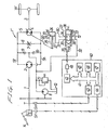
- FIG. 1 shows a first embodiment of the present invention.
- a hydraulically operated, continuously variable transmission T for use in an automobile includes a hydraulic pump 2 of the fixed displacement type having an input shaft 1 drivable by an automotive engine E, and a hydraulic motor 4 of the variable displacement type having a drive shaft 3 disposed coaxially with the hydraulic pump 2 for driving wheels W.
- the hydraulic pump 2 and the hydraulic motor 4 are interconnected by a closed hydraulic circuit 5.
- the closed hydraulic circuit 5 includes a higher-pressure oil passage 5h interconnecting the outlet port of the hydraulic pump and the inlet port of the hydraulic motor 4, and a lower-pressure oil passage 5f interconnecting the outlet port of the hydraulic motor 4 and the inlet port of the hydraulic pump 2.
- a bypass oil passage 6 is coupled between the outlet and inlet ports of the hydraulic pump 2, i.e., the higher-and lower-pressure oil passages 5h, 5f, in bypassing relation to the hydraulic motor 4.
- the bypass oil passage 6 has a clutch valve 7 serving as a clutch.
- a supply pump 8 which can be driven by the input shaft 1 through a gear train has an outlet port connected via check valves 9, 10 to the lower- and higher-pressure oil passages 5f, 5h for supplying working oil from an oil tank 12 to the closed hydraulic circuit 5 in order to compensate for a shortage of oil in the circuit 5.
- a relief valve 13 is connected between the outlet port of the supply pump 8 and the oil tank 12 for releasing an excessive oil pressure discharged by the supply pump 8.
- the opening of the clutch valve 7 is controlled by a control device (not shown). Power transmission between the input shaft 1 and the output shaft 3 can be controlled by the amount of opening of the clutch valve 7.
- the transmission ratio i of the continuously variable transmission T is controlled by continuously changing the displacement of the hydraulic motor 4 with respect to the fixed displacement of the hydraulic pump 2. If the displacement of the hydraulic motor 4 is increased, the transmission ratio i is also increased: If the displacement of the hydraulic motor 4 is reduced, the transmission ratio i is also reduced. Thus, the transmission ratio i between the rotational speed of the engine E and the rotational speed of the wheels W can be continuously varied.
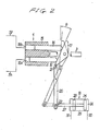
- the hydraulic motor 4 comprises a variable-displacement axial piston motor, for example.
- the hydraulic motor 4 includes a cylinder block 15 coupled to the output shaft 3 and a plurality of pistons 16 slidably fitted in the cylinder block 15 and angularly spaced in an annular pattern around the rotational axis of the output shaft 3.
- a swash plate 17 for limiting the reciprocating stroke of the pistons 16 is held against the tip ends of the pistons 16, the swash plate 17 being inclined at a variable angle 0.
- a cylinder chamber 18a defined in the cylinder block 15 and receiving one of the pistons 16 which is in an expanding stroke communicates with the higher-pressure oil passage 5h.
- a cylinder chamber 18b defined In the cylinder block 15 and receiving one of the pistons 16 which is in a contracting stroke communicates with the lower -pressure oil passage 5B.
- the hydraulic motor 4 of the above structure is known in the art.
- Higher-pressure oil discharged from the hydraulic pump 2 is delivered via the higher-pressure oil passage 5h into the cylinder chamber 18a, and lower-pressure oil discharged from the cylinder chamber 18b is returned via the lower-pressure oil passage 5£ back to the hydraulic pump 2.
- the cylinder block 15 and hence the output shaft 3 are rotated by reactive torque imposed by the swash plate 17 on the piston 16 in the expanding stroke.
- the displacement of the hydraulic motor 4 is determined by the stroke of the pistons 16.
- the transmission ratio i of the transmission T can continuously be varied from a minimum level to a maximum level by changing the angie 0 of the swash plate 17 from a maximum value (indicated by the solid lines) to a minimum value (indicated by the two-dot-and-dash lines).
- the transmission ratio i is given by the following equation:
- One end of the swash plate 17 is coupled by a pin 21 to one end of a swingable link 20, the other end of which is joined to a hydraulic cylinder assembly 19 by a pin 22 extending parallel to the pin 21.
- the cylinder assembly 19 comprises a cylinder 23, a piston 26 slidably fitted in the cylinder 23 and dividing the interior of the cylinder 23 into a head chamber 24 and a rod chamber 25, and a piston rod 27 integrally joined to the piston 26 and extending movably in a fluid-tight manner through the end of the cylinder 25 adjacent to the rod chamber 25.
- the distal end of the piston rod 27 is coupled to the other end of the swingable link 20 by the pin 22.
- the angle of the swash plate 17 is maximized to maximize the displacement of the hydraulic motor 4 for thereby increasing the transmission ratio i to a maximum.
- the swash plate angle is reduced to a minimum as indicated by the two-dot-and-dash lines, and so is the displacement of the hydraulic motor 4, minimizing the transmission ratio i.
- a solenoid-operated directional control valve 29 is connected between an oil passage 30 coupled to the head chamber 24 of the hydraulic cylinder assembly 19 and an oil passage 31 coupled to the rod chamber 25 of the hydraulic cylinder assembly 19, and an oil supply passage 32 coupled to the supply pump 8 and an oil release passage 33 coupled to the oil tank 12.
- the control valve 29 has ports 34, 35 communicating with the oil passages 30,31, respectively, and ports 36, 37 communicating with the oil supply and release passages 32, 33, respectively.
- the control valve also has a spool 38 switchingly movable between a lefthand position in which the ports 35, 37 communicate with each other and the ports 36, 34 communicate with each other, a neutral position in which the ports 36, 35 and the ports 34, 37 are disconnected from each other, and a righthand position in which the ports 36, 35 communicate with each other and the ports 34, 37 communicate with each other.
- the spool 38 as it moves between the above three positions has an intermediate position in which the degree of restriction is continuously variable.
- the spool 38 is moved according to a current a supplied to a solenoid 39.
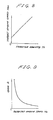
- the amount of working oil supplied to and discharged from the hydraulic cylinder assembly 19 via the directional control valve 29 is varied as shown in FIG. 3 dependent on the position of the spool 38. More specifically, when the current a is increased in a positive direction, the spool 38 is moved toward the righthand position for proportionally increasing the amount Q of working oil supplied to the rod chamber 25 of the hydraulic cylinder assembly 19. When the current a is increased in a negative direction, the spool 38 is moved toward the lefthand position for proportionally increasing the amount Q of working oil supplied to the head chamber 24 of the hydraulic cylinder assembly 19. In FIG.
- the amount Q of working oil supplied to the rod chamber 25, i.e., the amount Q of working oil discharged from the head chamber 24 is indicated on the positive side, whereas the amount Q of working oil discharged from the rod chamber 25, i.e., the amount Q of working oil supplied to the head chamber 24 is indicated on the negative side.
- the rate of change di/dt of the transmission ratio i based on changes in the amount Q of the working oil as shown in FIG. 3 is illustrated in FIG. 4.
- the solenoid 39 of the control valve 29 is controlled by a control circuit 40 comprising a digital-to-analog converter 42, an interface 43, an analog-to-digital converter 44, a central processing unit 45, a random-access memory 46, and a read-only memory 47 which are interconnected by an address data bus 41.
- the interface 43 is supplied with a pulse signal from an engine rotation sensor Sn which detects the rotational speed of the engine E, the pulse signal being indicative of the detected engine rotational speed.
- the analog-to-digital converter 44 is supplied with an analog signal from a throttle opening sensor St which detects the amount of opening of the throttle valve dependent on the depression of an accelerator pedal 14 which serves as an indication of the driver's intention of acceleration or deceleration, the analog signal being representative of the amount of opening of the throttle valve.
- the control circuit 40 also has an amplifier 48 connected between the digital-to-analog converter 42 and the solenoid 39.
- the amplifier 48 produces the current a proportional to an input voltage e applied by the digital-to-analog converter 42 as shown in FIG. 5, the current a being supplied to the solenoid 39.
- FIG. 6 is a block diagram of a control system.
- the amount of opening Th of the throttle valve which has been detected by the throttle opening sensor St, is applied to a block 51 in which a target engine speed Neo is selected from a map based on the applied amount of opening Th of the throttle valve.
- the difference (Neo - Ne) between the target engine speed Neo and a detected engine speed Ne is obtained at an adding point 54.
- the difference (Neo - Ne) is amplified to an output voltage e with a gain k by a next block 52.
- the output voltage e is employed to control the continuously variable transmission T through the amplifier 48, the control valve 29, and the cylinder assembly 19.
- the engine speed Ne dependent on the transmission ratio i determined by the transmission T is fed back from a feedback point 53 to the adding point 54.
- FIG. 7 is a flowchart of a control sequence executed by the control diagram of FIG. 6.
- the amount of opening Th of the throttle valve is read in a first step S1, followed by a second step S2 in which the target engine speed Neo corresponding to the amount of throttle valve opening Th is retrieved from the map.
- the detected engine speed Ne is read.
- FIGS. 10 and 11 illustrate a second embodiment of the present invention.
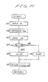
- FiG. 10 shows a control sequence including first through third steps m1 - m3 which are the same as the first through third steps S1 - S3 of FIG. 7 according to the first embodiment.
- a fourth step m4 ascertains whether or not the detected engine speed N3 is equal to or higher than a preset value Ne'.
- the hydraulic cylinder assembly 19 may be replaced with an electric actuator such as a step motor, a linear step motor, a DC motor, an AC motor, or the like, dependent on the arrangement of the control circuit 40.
- an electric actuator such as a step motor, a linear step motor, a DC motor, an AC motor, or the like, dependent on the arrangement of the control circuit 40.
- hydraulic and mechanical arrangements may be utilized to control the transmission, as described below.
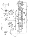
- FIGS. 12 and 13 show a third embodiment of the present invention.
- a control valve 60 is connected between the oil passages 30, 31 communicating respectively with the head and rod chambers 24, 25 of the hydraulic cylinder 19, and the oil supply passage 32 communicating with the supply pump 8 and the oil release passage 33 communicating with the oil tank 12.
- the control valve 60 includes a cylinder 61 having ports 62,63 communicating with the oil passages 30, 31, a port 64 communicating with the oil supply passage 32, and ports 65, 66 communicating with the oil tank 12 via the oil release passage 33, and a spool 67 movably fitted in the cylinder 61 for selectively establishing and shutting off fluid communication between these ports 62 -66.
- the spool 67 as it moves has an intermediate position in which the degree of restriction is continuously variable.
- the ports 62 through 66 are held out of communication with each other.
- the ports 64, 63 are brought into mutual communication and so are the ports 62, 65.
- the ports 63,66 are brought into mutual communication and so are the ports 62, 64.
- a bottomed cylindrical receiver member 68 is slidably fitted in the lefthand end of the cylinder 61. Between the lefthand end of the spool 67 and the receiver member 68, there is defined a spring chamber 69 communicating with the oil tank 12 and accommodating a coil spring 90 acting between the spool 67 and the bottom of the receiver member 68.
- a presser 71 is held against the outer end surface of the receiver member 68 for pushing the receiver member 68 into the cylinder 61 as the accelerator pedal 14 is depressed, i.e., as the amount of throttle opening Th is increased.
- the spring 70 imposes a spring force F1 (FIGS.
- the cylinder 61 has a stopper 72 projecting inwardly from its inner peripheral surface for limiting movement of the receiver member 68 into the cylinder 61.
- a hydraulic pressure chamber 73 is defined between the righthand end of the spool 67 and the righthand end of the cylinder 61.
- the cylinder 61 has a port 74 communicating with the hydraulic pressure chamber 73 and connected through a pilot oil passage 75 to an output port 76 of a hydraulic governor G.
- the hydraulic governor G is operable in response to rotation of the input shaft 1 and has an input port 77 coupled to an oil passage 78 communicating with the supply pump 8.
- the output port 76 of the hydraulic governor G produces a hydraulic governor pressure Pg proportional to the rotational speed of the engine E, the governor pressure Pg being supplied to the hydraulic pressure chamber 73.
- a coupling rod 81 coaxially projects from the righthand end of the spool 67 and extends hermetically and axially movably through the righthand end wall of the cylinder 61.
- a hydraulic cylinder assembly 85 is disposed in coaxial relation to the control valve 60.
- the hydraulic cylinder assembly 85 includes a piston 83 slidably fitted in a cylinder 84, there being a coil spring 82 interposed between the piston 83 and the coupling rod 81.
- the piston 83 and the cylinder 84 define therebetween a hydraulic pressure chamber 86 communicating with the pilot oil passage 75 through a pilot oil passage 87.
- a stopper 88 projects Inwardly from the inner peripheral surface of the cylinder 84 for limiting movement of the piston 83 in a direction out of the cylinder 84.
- the control valve 60 is of a conventional nature, and hence the aforesaid control mode can readily be accomplished simply by adding the hydraulic cylinder assembly 85 to the control valve 60.
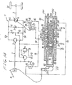
- FIG. 14 shows a fourth embodiment of the present invention.
- a control valve 90 is connected between the oil passages 30, 31 communicating respectively with the head and rod chambers 24, 25 of the hydraulic cylinder 19, and the oil supply passage 32 communicating with the supply pump 8 and the oil release passage 33 communicating with the oil tank 12.
- the control valve 90 includes a cylinder 96 having ports 91, 92 communicating with the oil passages 30,31, a port 93 communicating with the oil supply passage 32, and ports 94,95 communicating with the oil tank 12 via the oil release passage 33, a first spool 97 movably fitted in the cylinder 91, and a second spool 98 slidably fitted in the first spool 97.
- the first spool 97 is basically in the form of a bottomed hollow cylinder having two annular grooves 102, 103 defined in its outer peripheral surface substantially centrally in the axial direction, with an annular land 101 disposed axially between the annular grooves 102, 103.
- the land 101 is positioned substantially radially inwardly of the port 93, and the annular grooves 102, 103 are positioned substantially radially inwardly of the ports 91, 92, respectively.
- the land 101 has a pair of axially spaced oil passages 104, 105 defined radially therethrough and capable of communication with the port 93.
- the first spool 97 also includes an oil passage 106 opening into the annular groove 102 and an oil passage 107 opening into the annular groove 103, the oil passages 106, 107 opening into the interior space of the first spool 97.
- a closure member 108 is fitted in the open end of the first spool 97.
- the coil spring 70 is housed in the spring chamber 69 defined in the cylinder 96 between the closure member 108 and the receiver member 68 slidably fitted in the lefthand end of the cylinder 96.
- the presser 71 movable dependent on the depth to which the accelerator pedal 14 is depressed is held against the outer end surface of the member 68.
- the righthand end of the cylinder 96 and the closed end of the first spool 97 define therebetween a hydraulic pressure chamber 109 accommodating therein a coil spring 110.
- the spring chamber 69 is vented to atmosphere, and the hydraulic pressure chamber 109 is connected to the output port 76 of the hydraulic governor G through a port 111 defined in the cylinder 96 and the pilot oil passage 75.
- a control force F3 proportional to the amount of throttle opening Th is applied to the lefthand end of the first spool 97, and a control force F4 proportional to the engine speed Ne is imposed on the righthand end of the first spool 97.
- the control force F3 is produced by the spring load of the spring 70.
- the presser 71 moves the first spool 97 to the right to increase the control force F3.
- the presser 71 allows the first spool 97 to move to the left, reducing the control force F3.
- the piston 26 of the hydraulic cylinder assembly 19 is moved leftwardly thereby to reduce the displacement of the hydraulic motor 4 and hence lower the transmission ratio i. If F3 > F4, then the first spool 97 is moved to the right to bring the ports 92, 93 into mutual fluid communication and also bring the ports 91, 94 into mutual fluid communication. Therefore, the piston 26 of the hydraulic cylinder assembly 19 is moved rightwardly thereby to increase the displacement of the hydraulic motor 4 and hence increase the transmission ratio i.
- a spring chamber 115 is defined in the first spool 97 between the lefthand end of the second spool 98 and the closure member 108, the spring chamber 115 communicating with the spring chamber 69.
- the spring chamber 115 houses therein a coil spring 116 for normally urging the second spool 98 to move to the right.
- a hydraulic pressure chamber 117 is defined between the righthand end of the first spool 97 and the righthand end of the second spool 98. The hydraulic pressure chamber 117 is held in communication with the hydraulic pressure chamber 109 through a passage 118 defined axially in the righthand end of the first spool 97.
- the spring load of the spring 116 is applied to the lefthand end of the second spool 98, and a hydraulic force due to the hydraulic pressure Pg in the hydraulic pressure chamber 117 is applied leftwardly to the righthand end of the second spool 98.
- the second spool 98 has a pair of axially spaced annular grooves 120, 121 defined in its outer peripheral surface with an annular land 119 between the grooves 120,121.
- the inner ends of the oil passages 104,106 for interconnecting the ports 93, 91 and the inner ends of the oil passages 105, 107 for interconnecting the ports 93, 92 can be restricted by the second spool 98 as the annular grooves 120, 121 are moved relatively to these inner ends of the oil passages.
- the oil passages 104, 106; 105, 107 and annular grooves 120, 121 jointly constitute variable restriction mechanisms 122, 123, respectively, for continuously or steplessly adjusting the the amount of restricted opening between the oil passages 104, 106 and the oil passages 105, 107. Since the position of the second spool 98 with respect to the first spool 97 is determined by the engine speed Ne, the amount of the working oil supplied to and discharged from the hydraulic cylinder assembly 19 can be continuously adjusted by the variable restriction mechanisms 122, 123 dependent on the engine speed N3.
- variable restriction mechanisms 122, 123 are provided in passageways for supplying the working oil to the hydraulic cylinder assembly 19, such variable restriction mechanisms may instead be disposed in passages for relieving the working oil from the rod chamber 24 and the head chamber 25 of the hydraulic cylinder assembly 19' to the oil tank 12.
- the spring constant of the spring 116 may be reduced, so that when the force tending to move the second spool 98 is increased by an increase in the engine speed Ne, the second spool 98 may immediately be moved to the left to fully open the restricted opening between the oil passages 104, 106 and the oil passages 105,107 right away.
- substantially no intermediate opening position is available between the fully open position and the fully closed position for the second spool 98. The operation may then be substantially the same as that of the first embodiment.
- the present invention is not limited to the hydraulically operated, continuously variable automotive transmission, but may be applied to any of various other continuously variable transmissions such as of a belt drive or toroidal traction drive type.
- the present invention is not limited to the hydraulically operated, continuously variable automotive transmission comprising the fixed-displacement hydraulic pump 2 and the variable-displacement hydraulic motor.
- the principles of the present invention are applicable to a transmission comprising a variable-displacement hydraulic pump and a fixed-displacement hydraulic motor, or a transmission comprising a variable-displacement hydraulic pump and a variable-displacement hydraulic motor.
- the detection of the throttle valve opening or the accelerator pedal depression as an indication of the driver's intention of acceleration and deceleration may be replaced with the detection of the vacuum developed in the intake pipe of the engine, and the amount of fuel supplied.
- the engine speed may be calculated from the automobile speed or the output rotational speed and the transmission ratio.
- the gain of the rate of change of the transmission ratio is reduced as the detected engine speed is increased.
- the rate of change of the engine speed remains the same irrespective of whether the engine speed is high or low. Accordingly, both stability and response can be achieved in the control of the transmission.
Landscapes
- Engineering & Computer Science (AREA)
- General Engineering & Computer Science (AREA)
- Mechanical Engineering (AREA)
- Chemical & Material Sciences (AREA)
- Combustion & Propulsion (AREA)
- Transportation (AREA)
- Physics & Mathematics (AREA)
- Fluid Mechanics (AREA)
- Control Of Fluid Gearings (AREA)
- Control Of Transmission Device (AREA)
- Control Of Driving Devices And Active Controlling Of Vehicle (AREA)
Applications Claiming Priority (2)
| Application Number | Priority Date | Filing Date | Title |
|---|---|---|---|
| JP166325/86 | 1986-07-15 | ||
| JP61166325A JPH086797B2 (ja) | 1986-07-15 | 1986-07-15 | 車両用無段変速機の変速制御方法 |
Publications (3)
| Publication Number | Publication Date |
|---|---|
| EP0253657A2 true EP0253657A2 (de) | 1988-01-20 |
| EP0253657A3 EP0253657A3 (en) | 1989-04-26 |
| EP0253657B1 EP0253657B1 (de) | 1993-08-25 |
Family
ID=15829264
Family Applications (1)
| Application Number | Title | Priority Date | Filing Date |
|---|---|---|---|
| EP87306278A Expired - Lifetime EP0253657B1 (de) | 1986-07-15 | 1987-07-15 | Steuerungsverfahren von einem kontinuierlich veränderlichem Kraftfahrzeuggetriebe |
Country Status (4)
| Country | Link |
|---|---|
| US (1) | US4949596A (de) |
| EP (1) | EP0253657B1 (de) |
| JP (1) | JPH086797B2 (de) |
| DE (1) | DE3787133T2 (de) |
Cited By (9)
| Publication number | Priority date | Publication date | Assignee | Title |
|---|---|---|---|---|
| US4884475A (en) * | 1988-01-14 | 1989-12-05 | Hydromatik Gmbh | Automotive drive system for machines and vehicles |
| EP0317290A3 (de) * | 1987-11-16 | 1991-01-09 | Honda Giken Kogyo Kabushiki Kaisha | Steuerungsverfahren für das Übersetzungsverhältnis eines stufenlos verstellbaren Getriebes |
| EP0422821A1 (de) * | 1989-10-10 | 1991-04-17 | The Manitowoc Company, Inc. | Steuerungssystem und hydraulisches System für Kräne |
| FR2668516A1 (fr) * | 1990-10-31 | 1992-04-30 | Samsung Heavy Ind | Systeme de commande pour commander automatiquement des moyens d'actionnement d'une excavatrice. |
| US5218540A (en) * | 1989-03-22 | 1993-06-08 | Honda Giken Kogyo Kabushiki Kaisha | Method of controlling continuously variable transmission in combination with engine throttle control |
| US5297019A (en) * | 1989-10-10 | 1994-03-22 | The Manitowoc Company, Inc. | Control and hydraulic system for liftcrane |
| US5579931A (en) * | 1989-10-10 | 1996-12-03 | Manitowoc Engineering Company | Liftcrane with synchronous rope operation |
| WO2000051836A1 (de) * | 1999-03-01 | 2000-09-08 | Zf Friedrichshafen Ag | Antriebsstrangsteuerung |
| US6758356B1 (en) | 1989-10-10 | 2004-07-06 | Manitowoc Crane Companies, Inc. | Liftcrane with synchronous rope operation |
Families Citing this family (14)
| Publication number | Priority date | Publication date | Assignee | Title |
|---|---|---|---|---|
| US5166877A (en) * | 1987-10-02 | 1992-11-24 | Honda Giken Kogyo Kabushiki Kaisha | Method of speed reduction ratio control in continuously variable speed transmission |
| JP2882528B2 (ja) * | 1988-07-20 | 1999-04-12 | 本田技研工業株式会社 | 無段変速機のスロットル制御付き変速制御方法 |
| DE3934506C1 (de) * | 1989-10-16 | 1991-05-08 | Ford-Werke Ag, 5000 Koeln, De | |
| JPH03204440A (ja) * | 1989-12-29 | 1991-09-06 | Aisin Aw Co Ltd | 無段変速機の制御装置 |
| JP2848101B2 (ja) * | 1991-04-19 | 1999-01-20 | 三菱自動車工業株式会社 | 内燃機関と連続可変変速機との制御装置 |
| JP2752012B2 (ja) * | 1991-06-14 | 1998-05-18 | 本田技研工業株式会社 | 車両用無段変速機の変速制御方法 |
| JP2575287B2 (ja) * | 1994-03-01 | 1997-01-22 | 株式会社小松製作所 | 静油圧−機械式変速機の制御装置 |
| CN100386540C (zh) * | 2001-10-22 | 2008-05-07 | 洋马农机株式会社 | 油压式变速车辆 |
| JP4641222B2 (ja) * | 2005-06-30 | 2011-03-02 | 本田技研工業株式会社 | 無段変速機制御装置 |
| JP5225597B2 (ja) * | 2007-03-16 | 2013-07-03 | カヤバ工業株式会社 | 対向式斜板型ピストンポンプ・モータ |
| JP5173459B2 (ja) | 2008-01-31 | 2013-04-03 | 本田技研工業株式会社 | 無段変速機の変速制御方法 |
| JP5122994B2 (ja) | 2008-01-31 | 2013-01-16 | 本田技研工業株式会社 | 油圧式無段変速機の制御方法 |
| DE102008054662A1 (de) * | 2008-12-15 | 2010-06-17 | Zf Friedrichshafen Ag | Verfahren zur Überwachung einer hydraulischen oder pneumatischen Getriebesteuerung |
| US8494731B2 (en) * | 2011-11-23 | 2013-07-23 | Caterpillar Inc. | Method of controlling gear ratio rate of change in continuously variable transmission |
Family Cites Families (46)
| Publication number | Priority date | Publication date | Assignee | Title |
|---|---|---|---|---|
| US3054263A (en) * | 1960-07-05 | 1962-09-18 | Budzich Tadeusz | Hydraulic transmission |
| FR86033E (fr) * | 1964-06-29 | 1965-11-26 | Citroen Sa Andre | Dispositif de régulation pour la conduite de véhicules automobiles munis de variateurs de vitesse |
| CH473997A (de) * | 1967-01-06 | 1969-06-15 | Ustav Pro Vyzkum Motorovych Vo | Hydrostatische Übersetzungseinrichtung mit kontinuierlich veränderlichem Übersetzungsverhältnis und mit hydraulischer Leistungsspeicherung |
| US3442153A (en) * | 1967-05-08 | 1969-05-06 | Sundstrand Corp | Hydrostatic transmission |
| US3455184A (en) * | 1967-12-27 | 1969-07-15 | Sundstrand Corp | Transmission |
| US3733931A (en) * | 1971-08-16 | 1973-05-22 | Sundstrand Corp | Hydromechanical transmission |
| DE2322818A1 (de) * | 1973-05-05 | 1974-11-21 | Bosch Gmbh Robert | Vorrichtung zur erzeugung eines lastund drehzahlabhaengigen schaltdruckes in fahrzeuggetrieben |
| US3910043A (en) * | 1973-07-23 | 1975-10-07 | Robert Cecil Clerk | Hydraulic transmission control system |
| US3999387A (en) * | 1975-09-25 | 1976-12-28 | Knopf Frank A | Closed loop control system for hydrostatic transmission |
| JPS5293869A (en) * | 1976-02-02 | 1977-08-06 | Aisin Seiki Co Ltd | Mechanical-hydraulic change gear |
| JPS52109076A (en) * | 1976-03-09 | 1977-09-12 | Honda Motor Co Ltd | Oil pressure controller in oil pressure speed change gear |
| US4170153A (en) * | 1976-04-15 | 1979-10-09 | Aisin Seiki Kabushiki Kaisha | Hydromechanical transmission |
| US4111074A (en) * | 1976-11-01 | 1978-09-05 | The United States Of America As Represented By The Secretary Of The Army | Hydraulic control for hydromechanical transmission |
| US4122732A (en) * | 1977-01-17 | 1978-10-31 | General Motors Corporation | Hydromechanical mechanical continuously variable transmission |
| US4102131A (en) * | 1977-05-05 | 1978-07-25 | Sundstrand Corporation | Integrated transmission-engine control |
| US4091617A (en) * | 1977-05-11 | 1978-05-30 | Eaton Corporation | Hydraulic controller |
| JPS5944536B2 (ja) * | 1977-08-10 | 1984-10-30 | アイシン精機株式会社 | 自動車の無段変速機の速度比自動制御装置 |
| US4246806A (en) * | 1978-01-16 | 1981-01-27 | Sundstrand Corporation | Multi-mode hydromechanical transmission shift system |
| JPS5514312A (en) * | 1978-07-13 | 1980-01-31 | Honda Motor Co Ltd | Stepless speed variation automatic controller for vehicle |
| US4232572A (en) * | 1978-07-17 | 1980-11-11 | Sundstrand Corporation | Engine-transmission control system |
| US4261229A (en) * | 1978-08-24 | 1981-04-14 | Aisin Seiki Kabushiki Kaisha | Automatic speed ratio control system for stepless transmission of automotive vehicles |
| GB2128718B (en) * | 1979-11-23 | 1984-11-14 | Linde Ag | Drive unit consisting of an internal combustion engine and a steplessly adjustable hydrostatic transmission |
| US4509125A (en) * | 1982-08-06 | 1985-04-02 | General Motors Corporation | Continuously variable transmission ratio control system |
| JPS5944536A (ja) * | 1982-09-03 | 1984-03-13 | Mitsuo Sakamoto | 連続式ル−フベンチレ−タ |
| US4699604A (en) * | 1982-12-27 | 1987-10-13 | Aisin-Warner K.K. | Reduction ratio controlling mechanism for a continuously variable automatic transmission of a vehicle |
| JPH066977B2 (ja) * | 1983-05-09 | 1994-01-26 | トヨタ自動車株式会社 | 車両用無段変速機の制御装置 |
| JPH073261B2 (ja) * | 1983-05-27 | 1995-01-18 | 日産自動車株式会社 | 無段変速機の制御装置 |
| DE3323694A1 (de) * | 1983-07-01 | 1985-01-10 | Robert Bosch Gmbh, 7000 Stuttgart | Regeleinrichtung fuer einen hydrostatischen fahrantrieb |
| GB8320608D0 (en) * | 1983-07-30 | 1983-09-01 | Leyland Vehicles | Hydraulic control system |
| JPS6044651A (ja) * | 1983-08-22 | 1985-03-09 | Toyota Motor Corp | 車両用無段変速機の制御方法 |
| JPH066976B2 (ja) * | 1983-08-29 | 1994-01-26 | トヨタ自動車株式会社 | ベルト式無段変速機の油圧制御装置 |
| JPS6053262A (ja) * | 1983-09-01 | 1985-03-26 | Toyota Motor Corp | 車両用無段変速機の速度比制御装置 |
| DE3333136A1 (de) * | 1983-09-14 | 1985-03-28 | Ford-Werke AG, 5000 Köln | Steuerventil fuer ein steuerventilsystem eines stufenlos regelbaren umschlingungsgetriebes |
| JPS6088264A (ja) * | 1983-10-18 | 1985-05-18 | Nissan Motor Co Ltd | 無段変速機の制御装置 |
| JPS60104847A (ja) * | 1983-11-11 | 1985-06-10 | Toyota Motor Corp | 自動車用無段変速機のライン圧制御装置 |
| DE3401381A1 (de) * | 1984-01-17 | 1985-07-25 | Volkswagenwerk Ag, 3180 Wolfsburg | Hydraulische steuereinrichtung |
| US4665773A (en) * | 1984-03-13 | 1987-05-19 | Mitsubishi Jidosha Kogyo Kabushiki Kaisha | Continuously variable transmission apparatus for automobile |
| JPS60222651A (ja) * | 1984-04-20 | 1985-11-07 | Fuji Heavy Ind Ltd | 無段変速機の制御装置 |
| JPS60241561A (ja) * | 1984-05-14 | 1985-11-30 | Nissan Motor Co Ltd | 無段変速機の制御装置 |
| JPS6152456A (ja) * | 1984-08-17 | 1986-03-15 | Fuji Heavy Ind Ltd | 無段変速機の変速制御装置 |
| DE3433494A1 (de) * | 1984-09-12 | 1986-03-20 | Hydromatik GmbH, 7915 Elchingen | Fahr-antriebsvorrichtung fuer maschinen und fahrzeuge, bevorzugt fuer baufahrzeuge wie radlader |
| DE3664195D1 (en) * | 1985-03-12 | 1989-08-10 | Honda Motor Co Ltd | Infinitely variable transmission |
| JPS624640A (ja) * | 1985-06-29 | 1987-01-10 | Fuji Heavy Ind Ltd | 無段変速機の制御装置 |
| DE3528789C1 (de) * | 1985-08-10 | 1986-10-23 | Daimler-Benz Ag, 7000 Stuttgart | Druckregelvorrichtung mit einem Daempfungsorgan fuer einen Steuerdruck eines automatischen Gangwechselgetriebes |
| JPS6277241A (ja) * | 1985-09-30 | 1987-04-09 | Fuji Heavy Ind Ltd | 無段変速機の制御装置 |
| US4811225A (en) * | 1987-03-13 | 1989-03-07 | Borg-Warner Automotive, Inc. | Ratio control technique for continuously variable transmission |
-
1986
- 1986-07-15 JP JP61166325A patent/JPH086797B2/ja not_active Expired - Lifetime
-
1987
- 1987-07-15 EP EP87306278A patent/EP0253657B1/de not_active Expired - Lifetime
- 1987-07-15 DE DE87306278T patent/DE3787133T2/de not_active Expired - Fee Related
- 1987-07-15 US US07/073,737 patent/US4949596A/en not_active Expired - Lifetime
Cited By (11)
| Publication number | Priority date | Publication date | Assignee | Title |
|---|---|---|---|---|
| EP0317290A3 (de) * | 1987-11-16 | 1991-01-09 | Honda Giken Kogyo Kabushiki Kaisha | Steuerungsverfahren für das Übersetzungsverhältnis eines stufenlos verstellbaren Getriebes |
| US5101689A (en) * | 1987-11-16 | 1992-04-07 | Honda Giken Kogyo Kabushiki Kaisha | Method of controlling speed reduction ratio in a continuously variable speed transmission |
| US4884475A (en) * | 1988-01-14 | 1989-12-05 | Hydromatik Gmbh | Automotive drive system for machines and vehicles |
| US5218540A (en) * | 1989-03-22 | 1993-06-08 | Honda Giken Kogyo Kabushiki Kaisha | Method of controlling continuously variable transmission in combination with engine throttle control |
| EP0422821A1 (de) * | 1989-10-10 | 1991-04-17 | The Manitowoc Company, Inc. | Steuerungssystem und hydraulisches System für Kräne |
| US5189605A (en) * | 1989-10-10 | 1993-02-23 | The Manitowoc Company, Inc. | Control and hydraulic system for a liftcrane |
| US5297019A (en) * | 1989-10-10 | 1994-03-22 | The Manitowoc Company, Inc. | Control and hydraulic system for liftcrane |
| US5579931A (en) * | 1989-10-10 | 1996-12-03 | Manitowoc Engineering Company | Liftcrane with synchronous rope operation |
| US6758356B1 (en) | 1989-10-10 | 2004-07-06 | Manitowoc Crane Companies, Inc. | Liftcrane with synchronous rope operation |
| FR2668516A1 (fr) * | 1990-10-31 | 1992-04-30 | Samsung Heavy Ind | Systeme de commande pour commander automatiquement des moyens d'actionnement d'une excavatrice. |
| WO2000051836A1 (de) * | 1999-03-01 | 2000-09-08 | Zf Friedrichshafen Ag | Antriebsstrangsteuerung |
Also Published As
| Publication number | Publication date |
|---|---|
| DE3787133D1 (de) | 1993-09-30 |
| JPS6322737A (ja) | 1988-01-30 |
| EP0253657B1 (de) | 1993-08-25 |
| EP0253657A3 (en) | 1989-04-26 |
| US4949596A (en) | 1990-08-21 |
| JPH086797B2 (ja) | 1996-01-29 |
| DE3787133T2 (de) | 1993-12-09 |
Similar Documents
| Publication | Publication Date | Title |
|---|---|---|
| EP0253657B1 (de) | Steuerungsverfahren von einem kontinuierlich veränderlichem Kraftfahrzeuggetriebe | |
| EP0352110B1 (de) | Verfahren zum gemeinsamen Steuern eines stufenlosen Getriebes und einer Gassteuerung eines Verbrennungsmotors | |
| US5754428A (en) | Method of controlling speed reduction ratio in a continuously variable transmission | |
| US4108265A (en) | Hydrostatic-transmission control system, especially for lift and other industrial vehicles | |
| EP0240178B1 (de) | Verfahren zur Steuerung eines stufenlosen Fahrzeuggetriebes | |
| US4827803A (en) | Transmission ratio control system for a continuously variable transmission | |
| US5419128A (en) | Method of controlling speed reduction ratios of continuously variable transmission for automotive vehicles | |
| US4596118A (en) | Hydrostatic self-regulating drive system | |
| EP0231647A2 (de) | Übersetzungsverhältnis-Steuersystem für ein stufenlos veränderbares Getriebe | |
| US4747325A (en) | Transmission ratio control system for a continuously variable transmission | |
| US4956972A (en) | Method of controlling speed reduction ratio for a continuously variable speed transmission | |
| US4944201A (en) | Apparatus for controlling continuously variable automotive transmission | |
| EP0312275B1 (de) | Stufenlos regelbares Getriebe | |
| EP0317289B1 (de) | Steuerungsverfahren für das Übersetzungsverhältnis eines stufenlos verstellbaren Getriebes | |
| US5001900A (en) | Method of controlling speed reduction ratio for continuously variable speed transmission | |
| EP0317290B1 (de) | Steuerungsverfahren für das Übersetzungsverhältnis eines stufenlos verstellbaren Getriebes | |
| EP0260117A1 (de) | Steuereinrichtung für das Übersetzungsverhältnis für ein stufenlos regelbares Getriebe | |
| EP0207227A1 (de) | Steuersystem für stufenlose Getriebe | |
| US4962679A (en) | Method of controlling speed reduction ratio for a continuously variable speed transmission | |
| US4913005A (en) | Method of controlling speed reduction ratio for a continuously variable speed transmission | |
| US4761153A (en) | Transmission ratio control system for a continuously variable transmission | |
| EP0207228A1 (de) | Steuersystem für ein stufenloses Getriebe | |
| US5503534A (en) | Automotive drive control for hydrostatic transmission | |
| JP2516782B2 (ja) | 車両用無段変速機の変速制御方法 | |
| JPH0749825B2 (ja) | 車両用無段変速機の変速制御装置 |
Legal Events
| Date | Code | Title | Description |
|---|---|---|---|
| PUAI | Public reference made under article 153(3) epc to a published international application that has entered the european phase |
Free format text: ORIGINAL CODE: 0009012 |
|
| AK | Designated contracting states |
Kind code of ref document: A2 Designated state(s): DE FR GB IT |
|
| PUAL | Search report despatched |
Free format text: ORIGINAL CODE: 0009013 |
|
| AK | Designated contracting states |
Kind code of ref document: A3 Designated state(s): DE FR GB IT |
|
| 17P | Request for examination filed |
Effective date: 19891018 |
|
| 17Q | First examination report despatched |
Effective date: 19900727 |
|
| GRAA | (expected) grant |
Free format text: ORIGINAL CODE: 0009210 |
|
| AK | Designated contracting states |
Kind code of ref document: B1 Designated state(s): DE FR GB IT |
|
| REF | Corresponds to: |
Ref document number: 3787133 Country of ref document: DE Date of ref document: 19930930 |
|
| ET | Fr: translation filed | ||
| ITF | It: translation for a ep patent filed | ||
| PLBE | No opposition filed within time limit |
Free format text: ORIGINAL CODE: 0009261 |
|
| STAA | Information on the status of an ep patent application or granted ep patent |
Free format text: STATUS: NO OPPOSITION FILED WITHIN TIME LIMIT |
|
| 26N | No opposition filed | ||
| PGFP | Annual fee paid to national office [announced via postgrant information from national office to epo] |
Ref country code: FR Payment date: 19970711 Year of fee payment: 11 |
|
| PG25 | Lapsed in a contracting state [announced via postgrant information from national office to epo] |
Ref country code: FR Free format text: LAPSE BECAUSE OF NON-PAYMENT OF DUE FEES Effective date: 19990331 |
|
| REG | Reference to a national code |
Ref country code: FR Ref legal event code: ST |
|
| REG | Reference to a national code |
Ref country code: GB Ref legal event code: IF02 |
|
| PGFP | Annual fee paid to national office [announced via postgrant information from national office to epo] |
Ref country code: GB Payment date: 20040714 Year of fee payment: 18 |
|
| PGFP | Annual fee paid to national office [announced via postgrant information from national office to epo] |
Ref country code: DE Payment date: 20050707 Year of fee payment: 19 |
|
| PG25 | Lapsed in a contracting state [announced via postgrant information from national office to epo] |
Ref country code: IT Free format text: LAPSE BECAUSE OF NON-PAYMENT OF DUE FEES;WARNING: LAPSES OF ITALIAN PATENTS WITH EFFECTIVE DATE BEFORE 2007 MAY HAVE OCCURRED AT ANY TIME BEFORE 2007. THE CORRECT EFFECTIVE DATE MAY BE DIFFERENT FROM THE ONE RECORDED. Effective date: 20050715 Ref country code: GB Free format text: LAPSE BECAUSE OF NON-PAYMENT OF DUE FEES Effective date: 20050715 |
|
| GBPC | Gb: european patent ceased through non-payment of renewal fee |
Effective date: 20050715 |
|
| PG25 | Lapsed in a contracting state [announced via postgrant information from national office to epo] |
Ref country code: DE Free format text: LAPSE BECAUSE OF NON-PAYMENT OF DUE FEES Effective date: 20070201 |