EP0253883B1 - Strahlungsnachweisvorrichtung mit gefrierkühlung - Google Patents
Strahlungsnachweisvorrichtung mit gefrierkühlung Download PDFInfo
- Publication number
- EP0253883B1 EP0253883B1 EP87901227A EP87901227A EP0253883B1 EP 0253883 B1 EP0253883 B1 EP 0253883B1 EP 87901227 A EP87901227 A EP 87901227A EP 87901227 A EP87901227 A EP 87901227A EP 0253883 B1 EP0253883 B1 EP 0253883B1
- Authority
- EP
- European Patent Office
- Prior art keywords
- vessel
- inner vessel
- vessels
- radiation
- wall
- Prior art date
- Legal status (The legal status is an assumption and is not a legal conclusion. Google has not performed a legal analysis and makes no representation as to the accuracy of the status listed.)
- Expired - Lifetime
Links
- 230000005855 radiation Effects 0.000 title claims abstract description 35
- 238000001514 detection method Methods 0.000 title claims abstract description 19
- 229910001220 stainless steel Inorganic materials 0.000 claims abstract description 23
- 239000010935 stainless steel Substances 0.000 claims abstract description 23
- 238000012546 transfer Methods 0.000 claims abstract description 14
- 229910052751 metal Inorganic materials 0.000 claims abstract description 7
- 239000002184 metal Substances 0.000 claims abstract description 7
- 239000002826 coolant Substances 0.000 claims description 18
- RYGMFSIKBFXOCR-UHFFFAOYSA-N Copper Chemical compound [Cu] RYGMFSIKBFXOCR-UHFFFAOYSA-N 0.000 claims description 12
- 229910052802 copper Inorganic materials 0.000 claims description 12
- 239000010949 copper Substances 0.000 claims description 12
- 239000004065 semiconductor Substances 0.000 claims description 5
- 230000005540 biological transmission Effects 0.000 claims description 3
- 238000004891 communication Methods 0.000 claims description 3
- 238000007789 sealing Methods 0.000 claims description 2
- 238000005219 brazing Methods 0.000 claims 1
- 230000008595 infiltration Effects 0.000 abstract 1
- 238000001764 infiltration Methods 0.000 abstract 1
- 239000007789 gas Substances 0.000 description 13
- IJGRMHOSHXDMSA-UHFFFAOYSA-N Atomic nitrogen Chemical compound N#N IJGRMHOSHXDMSA-UHFFFAOYSA-N 0.000 description 12
- 239000007788 liquid Substances 0.000 description 10
- 239000004593 Epoxy Substances 0.000 description 6
- 229910052757 nitrogen Inorganic materials 0.000 description 6
- 229910000661 Mercury cadmium telluride Inorganic materials 0.000 description 5
- MCMSPRNYOJJPIZ-UHFFFAOYSA-N cadmium;mercury;tellurium Chemical compound [Cd]=[Te]=[Hg] MCMSPRNYOJJPIZ-UHFFFAOYSA-N 0.000 description 5
- 230000015572 biosynthetic process Effects 0.000 description 4
- 239000013078 crystal Substances 0.000 description 4
- 239000000463 material Substances 0.000 description 4
- 238000010943 off-gassing Methods 0.000 description 4
- 229920001971 elastomer Polymers 0.000 description 3
- 239000000806 elastomer Substances 0.000 description 3
- 239000003822 epoxy resin Substances 0.000 description 3
- 239000011152 fibreglass Substances 0.000 description 3
- 238000004519 manufacturing process Methods 0.000 description 3
- 229920000647 polyepoxide Polymers 0.000 description 3
- 229920002799 BoPET Polymers 0.000 description 2
- 238000004566 IR spectroscopy Methods 0.000 description 2
- 229920000134 Metallised film Polymers 0.000 description 2
- 239000005041 Mylar™ Substances 0.000 description 2
- 239000003610 charcoal Substances 0.000 description 2
- 239000008188 pellet Substances 0.000 description 2
- 238000005498 polishing Methods 0.000 description 2
- PFNQVRZLDWYSCW-UHFFFAOYSA-N (fluoren-9-ylideneamino) n-naphthalen-1-ylcarbamate Chemical compound C12=CC=CC=C2C2=CC=CC=C2C1=NOC(=O)NC1=CC=CC2=CC=CC=C12 PFNQVRZLDWYSCW-UHFFFAOYSA-N 0.000 description 1
- 229910052782 aluminium Inorganic materials 0.000 description 1
- XAGFODPZIPBFFR-UHFFFAOYSA-N aluminium Chemical compound [Al] XAGFODPZIPBFFR-UHFFFAOYSA-N 0.000 description 1
- 238000004458 analytical method Methods 0.000 description 1
- QVGXLLKOCUKJST-UHFFFAOYSA-N atomic oxygen Chemical compound [O] QVGXLLKOCUKJST-UHFFFAOYSA-N 0.000 description 1
- 230000004888 barrier function Effects 0.000 description 1
- 239000004568 cement Substances 0.000 description 1
- 239000004020 conductor Substances 0.000 description 1
- 238000011109 contamination Methods 0.000 description 1
- 238000001816 cooling Methods 0.000 description 1
- 230000002939 deleterious effect Effects 0.000 description 1
- 238000009792 diffusion process Methods 0.000 description 1
- 230000000694 effects Effects 0.000 description 1
- 230000005670 electromagnetic radiation Effects 0.000 description 1
- 239000001307 helium Substances 0.000 description 1
- 229910052734 helium Inorganic materials 0.000 description 1
- SWQJXJOGLNCZEY-UHFFFAOYSA-N helium atom Chemical compound [He] SWQJXJOGLNCZEY-UHFFFAOYSA-N 0.000 description 1
- 238000009413 insulation Methods 0.000 description 1
- 238000002955 isolation Methods 0.000 description 1
- WABPQHHGFIMREM-UHFFFAOYSA-N lead(0) Chemical compound [Pb] WABPQHHGFIMREM-UHFFFAOYSA-N 0.000 description 1
- 238000005259 measurement Methods 0.000 description 1
- 238000000034 method Methods 0.000 description 1
- 230000003647 oxidation Effects 0.000 description 1
- 238000007254 oxidation reaction Methods 0.000 description 1
- 239000001301 oxygen Substances 0.000 description 1
- 229910052760 oxygen Inorganic materials 0.000 description 1
- 238000012545 processing Methods 0.000 description 1
- 239000007787 solid Substances 0.000 description 1
- 239000002470 thermal conductor Substances 0.000 description 1
Images

Classifications
-
- F—MECHANICAL ENGINEERING; LIGHTING; HEATING; WEAPONS; BLASTING
- F25—REFRIGERATION OR COOLING; COMBINED HEATING AND REFRIGERATION SYSTEMS; HEAT PUMP SYSTEMS; MANUFACTURE OR STORAGE OF ICE; LIQUEFACTION SOLIDIFICATION OF GASES
- F25D—REFRIGERATORS; COLD ROOMS; ICE-BOXES; COOLING OR FREEZING APPARATUS NOT OTHERWISE PROVIDED FOR
- F25D3/00—Devices using other cold materials; Devices using cold-storage bodies
- F25D3/10—Devices using other cold materials; Devices using cold-storage bodies using liquefied gases, e.g. liquid air
-
- F—MECHANICAL ENGINEERING; LIGHTING; HEATING; WEAPONS; BLASTING
- F25—REFRIGERATION OR COOLING; COMBINED HEATING AND REFRIGERATION SYSTEMS; HEAT PUMP SYSTEMS; MANUFACTURE OR STORAGE OF ICE; LIQUEFACTION SOLIDIFICATION OF GASES
- F25D—REFRIGERATORS; COLD ROOMS; ICE-BOXES; COOLING OR FREEZING APPARATUS NOT OTHERWISE PROVIDED FOR
- F25D19/00—Arrangement or mounting of refrigeration units with respect to devices or objects to be refrigerated, e.g. infrared detectors
- F25D19/006—Thermal coupling structure or interface
-
- G—PHYSICS
- G01—MEASURING; TESTING
- G01J—MEASUREMENT OF INTENSITY, VELOCITY, SPECTRAL CONTENT, POLARISATION, PHASE OR PULSE CHARACTERISTICS OF INFRARED, VISIBLE OR ULTRAVIOLET LIGHT; COLORIMETRY; RADIATION PYROMETRY
- G01J5/00—Radiation pyrometry, e.g. infrared or optical thermometry
- G01J5/02—Constructional details
- G01J5/06—Arrangements for eliminating effects of disturbing radiation; Arrangements for compensating changes in sensitivity
- G01J5/061—Arrangements for eliminating effects of disturbing radiation; Arrangements for compensating changes in sensitivity by controlling the temperature of the apparatus or parts thereof, e.g. using cooling means or thermostats
Definitions
- This invention relates generally to cryogenically cooled radiation detectors such as those used in spectroscopic analyses.
- the most common type of cryogenically cooled detector structure currently used for infrared spectroscopy includes a Dewar in which the inner and outer vessels forming the Dewar are cylindrical and are constructed of aluminum.
- the inner vessel is suspended from the top of the outer vessel by a short, thick, fiberglass-epoxy tube which is cemented at its junctions with the inner and outer vessels with epoxy resin.
- the tube provides thermal isolation between the inner and outer vessels but permits liquid cooling agent to be poured into the inner vessel through a hole in the top of the outer vessel. Since the fiberglass tube also insulates the inner vessel electrically from the outer vessel, an electrical lead wire is attached to the inner vessel and extends through an opening in the outer vessel to a terminal which can be connected to ground to maintain the inner vessel at ground potential.
- the infrared detector device e.g., a mercury cadmium telluride (MCT) semiconductor
- MCT mercury cadmium telluride
- the infrared detector device is mounted to the cylindrical outer surface of the inner vessel so that heat from the detector can be transferred directly to the relatively cool wall of the inner vessel. Radiation is admitted to the detector through a window mounted in the cylindrical side wall of the outer vessel. Typically, this window is held in place by a custom formed copper fitting and an elastomer O-ring engaged to the fitting to seal the space between the inner and outer vessels from the ambient atmosphere.
- the inner vessel is usually wrapped by many layers of aluminized mylar film, commonly known as "superinsulation". After the Placement of the super insulating mylar film about the inner vessel, the inner vessel is mounted within the outer vessel, the region between the vessels is evacuated to a low pressure and then sealed to maintain the vacuum.
- small charcoal pellets are embedded in epoxy resin on the top of the inner vessel and function to absorb gases which would otherwise accumulate within the vacuum region.
- the low temperature epoxy which is used to cement the fibreglass tube in place is a significant source of these gases.
- This low temperature epoxy has a relatively high outgassing rate, but even the metal surfaces within the vacuum chamber exhibit outgassing although at a substantially lower rate.
- the layers of superinsulation serve to reduce heat transfer by minimising the infrared radiation reaching the inner vessel, they interfere with the rapid establishment of a satisfactory low pressure within the vacuum chamber since the layers of superinsulation tend to trap gas molecules which gradually escape by diffusing between or through the film layers.
- US-A-3 180 989 discloses radiation detection apparatus in accordance with the prior art portion of claim 1.
- the window and radiation detection device are provided at the bottom of the inner vessel which limits the usefulness of the apparatus in that it must necessarily be placed above the source of radiation to be checked.
- Prior radiation detection apparatus of this type has more generally been as discussed above in connection with the background art where the window is more conveniently placed in its usual position in the side wall there is the problem that as the level of cryogenic liquid in the inner vessel drops below the level of the detector, the temperature of that part of the side wall to which the detector is attached, tends to increase above the controlled temperature level of the cryogenic liquid with a consequent deleterious effect on the accuracy of the detector.
- the present invention provides for the heat from the detector to be dissipated to the bottom of the inner vessel, which will always be in contact with the cryogenic liquid unless the cryogenic liquid has evaporated completely from that inner vessel, the mounting member of a material, for example copper, which has a good thermal conductivity providing the path for heat from the detector mounted on that mounting member to the bottom of the inner vessel.
- a radiation detection apparatus suited for operation at cryogenic temperatures is formed of inner and outer metal vessels with the inner vessel suspended from the top of the outer vessel by a metal tube which is affixed to and in electrical contact with both vessels.
- the inner and outer vessels and the suspending tube are most advantageously formed of stainless steel. It has been found that even though the stainless steel suspending tube is in thermal contact with the inner and outer vessels, the rate of heat transfer through a thin, yet strong stainless steel suspending tube yields an acceptable rate of heat transfer and does not substantially increase the thermal load on the coolant as compared to the conventional thick fibreglass suspending tube.
- the suspending tube may be welded to the inner and outer vessels, no epoxy or similar gas evolving material need be used to secure the tube to the vessels, thereby eliminating a source of contaminating gas in the vacuum space between the inner and outer vessels.
- the electrical continuity between the inner and outer vessels further eliminate the need for a separate grounding lead extending through the outer vessel wall to the inner vessel.
- a Particular advantage of stainless steel for formation of the vessels is that the outer surface of the inner vessel and both surfaces of the outer vessel can be highly polished to reduce the emissivity of these surfaces. These highly polished surfaces act as reflectors of infrared radiation, thereby minimizing the radiative transfer of heat to the inner vessel substantially as effectively as the multiple layers of mylar conventionally used. If the superinsulation is not used, a substantial source of gas in the vacuum space is eliminated and the cost and complexity of manufacture is reduced.
- a window structure which preferably includes stainless steel fittings which tightly engage a copper sealing ring. Because the window fittings and outer vessel are each formed of stainless steel, less disparity in the expansion rates of the various parts is encountered, and a copper seal may be used rather than a less gas impermeable elastomer O-ring.
- the detection apparatus of the present invention is further has the detector device itself, e.g., a semiconductor detector such as mercury cadmium telluride, mounted to a heat conducting mounting member which extends from thermal contact with the bottom surface of the inner vessel and extends outwardly and upwardly in spaced relation to both vessels to the position at which the detector device is to be located.
- the conductive mounting member is made of a material, such as copper, which has a high thermal conductivity so that the detector device is maintained substantially at the same temperature as the bottom of the inner vessel.
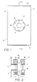
- a cryogenically cooled radiation detection apparatus in accordance with the present invention is shown generally at 10 in Fig. 1.
- the detection apparatus 10 has an outer vessel 11 with a generally cylindrical outer side wall 12 and a flat top wall 13 and bottom wall 14.
- a window structure 15 is formed on the cylindrical side wall 12 and includes a central opening 16 surrounding a window 17 which is transparent to the particular radiation being measured (e.g., infrared electromagnetic radiation).
- a series of bolts 18 are provided for the assembly of the window structure, as described further below.
- a window structure is required since infrared cannot penetrate solid metal.
- the external shape of the detection apparatus 10 is shown as cylindrical, it is apparent that the external shape can be selected as desired provided that sufficient structural integrity is obtained to allow "vacuum" type pressures to be imposed within the walls of the outer vessel 11.
- a cylindrical inner vessel 19 is disposed within the internal cavity of the outer vessel 11 and includes a cylindrical side wall 20, a flat top wall 21 and a flat bottom wall 22 which surround an interior cavity for holding cryogenic coolant.
- a suspending tube 24 having a hollow interior bore 25 extends from attachment to the outer vessel top wall 12 to attachment to the top wall 21 of the inner vessel.
- the bore 25 of the tube 24 provides access from outside the detection apparatus to the interior cavity of the inner vessel 19 to allow coolant to he poured therein.
- the walls of the outer vessel 11, the walls of the inner vessel 19 and the tube 24 are preferably all formed of stainless steel (e.g., 300 series), with the tube 24 being secured by welds 26 and 27 to the outer and inner vessels, respectively.
- Exemplary wall thickness ranges found satisfactory for the outer and inner vessel are, respectively, 0.035 - 0.060 inch (0.089 - 0.152 cm) and 0.020 - 0.040 inch (0.051 - 0.102 cm).
- the welds 26 and 27 additionally serve as seals to prevent the transmission of gases through the junction between the tube and the vessels and establish electrical continuity between the inner and outer vessels, thereby eliminating the need for a ground lead attached to the inner vessel.
- the tube 24 is relatively long, narrow and thin, having a fairly low thermal conduct ion rate, but being in electrical contact with both the inner vessel 19 and the outer vessel 11.
- Satisfactory performance may be obtained with a tube formed of 300 series stainless steel having a wall thickness range of 0.004 - 0.020 inch (0.010 - 0.050 cm), a length range of 0.75 - 1.5 inches or more (1.91 - 3.81 cm), and an outer diameter range of 0.25 - 0.50 inch (0.64 - 1.27 cm).
- the length to area ratio of the tube will be at least 20 cm ⁇ 1.
- the inner vessel 19 is suspended by the tube with its walls spaced away from the inner surfaces of the walls of the outer vessel to define a vacuum chamber space therebetween which can be evacuated to a very low pressure to provide a thermal barrier between the inner and outer vessels.
- the inner and outer surfaces of the outer vessel 11 and the outer surfaces of the inner vessel 19 are highly polished, preferably such that the total emissivity of the surfaces is 0.1 or less.
- the surfaces of the stainless steel vessels will readily accept polishing to achieve a low emissivity.
- the inner surface of the outer vessel 11 and the outer surface of the inner vessel 19 will retain their polished finish indefinitely since the vacuum space which they surround has a relatively low oxygen content, thereby ensuring that oxidation of the inner surfaces proceeds very slowly.
- charcoal getter pellets 30 are preferably affixed to the bottom surface 22 of the inner vessel, such as by adherence using a low temperature epoxy 31. It is preferred that the getters 30 be affixed to the bottom surface of the inner vessel rather than the top surface--the conventional practice--since the bottom surface placement has been found to be more effective in maintaining the low gas pressure within the vacuum chamber.
- a mounting member 33 formed of a good thermal conductor such as copper, is affixed at a foot portion 34 to the outer bottom surface of the inner vessel 19 and extends outwardly into the space between the walls of the inner and outer vessels and upwardly to a position at which the detector device 36 may be mounted.
- the device 36 is attached in good thermal contact with the mounting member 33 so that heat will be conducted away from the detector device 36 through the member 33 to the bottom surface of the inner vessel 19.
- the bottom foot 34 may be brazed to the bottom surface of the stainless steel inner vessel, providing good thermal contact between the two.
- the inner vessel will be periodically filled through the tube 24 with a cryogenic coolant, such as liquid nitrogen, but as the liquid nitrogen warms and boils off (with the gaseous nitrogen being discharged through the bore of the tube 25 to ambient atmosphere), the level of the liquid nitrogen in the inner vessel will drop.
- a cryogenic coolant such as liquid nitrogen
- the coolant level may well drop below the vertical position of the detector device 36. If the detector device 36 were directly adhered to the outer surface of the inner vessel 19, as is conventional, and the coolant level dropped below the position of the detector device, heat would have to be transferred from the detector device through the wall 20 of the inner vessel to the liquid nitrogen within the vessel.
- the stainless steel of which the inner vessel is preferably formed is not an ideal heat conductor, particularly at the relatively thin wall thicknesses which are preferably used in accordance with the present invention, thus presenting the possibility of a substantial temperature differential between the detector 36 and the cryogenic coolant.
- the bottom wall 22 of the inner vessel will be substantially at the temperature of the cryogenic coolant, and the mounting member 33, which has a high heat conductivity, will conduct away heat from the detector device 36 to the bottom wall 22 to maintain the detector device substantially at the coolant temperature no matter what the level of the coolant,
- the detector device 36 is responsive to radiation received through an opening defined by a tubular ring member 40 which is affixed to and extends outwardly from the cylindrical side wall 12 of the outer vessel.
- the ring 40 may be formed integrally with the side wall 12 or may be welded thereto, but in either case is preferably also formed of stainless steel.
- various semiconductor devices may be used for the detector 36, with mercury cadmium telluride (MCT) devices being preferred.
- MCT mercury cadmium telluride
- the signal from the device 36 may be transmitted out from the detector 10 in any appropriate fashion, for example by wires 41 which extend to terminals 42 mounted on the outside of the outer vessel which may be electrically connected to appropriate signal processing equipment.
- the window structure 15 is preferably formed as a standard stainless steel vacuum port of the type known as a "conflat" port.
- the structure 15 includes a first stainless steel fitting 45 having a central internal bore which fits partially over the outer surface of the tubular ring 40 and is welded thereto.
- a second stainless steel fitting 46 has a circular bore with a ledge onto which is mounted the window 17 (for example, formed of zinc selenide for transmission of infrared) which may be cemented in place using a room temperature epoxy with a relatively low outgassing rate.
- a circular copper gasket 47 is mounted between the fittings 45 and 46 to seal the interior of the outer vessel 11 from external atmosphere.
- the fittings 45 and 46 are preferably both formed of stainless steel, compatible in metallury and thermal expansion rate to the metal of the ring 40. As best illustrated in Fig. 2, the fittings 45 and 46 preferably have sharp edged, raised circular ridges 48 and 49, respectively, formed on their facing surfaces which are adapted to engage with the relatively softer copper gasket 47. As the bolts 18 are tightened to draw the two fittings 45 and 46 together, the raised ridges 48 and 49 penetrate into the copper gasket 47 to form a very tight seal which is less subject to leakage than the elastomer O-ring seal customarily used in conventional detectors.
- the above-described structure for the radiation detection apparatus 10 allows simpler initial manufacture than conventional structures.
- the present apparatus is also found to maintain the detector device at a more stable temperature over time. A more permanent vacuum is maintained within the vacuum chamber between the outer vessel 11 and inner vessel 19 because there is less gas permeation through the joints and little or no epoxy resin inside the vacuum chamber. Consequently too, the vacuum chamber may be drawn to a low pressure faster.
- the apparatus 10 avoids a problem which is found commonly in standard Dewar-type radiation detectors: the formation of ice crystals on the inner surfaces of the vacuum chamber.
Landscapes
- Engineering & Computer Science (AREA)
- Physics & Mathematics (AREA)
- General Engineering & Computer Science (AREA)
- Combustion & Propulsion (AREA)
- Mechanical Engineering (AREA)
- Thermal Sciences (AREA)
- Chemical & Material Sciences (AREA)
- General Physics & Mathematics (AREA)
- Spectroscopy & Molecular Physics (AREA)
- Radiation Pyrometers (AREA)
- Details Of Measuring And Other Instruments (AREA)
- Photometry And Measurement Of Optical Pulse Characteristics (AREA)
- Measurement Of Radiation (AREA)
Claims (8)
- Strahlungsnachweiseinrichtung, die auf Tiefsttemperaturen kühlbar ist, mit: einem äußeren Behälter (11) mit Wänden (122, 13, 14), die darin einen inneren Hohlraum definieren, einem inneren Behälter (19), der im inneren Hohlraum des äußeren Behälters angeordnet ist und seinerseits Wände (20, 21, 22) besitzt, die einen inneren Hohlraum definieren, der das Tiefsttemperatur-Kühlmittel enthält; einer Einrichtung (24), die den inneren Behälter (19) im inneren Hohlraum des äußeren Behälters (11) trägt, wobei die Wände des inneren Behälters von den Oberflächen des äußeren Behälters beabstandet sind, und die zwischen der umgebenden Atmosphäre und dem inneren Hohlraum des inneren Behälters eine Verbindung schafft; einer Fensterstruktur (15), die die nachzuweisende Strahlung durch ein Fenster (17) an eine Öffnung (40) in der Außenwand (12) des äußeren Behälters (11) durchläßt und dabei die zwischen dem inneren Behälter und dem äußeren Behälter definierte Vakuumkammer gegenüber der umgebenden Atmosphäre abdichtet; und einem Strahlungsdetektor (36) für die Erfassung der einfallenden Strahlung und die Erzeugung eines diese Strahlung angebenden Ausgangssignals, der in einer Wärmeaustauschbeziehung an der Bodenwand (22) des inneren Behälters (19) in der Umgebung der Fensterstruktur (15) angebracht ist, um die durch die Fensterstruktur (15) durchgelassene Strahlung zu empfangen, wobei der Detektor (36) durch den Wärmeaustausch auf einer Temperatur gehalten wird, die im wesentlichen die Temperatur der Bodenwand (22) des inneren Behälters (19) ist, dar seinerseits im wesentlichen auf der Temperatur des Tiefsttemperatur-Kühlmittels im inneren Hohlraum des inneren Behälters gehalten wird,
dadurch gekennzeichnet, daß sich die Öffnung (40) im äußeren Behälter (11), an der die Fensterstruktur (15) angebracht ist, in einer Seitenwand (12) des Behälters befindet und daß die Wärmeaustauschbeziehung mit der Bodenwand des inneren Behälters durch ein Anbringungselement (33) bewerkstelligt wird, das aus einem hochwärmeleitenden Metall gebildet ist, das an der Bodenwand (22) des inneren Behälters (19) in einen Wärmeaustauschkontakt mit diesem angebracht ist und sich nach außen und dann vom Anbringungspunkt in der Vakuumkammer in einem Abstand zu den Wänden des inneren Behälters (11) und des äußeren Behälters (19) nach oben an eine Position bei der Öffnung (40) im äußeren Behälter erstreckt, an welcher die Fensterstruktur (15) angebracht ist, wobei der Strahlungsdetektor (36) in einen Wärmeaustauschkontakt am Anbringungselement (33) angebracht ist. - Einrichtung gemäß Anspruch 1, bei der der innere und der äußere Behälter (15, 19) aus rostfreiem Stahl hergestellt sind und die Einrichtung zum Tragen des inneren Behälters ein Hohlrohr aus rostfreiem Stahl (24) enthält, das an einer Wand (13) des äußeren Behälters (11) befestigt ist und sich zu einer Wand (21) des inneren Behälters (19) erstreckt und an dieser befestigt ist, wobei die Innenbohrung (25) des Rohrs eine Verbindung zwischen der umgebenden Atmosphäre und dem inneren Hohlraum des inneren Behälters schafft und wobei das Hohlrohr (24) den inneren Behälter (19) im äußeren Behälter (11) trägt, wobei die Wände (20, 21, 22) des inneren Behälters (19) von den Innenflächen des äußeren Behälters beabstandet sind, um zwischen dem inneren und dem äußeren Behälter eine Vakuumkammer zu definieren.
- Einrichtung gemäß Anspruch 2, bei der der innere und der äußere Behälter (19, 11) jeweils zylindrische Form haben, wobei jeder eine Zylindrische Außenwand (20, 12) und eine flache obere Wand und eine flache untere Wand (21, 13, 22, 14) besitzt, und bei der sich das Aufhängungsrohr (24) vom Befestigungspunkt (26) an der oberen Wand (13) des äußeren Behälters (11) zum Befestigungspunkt (27) an der oberen Wand (21) des inneren Behälters (19) erstreckt.
- Einrichtung gemäß einem vorangehenden Anspruch, bei der die Fensterstruktur (15) versehen ist mit einem ersten und mit einem zweiten Anschlußstück (45, 46) aus rostfreiem Stahl, wobei das erste Anschlußstück (45) an einem vom äußeren Behälter (11) sich erstreckenden rohrförmigen Ring (40) fest angebracht ist und die Anschlußstücke spitz zulaufende Rippen (48, 49) besitzen, die eine mittige Bohrung eines jeden Anschlußstücks umgeben, einer Kupferdichtung (47), die so beschaffen ist, daß sie zwischen den spitz zulaufenden Rippen (48, 49) am ersten und am zweiten Anschlußstück (45, 46) in Eingriff gelangen kann, wenn die Anschlußstücke zusammengezogen werden, Schraubbolzen (18), die mit den Anschlußstücken (45, 46) in Eingriff sind, um die Anschlußstücke eng zusammenzuhalten, und einem Fenster (17), das für die nachzuweisende Strahlung durchlässig ist und am zweiten Anschlußstück (46) angebracht ist, um dessen Bohrung zu verschließen, um die Vakuumkammer zwischen dem inneren und dem äußeren Behälter gegenüber der umgebenden Atmosphäre abzudichten.
- Einrichtung gemäß einem vorangehenden Anspruch, bei der der Stahlungsdetektor einen auf Infrarotstrahlung ansprechenden Halbleiter (36) enthält.
- Einrichtung gemäß einem vorangehenden Anspruch, bei der die äußere Oberfläche des inneren Behälters (19) und die innere und die äußere Oberfläche des äußeren Behälters (11) hochgradig poliert sind, um die auf sie einfallende Infrarotstrhalung im wesentlichen zu reflektieren.
- Einrichtung gemäß einem vorangehenden Anspruch, die Getter (30) für das an der äußeren Oberfläche der Bodenwand (22) des inneren Behälters (19) anhaftende Restgas enthält.
- Einrichtung gemäß einem vorangehenden Anspruch, bei der das Anbringungselement (23) aus Kupfer gebildet und am Boden (22) des inneren Behälters (19) durch Löten angebracht ist.
Priority Applications (1)
| Application Number | Priority Date | Filing Date | Title |
|---|---|---|---|
| AT87901227T ATE95920T1 (de) | 1986-01-22 | 1987-01-20 | Strahlungsnachweisvorrichtung mit gefrierkuehlung. |
Applications Claiming Priority (2)
| Application Number | Priority Date | Filing Date | Title |
|---|---|---|---|
| US06/821,277 US4740702A (en) | 1986-01-22 | 1986-01-22 | Cryogenically cooled radiation detection apparatus |
| US821277 | 2007-06-22 |
Publications (3)
| Publication Number | Publication Date |
|---|---|
| EP0253883A1 EP0253883A1 (de) | 1988-01-27 |
| EP0253883A4 EP0253883A4 (de) | 1989-11-07 |
| EP0253883B1 true EP0253883B1 (de) | 1993-10-13 |
Family
ID=25232990
Family Applications (1)
| Application Number | Title | Priority Date | Filing Date |
|---|---|---|---|
| EP87901227A Expired - Lifetime EP0253883B1 (de) | 1986-01-22 | 1987-01-20 | Strahlungsnachweisvorrichtung mit gefrierkühlung |
Country Status (5)
| Country | Link |
|---|---|
| US (1) | US4740702A (de) |
| EP (1) | EP0253883B1 (de) |
| JP (1) | JPH0695045B2 (de) |
| DE (1) | DE3787766T2 (de) |
| WO (1) | WO1987004519A1 (de) |
Families Citing this family (8)
| Publication number | Priority date | Publication date | Assignee | Title |
|---|---|---|---|---|
| US4944155A (en) * | 1989-06-14 | 1990-07-31 | Kadel Engineering Corporation | Vacuum separator for dewar flask cold exchange systems |
| US5054936A (en) * | 1989-11-16 | 1991-10-08 | Jacob Fraden | Sensor for active thermal detection |
| US5086619A (en) * | 1990-06-15 | 1992-02-11 | Nicolet Instrument Corporation | Filler apparatus for providing cryogenic liquid coolant to dewars such as those used in radiation detectors |
| US5772773A (en) * | 1996-05-20 | 1998-06-30 | Applied Materials, Inc. | Co-axial motorized wafer lift |
| US6979119B2 (en) * | 2003-04-30 | 2005-12-27 | Raytheon Company | Sensor system and method for sensing in an elevated-temperature environment, with protection against external heating |
| US9194750B2 (en) * | 2009-10-07 | 2015-11-24 | Semi Conductor Devices—Elbit Systems—Rafael Partnership | Infra-red imager |
| EP2916112B1 (de) * | 2014-03-05 | 2016-02-17 | VEGA Grieshaber KG | Radiometrische Messanordnung |
| CN115704714A (zh) * | 2021-08-16 | 2023-02-17 | 北京振兴计量测试研究所 | 基于shutter调制原理的超低温真空红外辐射计 |
Citations (1)
| Publication number | Priority date | Publication date | Assignee | Title |
|---|---|---|---|---|
| JPS6148A (ja) * | 1984-05-29 | 1986-01-06 | チバ‐ガイギー アクチエンゲゼルシヤフト | α‐クロロアセト酢酸モノメチルアミドの製造方法 |
Family Cites Families (31)
| Publication number | Priority date | Publication date | Assignee | Title |
|---|---|---|---|---|
| US3180989A (en) * | 1962-01-11 | 1965-04-27 | Lockheed Aircraft Corp | Cryogenic flask for a cooled infrared detector including an evacuated space for the infrared detector |
| DE1931581A1 (de) * | 1969-06-21 | 1970-12-23 | Philips Nv | Kryostatdetektor |
| US3596096A (en) * | 1970-03-13 | 1971-07-27 | Us Air Force | Dual temperature apparatus for testing infrared radiation detectors |
| US3889119A (en) * | 1973-06-25 | 1975-06-10 | Texas Instruments Inc | Cryogenic cooler off-axis drive mechanism for an infrared receiver |
| US3999403A (en) * | 1974-12-06 | 1976-12-28 | Texas Instruments Incorporated | Thermal interface for cryogen coolers |
| BE847581A (fr) * | 1975-11-03 | 1977-02-14 | Citerne isolee pour liquides cryogeniques, | |
| US4206354A (en) * | 1976-07-09 | 1980-06-03 | Honeywell Inc. | Axial matrix Dewar |
| US4194119A (en) * | 1977-11-30 | 1980-03-18 | Ford Motor Company | Self-adjusting cryogenic thermal interface assembly |
| US4172225A (en) * | 1978-01-09 | 1979-10-23 | Kevex Corporation | Alpha particle x-ray energy analysis system |
| US4212169A (en) * | 1978-02-21 | 1980-07-15 | Varian Associates, Inc. | Cryostat for superconducting NMR spectrometer |
| GB2027181B (en) * | 1978-06-21 | 1982-09-02 | Philips Electronic Associated | Detectors and envelope arrangements for detectors |
| US4184609A (en) * | 1978-08-22 | 1980-01-22 | The United States Of America As Represented By The Administrator Of The National Aeronautics And Space Administration | Cryogenic container compound suspension strap |
| JPS5561048A (en) * | 1978-10-31 | 1980-05-08 | Fujitsu Ltd | Cooled type photoelectric converter |
| DE2905593A1 (de) * | 1979-02-14 | 1980-08-21 | Krupp Gmbh | Druckbehaelter fuer heisse medien |
| DE2942164C3 (de) * | 1979-10-18 | 1982-03-25 | Kernforschungsanlage Jülich GmbH, 5170 Jülich | Wandabstützung von Doppelwandbehältern, insbesondere von Dewar-Gefäßen und damit versehene Behälter |
| US4412427A (en) * | 1980-04-03 | 1983-11-01 | The United States Of America As Represented By The Secretary Of The Army | Noncontact thermal interface |
| US4324104A (en) * | 1980-04-03 | 1982-04-13 | The United States Of America As Represented By The Secretary Of The Army | Noncontact thermal interface |
| IT1209844B (it) * | 1981-02-09 | 1989-08-30 | Selenia Ind Elettroniche | Dispositivo per rivelazione dell'infrarosso a molti elementi ad elevata densita' di passanti a bassa per dita termica |
| US4479367A (en) * | 1981-12-28 | 1984-10-30 | Santa Barbara Research Center | Thermal filter |
| GB2115602B (en) * | 1982-02-24 | 1986-01-02 | Philips Electronic Associated | Getters in infra-red radiation detectors |
| US4454481A (en) * | 1982-03-04 | 1984-06-12 | Rockwell International Corporation | Shielded amplifier |
| DE3222064C2 (de) * | 1982-06-11 | 1987-01-15 | Georg Noell GmbH, 2000 Hamburg | Behälter zur Einlagerung von tiefgekühlten Flüssigkeiten |
| US4496073A (en) * | 1983-02-24 | 1985-01-29 | The Johns Hopkins University | Cryogenic tank support system |
| US4459823A (en) * | 1983-03-30 | 1984-07-17 | Sperry Corporation | Rotating liquid nitrogen cooled substrate holder |
| US4450693A (en) * | 1983-05-24 | 1984-05-29 | Honeywell Inc. | Cryogenic cooler thermal coupler |
| US4488414A (en) * | 1983-10-03 | 1984-12-18 | Honeywell Inc. | Disc detector assembly |
| NL8303603A (nl) * | 1983-10-19 | 1985-05-17 | Philips Nv | Infrarood ontvanger met gekoelde stralingsdetector. |
| GB8328236D0 (en) * | 1983-10-21 | 1983-11-23 | British Petroleum Co Plc | Cryogenic cell |
| JPS60146121A (ja) * | 1984-01-11 | 1985-08-01 | Mitsubishi Electric Corp | 赤外線検知器 |
| US4487332A (en) * | 1984-02-02 | 1984-12-11 | Nicolet Instrument Corporation | Cryostat vessel wall spacing system |
| US4537328A (en) * | 1984-05-14 | 1985-08-27 | Keesee Tank And Pump Co., Inc. | Storage tank |
-
1986
- 1986-01-22 US US06/821,277 patent/US4740702A/en not_active Expired - Lifetime
-
1987
- 1987-01-20 JP JP62501216A patent/JPH0695045B2/ja not_active Expired - Fee Related
- 1987-01-20 DE DE87901227T patent/DE3787766T2/de not_active Expired - Fee Related
- 1987-01-20 EP EP87901227A patent/EP0253883B1/de not_active Expired - Lifetime
- 1987-01-20 WO PCT/US1987/000163 patent/WO1987004519A1/en not_active Ceased
Patent Citations (1)
| Publication number | Priority date | Publication date | Assignee | Title |
|---|---|---|---|---|
| JPS6148A (ja) * | 1984-05-29 | 1986-01-06 | チバ‐ガイギー アクチエンゲゼルシヤフト | α‐クロロアセト酢酸モノメチルアミドの製造方法 |
Also Published As
| Publication number | Publication date |
|---|---|
| US4740702A (en) | 1988-04-26 |
| JPS63502614A (ja) | 1988-09-29 |
| DE3787766D1 (de) | 1993-11-18 |
| EP0253883A4 (de) | 1989-11-07 |
| EP0253883A1 (de) | 1988-01-27 |
| DE3787766T2 (de) | 1994-02-10 |
| JPH0695045B2 (ja) | 1994-11-24 |
| WO1987004519A1 (en) | 1987-07-30 |
Similar Documents
| Publication | Publication Date | Title |
|---|---|---|
| US3258602A (en) | Photodetecting apparatus having cryo- genic cooling and flushing means | |
| US5177364A (en) | Infrared detector construction including a getter and method for manufacturing same | |
| US6122919A (en) | Sensor/cooling system with cold finger having recessed end | |
| US4501131A (en) | Cryogenic cooler for photoconductive cells | |
| US4740702A (en) | Cryogenically cooled radiation detection apparatus | |
| US4621279A (en) | Non-evacuated, rapidly coolable housing for an opto-electronic semiconductor component | |
| US8637824B2 (en) | Cold shield for a cold stage | |
| US4510758A (en) | Convertible cryostat | |
| US11150140B2 (en) | Instrumented substrate apparatus for acquiring measurement parameters in high temperature process applications | |
| CA1268865A (en) | Modular photon detector cryostat assembly and system | |
| EP0136687A2 (de) | Infrarotdetektor | |
| US3836779A (en) | Cooling apparatus for infrared detectors | |
| US4944155A (en) | Vacuum separator for dewar flask cold exchange systems | |
| US3180989A (en) | Cryogenic flask for a cooled infrared detector including an evacuated space for the infrared detector | |
| EP0265486B1 (de) | Modularer photonendetektor-cryostat, zusammenbau und system | |
| US3259865A (en) | Dewar for cryogenic cooling of solid state device | |
| US3697825A (en) | Radiation detector | |
| RU10877U1 (ru) | Приемник ик излучения | |
| Palumbo et al. | Balloon-borne 3He cryostat for millimetre bolometric photometry | |
| Ellison | Hybrid liquid helium cryostat for radio astronomy use | |
| US3185842A (en) | Method of stabilization of dewar package thin film detectors | |
| US3052861A (en) | Bolometer | |
| SU1709157A1 (ru) | Криостат | |
| JPH03128469A (ja) | 超電導電磁波検出器 | |
| Lagus et al. | Solidified gas samples for shock wave experimentation |
Legal Events
| Date | Code | Title | Description |
|---|---|---|---|
| PUAI | Public reference made under article 153(3) epc to a published international application that has entered the european phase |
Free format text: ORIGINAL CODE: 0009012 |
|
| AK | Designated contracting states |
Kind code of ref document: A1 Designated state(s): AT BE CH DE FR GB IT LI LU NL SE |
|
| 17P | Request for examination filed |
Effective date: 19880106 |
|
| RHK1 | Main classification (correction) |
Ipc: G01J 5/06 |
|
| A4 | Supplementary search report drawn up and despatched |
Effective date: 19891107 |
|
| 17Q | First examination report despatched |
Effective date: 19920312 |
|
| GRAA | (expected) grant |
Free format text: ORIGINAL CODE: 0009210 |
|
| AK | Designated contracting states |
Kind code of ref document: B1 Designated state(s): AT BE CH DE FR GB IT LI LU NL SE |
|
| PG25 | Lapsed in a contracting state [announced via postgrant information from national office to epo] |
Ref country code: IT Free format text: LAPSE BECAUSE OF FAILURE TO SUBMIT A TRANSLATION OF THE DESCRIPTION OR TO PAY THE FEE WITHIN THE PRE;WARNING: LAPSES OF ITALIAN PATENTS WITH EFFECTIVE DATE BEFORE 2007 MAY HAVE OCCURRED AT ANY TIME BEFORE 2007. THE CORRECT EFFECTIVE DATE MAY BE DIFFERENT FROM THE ONE RECORDED.SCRIBED TIME-LIMIT Effective date: 19931013 Ref country code: CH Effective date: 19931013 Ref country code: BE Effective date: 19931013 Ref country code: SE Effective date: 19931013 Ref country code: AT Effective date: 19931013 Ref country code: NL Effective date: 19931013 Ref country code: LI Effective date: 19931013 |
|
| REF | Corresponds to: |
Ref document number: 95920 Country of ref document: AT Date of ref document: 19931015 Kind code of ref document: T |
|
| REF | Corresponds to: |
Ref document number: 3787766 Country of ref document: DE Date of ref document: 19931118 |
|
| ET | Fr: translation filed | ||
| PGFP | Annual fee paid to national office [announced via postgrant information from national office to epo] |
Ref country code: SE Payment date: 19940125 Year of fee payment: 8 |
|
| PGFP | Annual fee paid to national office [announced via postgrant information from national office to epo] |
Ref country code: LU Payment date: 19940131 Year of fee payment: 8 Ref country code: NL Payment date: 19940131 Year of fee payment: 8 |
|
| REG | Reference to a national code |
Ref country code: CH Ref legal event code: PL |
|
| EPTA | Lu: last paid annual fee | ||
| NLV1 | Nl: lapsed or annulled due to failure to fulfill the requirements of art. 29p and 29m of the patents act | ||
| PLBE | No opposition filed within time limit |
Free format text: ORIGINAL CODE: 0009261 |
|
| STAA | Information on the status of an ep patent application or granted ep patent |
Free format text: STATUS: NO OPPOSITION FILED WITHIN TIME LIMIT |
|
| 26N | No opposition filed | ||
| PG25 | Lapsed in a contracting state [announced via postgrant information from national office to epo] |
Ref country code: LU Free format text: LAPSE BECAUSE OF NON-PAYMENT OF DUE FEES Effective date: 19950120 |
|
| PGFP | Annual fee paid to national office [announced via postgrant information from national office to epo] |
Ref country code: GB Payment date: 20001211 Year of fee payment: 15 |
|
| PGFP | Annual fee paid to national office [announced via postgrant information from national office to epo] |
Ref country code: FR Payment date: 20010103 Year of fee payment: 15 |
|
| PGFP | Annual fee paid to national office [announced via postgrant information from national office to epo] |
Ref country code: DE Payment date: 20010126 Year of fee payment: 15 |
|
| REG | Reference to a national code |
Ref country code: GB Ref legal event code: IF02 |
|
| PG25 | Lapsed in a contracting state [announced via postgrant information from national office to epo] |
Ref country code: GB Free format text: LAPSE BECAUSE OF NON-PAYMENT OF DUE FEES Effective date: 20020120 |
|
| PG25 | Lapsed in a contracting state [announced via postgrant information from national office to epo] |
Ref country code: DE Free format text: LAPSE BECAUSE OF NON-PAYMENT OF DUE FEES Effective date: 20020801 |
|
| GBPC | Gb: european patent ceased through non-payment of renewal fee |
Effective date: 20020120 |
|
| PG25 | Lapsed in a contracting state [announced via postgrant information from national office to epo] |
Ref country code: FR Free format text: LAPSE BECAUSE OF NON-PAYMENT OF DUE FEES Effective date: 20020930 |
|
| REG | Reference to a national code |
Ref country code: FR Ref legal event code: ST |