EP0254505A2 - Distributeur de liquide du type à gâchette - Google Patents
Distributeur de liquide du type à gâchette Download PDFInfo
- Publication number
- EP0254505A2 EP0254505A2 EP87306367A EP87306367A EP0254505A2 EP 0254505 A2 EP0254505 A2 EP 0254505A2 EP 87306367 A EP87306367 A EP 87306367A EP 87306367 A EP87306367 A EP 87306367A EP 0254505 A2 EP0254505 A2 EP 0254505A2
- Authority
- EP
- European Patent Office
- Prior art keywords
- cylindrical member
- trigger
- intake
- piston unit
- engaging
- Prior art date
- Legal status (The legal status is an assumption and is not a legal conclusion. Google has not performed a legal analysis and makes no representation as to the accuracy of the status listed.)
- Granted
Links
Images



Classifications
-
- B—PERFORMING OPERATIONS; TRANSPORTING
- B05—SPRAYING OR ATOMISING IN GENERAL; APPLYING FLUENT MATERIALS TO SURFACES, IN GENERAL
- B05B—SPRAYING APPARATUS; ATOMISING APPARATUS; NOZZLES
- B05B11/00—Single-unit hand-held apparatus in which flow of contents is produced by the muscular force of the operator at the moment of use
- B05B11/01—Single-unit hand-held apparatus in which flow of contents is produced by the muscular force of the operator at the moment of use characterised by the means producing the flow
- B05B11/10—Pump arrangements for transferring the contents from the container to a pump chamber by a sucking effect and forcing the contents out through the dispensing nozzle
- B05B11/1001—Piston pumps
- B05B11/1009—Piston pumps actuated by a lever
- B05B11/1011—Piston pumps actuated by a lever without substantial movement of the nozzle in the direction of the pressure stroke
Definitions
- the present invention relates to a trigger type liquid dispenser mounted at a liquid container to dispense or atomize liquid in the container.
- a conventional trigger type liquid dispenser is disclosed, for example, in Japanese Patent Publication No. 41726/1979 and Japanese Utility Model Publication No 920/1986.
- Each of both has a dispenser body detachably engaged with the neck of a liquid container, a pump manually driven by a trigger to intake the liquid in the container in the body, and a nozzle unit for exhausting the pressurized liquid to exhaust the liquid of the container by manually operating the trigger.
- the liquid dispenser disclosed in Japanese Patent Publication No. 41726/1979 further employs a pump chamber also used as a spring chamber, a spring mounted in the pump chamber so that the spring is always dipped directly in the exhausting liquid.
- the spring is readily rusted or dissolved in the liquid, and this type has such a drawback that the dispenser is restricted in the utility.
- the liquid dispenser disclosed in Japanese Utility Model Publication No. 920/1986 employs double walled inner and outer cylindrical members, and uses the inner cylindrical member as a pump chamber and a spring mounted in the pump chamber so that the spring is always dipped in the discharging liquid.
- This dispenser also has similar drawback to the above dispenser.
- the trigger is readily removed from the body before the step of assembling the nozzle in case of temporarily assembling the trigger at the body when associating the dispenser to hardly improve the assembling productivity.
- the above-said Japanese Utility Model Publication No. 920/1986 discloses an atomizing head (exhaust element) of a trigger unit to be covered on ten end of an injecting cylinder (exhausting cylinder).
- the conventional trigger type liquid dispenser is constructed as disclosed in Japanese Utility Model Publication No. 920/1981 that the inner cylindrical member is merely inserted into the outer cylindrical member.
- one primary object of the present invention to provide a trigger type liquid dispenser which can eliminate the above-mentioned troubles, drawbacks and disadvantages of the conventional liquid dispenser and can protect a spring, complete a pumping action and smoothly execute the intaking operation of a liquid container.
- Another object of the present invention is to provide a trigger type liquid dispenser which can eliminate the removal of a trigger from a body irrespective of the rotating position of the trigger.
- Yet another object of the present invention is to provide a trigger type liquid dispenser which can readily and rapidly assemble an exhaust cylindrical member with an engaging cylindrical portion in case of assembling an exhaust element with a body.
- Still another object of the invention is to provide a trigger type liquid dispenser which can much reduce the leakage of the liquid from the liquid dispenser to increase the exhausting efficiency.
- a trigger type liquid dispenser having a nozzle unit including a nozzle at its front end, a pump operated by a trigger and a container mount, comprising said pump operated by the trigger having an annular cylinder including concentric outer and inner cylindrical members of double wall shape projected forwardly of a body, and a piston unit telescoped in the annular cylinder and having an annular piston sliding on the inner surface of the outer cylindrical member and the outer surface of the inner cylindrical member, said piston unit having skirts annularly flared at the axial edges of the sliding surfaces as the sliding surfaces of the piston unit with the surface of the inner and outer cylindrical members, a spring contained in a spring chamber formed of a bore made of the inner cylindrical member of the annular cylinder and the piston unit telescoped in the inner cylindrical member at the axial center side for urging the piston unit outward of the axial center, said spring chamber capable of communicating with the atmosphere, and an intake valve for communicating the atmospheric air with the neck of the container whenever the piston unit
- the spring is not always dipped in the exhaust liquid. Since the spring is completely contained in the spring chamber, the spring itself is not damaged nor does not hurt the operator, but the pumping action of the pump can be competely executed to smoothly execute the intaking operation of the liquid container, and no liquid is leaked from the dispenser.
- a trigger type liquid dispenser further comprising, in the first aspect, a pair of opposed right and left lip-shaped engaging grooves formed in section on the inner surface of the sidewall 110 of a body, a pair of lugs each having a base and an end of larger diameter than the base, projected perpendicularly to the trigger oppositely from both lateral sides thereof at the fork portions of the trigger in such a manner that the ends of the lugs are inserted into the spaces of the grooves, respectively, the bases of the lugs disposed respectively in the spaces formed at the fork portions to be narrower than the spaces of the grooves of the body and the ends of the lugs rotatably restricted in the grooves of the body.
- the trigger can be reliably mounted on the body irrespective of the mounting of the nozzle.
- the upper end of the sidewall of the trigger can be always restricted at the ends of the lug with the engaging grooves irrespective of the rotating position of the trigger to eliminate the removal of the trigger from the body.
- a trigger type liquid dispenser having an exhaust cylindrical member projected in a bore surrounded by an upper wall, a left sidewall and a right sidewall of a body and a piston unit telescoped by a trigger in the bore comprises, in the first aspect, a guide rail projected to arrive at the front end of the body in parallel with the exhaust cylindrical member in the upper wall, and guide pieces projected on the outer surface of the engaging cylindrical portion in parallel with the axial direction of the engaging portion to interpose the guide rail therebetween.
- the exhaust element can be accurately and smoothly assembled with the body.
- the engaging position of the exhaust cylindrical member with the engaging cylindrical portion can be readily defined in case of assembling the exhaust element with the body to rapidly execute the assembling steps thereafter.
- a trigger type liquid dispenser having an intake outer cylindrical member opened at its lower end with a body, and a hollow intake inner cylindrical member having a ball valve of an intake valve body and an exhaust valve body engaged within the intake outer cylindrical member to be able to dispense liquid by a trigger
- a trigger comprising an intake inner cylindrical member mounting structure having a mounting short cylindrical member flared outwardly at the lower end of the body, integrally formed with the intake outer cylindrical member, an extended cylindrical portion projected from the lower end of the intake outer cylindrical member into the mounting short cylindrical member, the engaging cylindrical portion of the intake inner cylindrical member being inserted into the intake outer cylindrical member, an engaging annular cylindrical groove recessed on the periphery of the lower end of the engaging cylindrical portion so that the extended cylindrical portion is inserted into the engaging annular cylindrical groove and the lower end of the intake inner cylindrical member is flared to be inserted into the mounting short cylindrical member.
- the liquid to be able to be leaked under pressure to a gap between the intake outer cylindrical member and the engaging cylindrical portion of the intake inner cylindrical member is much reduced due to the engaging surface between the extended cylindrical portion and the engaging annular cylindrical groove in addition to the engaging surface between the intake outer cylindrical member and the engaging cylindrical portion of the intake inner cylindrical member to thereby increasing the exhausting efficiency of the liquid.
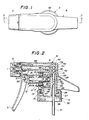
- a trigger type liquid dispenser has a nozzle unit 2 having a nozzle 1 at its front end, a pump 4 operated by a trigger 3 and a container mount 5.
- the pump 4 operated by the trigger 3 has an annular cylinder 9 having concentric outer and inner cylindrical members 7 and 8 of double wall shape projected forwardly of a body 6, and a piston unit 12 telescoped in the annular cylinder 9 and having an annular piston 49 sliding on the inner surface 10 of the outer cylindrical member 7 and the outer surface 11 of the inner cylindrical member 8.
- the piston unit 12 has an inner skirt 14 annularly flared inwardly at the axially inner edge of the inner sliding surface 13 as the sliding surface of the piston unit 12 with the outer surface 11 of the inner cylindrical member 8, inside outer skirt 16 and outside outer skirt 17 flared outwardly at the axially inner and outer edges of the outer sliding surface 15 as the sliding surface of the piston unit 12 with the inner surface 10 of the outer cylindrical member 7 to form the annular piston 49.
- a spring 20 is contained in a spring chamber 19 formed of a bore 18 made of the inner cylindrical member 8 of the annular cylinder 9 and the piston unit 12 telescoped in the inner cylindrical member 8 at the axial center side for urging the piston unit 12 outward of the axial center.
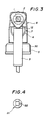
- the spring chamber 19 always communicates with the atmosphere through an air opening 22 perforated at the head 21 of the piston unit 12 as shown in Figs. 2 and 4.
- An intake valve 23 is formed of the outside outer skirt 17 and the inside outer skirt 16 formed at outer cylindrical member 7 and the outer sliding surface 16 of the piston unit 12 to intake the atmospheric air supplied to the container whenever the piston unit 12 is operated by the trigger to be described later.
- An intake outer cylindrical member 24 is elevationally formed adjacent to the rear end of the annular cylinder 9 of the body 6, and an intake inner cylindrical member 25 is engaged within the intake outer cylindrical member 24.
- An engaging portion 26 is flared at the lower end of the intake inner cylindrical member 25, and a flange 27 is projected to contact with the neck of the container.
- An engaging outer ring 28 fixedly secured to the engaging portion 26 of the intake inner cylindrical member 25 and an engaging groove 29 formed at the lower edge of the body 6 to be inserted with the engaging portion 25 perform a function of preventing the intake inner cylindrical member 25 from being removed out of the body 6 by inserting the engaging outer ring 28 into the groove 29 of the body 6.
- a cap 30 is rotatably engaged with the flange 27 so as not to remove from the flange 27 to form the container mount 5.
- a dip tube 31 which can arrive at the bottom of the container is inserted into the lower end of the intake inner cylindrical member 25 in the cap 30, a ball valve seat 33 is formed through a valve opening 32 at the upper end of the tube 31, a cylindrical intervalve chamber 34 is formed above the ball valve seat 33, and a ball valve 35 is contained in the intervalve chamber 34.
- a cylinder chamber 36 formed between the outer cylindrical member 7 and the inner cylindrical member 8 of the pump 4 communicates with the intervalve chamber 34 through a cylinder opening 37 perforated at the bottom of the cylinder chamber 36 and an intake inner cylindrical member opening 38 perforated at the intake inner cylindrical member 25.
- a large-diameter exhaust valve chamber 39 is integrally formed at the upper end of the intervalve chamber 34, and an exhaust valve body 40 is mounted in the valve chamber 39.
- the exhaust valve body 40 is formed at its lower end with a valve flange 42 to be contacted with an exhaust valve seat 41 formed at the lower end of the exhaust valve chamber 39, is formed at its upper end with a connecting end 43 to be connected with the exhaust valve chamber 39, and is formed with a double ring-shaped stretchable elastic portion 44 at the intermediate between the connecting end 43 and the valve flange 42 for ordinarily urging the valve flange 42 in a direction to contact with the exhaust valve seat 41.
- An exhaust passage 45 is formed from the exhaust valve chamber 39 forwardly to communicate with the nozzle 1 of the nozzle unit 2.
- a connecting opening 46 is perforated at the upper end of the engaging portion 26 of the inner cylindrical member 25, a vent hole 47 is perforated at the lowermost side of the outer cylindrical member 7, and the vent hole 47 communicates through a groove 48 with the connecting opening 46.
- vent hole 47 is so perforated, as shown in Fig. 2, at the intermediate that the inside outer skirt 16 and the outside outer skirt 17 are contacted with the inner surface of the outer cylindrical member where the piston unit 12 is disposed to be forwardly projected at the frontmost side, that the piston unit 12 is retreated by the trigger 3 to be disposed forwardly from the position of the outside outer skirt 17.
- the nozzle unit exemplified in the drawings may employ various shapes.
- the nozzle unit illustrated in the drawings is for foaming or spraying.
- the cylinder 9 of the pump 4 is formed in double of inner and outer cylindrical members in such a manner that the spring chamber 19 is formed in the inner cylindrical member 8 and the spring chamber 19 always communicates with the atmosphere, the spring 20 is not dipped in the exhausted liquid at all, the spring 20 is not thus rusted nor dissolved to cause no trouble to occur due to the spring 20. Further, since the cylinder chamber 36 is formed between the inner and the outer cylindrical members and the skirts 14, 16 are formed at the sliding portions of the piston unit 12 and the cylinder chamber 35, a separate seal is not necessary.
- the dispenser can be readily mounted at various liquid containers to be operated simply to be thus adapted for a variety of liquid dispensers.
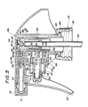
- a trigger type liquid dispenser of this modified example has a nozzle unit 52 having a nozzle 51 at its front end, a pump 54 operated by a trigger 53 and a container mount 55.
- the pump 54 operated by the trigger 53 has an annular cylinder 59 having concentric outer and inner cylindrical members 57 and 58 of double wall shape projected forwardly of a body 56, and a piston unit 62 telescoped in the annular cylinder 59 and having an annular piston 50 sliding on the inner surface 60 of the outer cylindrical member 57 and the outer surface 61 of the inner cylindrical member 58.
- the piston unit 62 has a head 71 contacted with the trigger 53, a piston outer cylindrical member 74 formed at its rear end with the annular piston 50 telescoped in the annular cylinder 59 formed of the outer and inner cylindrical members 57, 58, and a piston inner cylindrical member 75 telescoped in the inner cylindrical member 58 cooperatively provided with the piston outer cylindrical member 74 in a double wall shape.
- the annular piston 50 has an inner skirt 64 annularly flared inwardly at the axially inner edge of the inner sliding surface 63 as the sliding surface of the piston unit 62 to be slidably contacted with the outer surface 61 of the inner cylindrical member 58, an outer skirt 66 annularly flared outwardly at the axially inner edge of the outer sliding surface 55 as the sliding surface of the piston unit 62 to be slidably contacted with the inner surface 60 of the outer cylindrical member 57, and an inner cylindrical skirt 77 annularly flared outwardly at the inner edge of the piston inner cylindrical member 75 to be slidably contacted with the small-diameter inner surface 76 of the inner cylindrical member 58 near the end of the inner cylindrical member 58.
- a spring 70 is contained in a spring chamber 69 formed of a bore 68 made of the inner cylindrical member 58 of the annular cylinder 59 and the piston unit 62 telescoped in the inner cylindrical member 58 for urging the piston unit 62 outward of the axial center.
- the inner surface of the inner cylindrical member 58 is formed as a large-diameter inner surface 78 to the rear end continued to the small-diameter inner surface 61 near the end of the inner cylindrical member 58.
- a vent hole 79 is perforated at the rear end of the spring chamber 69, and an air opening 72 is perforated at the piston outer cylindrical member 74 to communicate with the atmosphere.
- An outer cylindrical member 81 is elevationally formed adjacent to the rear ends of the annular cylinder 59 of the body 56 and the spring chamber 69, and an inner cylindrical member 82 is engaged within the outer cylindrical member 81.
- An engaging portion 83 is flared at the lower end of the inner cylindrical member 82, and a flange 84 is projected to contact with the neck of the container.
- An engaging outer ring 28 fixedly secured to the engaging portion 83 of the intake inner cylindrical member 82.
- a cap 85 is rotatably engaged with the flange 84 so as not to remove from the flange 84 to form the container mount 55.
- a dip tube 86 which can arrive at the bottom of the container is inserted into the inner cylindrical member 82, an intake valve seat 88 is formed through an intake valve opening 87 at the upper end of the tube 86, an intervalve chamber 89 is formed above the intake valve seat 88, and an intake valve 93 integrally formed with an intake valve sheet 92 through an elastic support 91 at an intake valve head 90 is mounted in the intervalve chamber 89.
- the annular cylinder 59 of the pump 59 communicates through a cylinder opening 80 perforated at the bottom of the cylinder 59 with the intervalve chamber 89.
- the intervalve chamber 89 communicates through an exhaust valve opening 94 perforated at the forward side and an exhaust valve seat 95 with an exhaust valve chamber 96, and an exhaust valve 100 integrally formed through an elastic support 98 with an exhaust valve head 97 is mounted in the exhaust valve chamber 96.
- An exhaust passage 45 is formed from the exhaust valve chamber 97 forwardly to communicate with the nozzle 51 of the nozzle unit 52.
- a connecting opening 102 is perforated at the upper end of the engaging portion 83 of the inner cylindrical member 82, and the vent hole 79 communicates through a groove 103 with the connecting opening 102.
- the inner cylindrical skirt 77 is contacted with the small-diameter inner surface 76 of the inner cylindrical member 58 when the piston unit 62 is disposed to be forwardly projected at the frontmost side in Fig. 5 to shut off the spring chamber 69 from the atmosphere.
- the trigger 53 is operated and the piston unit 62 is retreated, the liquid in the annular cylinder 59 is exhausted from the nozzle 51 by the operation of the annular piston 50, and the inner cylindrical skirt 77 is simultaneously moved backward.
- the intake valve is composed of the inner cylindrical skirt 77 of the piston unit 62, the small-diameter inner surface 77 and the large-diameter inner surface 78.
- the annular cylinder 59 and the spring chamber 69 are separately disposed, the spring 70 is not dipped in the exhausted liquid.
- the intake valve 73 is formed, the atmospheric air is supplied to the container as the piston unit 62 is telescoped by the trigger 53 to prevent the pumping efficiency from decreasing. Even if the liquid is leaked to the spring chamber 69, it is preferentially intaken into the container, thereby entirely eliminating wasteful leakage of the exhausted liquid.
- the various dispenser can be readily mounted at the container to be adapted for a variety of liquid dispensers.
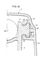
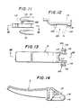
- a trigger type liquid dispenser of the second embodiment further comprises, in the first embodiment, a pair of opposed right and left lip-shaped engaging grooves 115 formed in section as shown in Fig. 10 on the inner surface 114 of the sidewall 110 of a body 6 as shown in Figs. 7, 8 and 10, 11, a pair of lugs 120 each having a base 118 and an end 119 of larger diameter than the base 118, projected perpendicularly to the trigger 3 oppositely from both lateral sides thereof at the fork portions 117 of the trigger 3 as shown in Figs. 13 and 14 in such a manner that the ends 119 of the lugs 120 are inserted into the spaces 121 of the grooves 115, respectively as shown in Fig.
- the bases 118 of the lugs 120 are disposed respectively in the spaces 122 formed at the fork portions 117 to be narrower than the spaces 121 of the grooves 115 of the body 6 and the ends 119 of the lugs 120 are rotatably restricted in the grooves 115 of the body 6.
- Projecting strips 128 shown in Figs. 8, 10 to 12 are projected on the inner surface of the sidewalls 110 of the body 6 at the position for holding the lugs 120 of the rotating trigger 3 at the longitudinal and lateral positions of the lugs 120 as shown in Fig. 12.
- the fork portions 117 are contacted with exhaust elements 109 irrespective of the rotation of the trigger 3.
- the lugs are not necessarily contacted inwardly due to the nozzle to prevent the fork portions of the trigger from being inwardly overturning irrespective of the rotation of the trigger so that the trigger can be rotatably restricted even during the temporary assembling work and after the assembling is completed.
- a third embodiment of a trigger type liquid dispenser according to the present invention will now be described.
- a trigger type liquid dispenser of this third embodiment having, as shown in Fig. 6, an exhaust cylindrical member 126 projected in a bore 125 surrounded by an upper wall 111, a left sidewall 112 and a right sidewall 113 of a body 6 and a piston unit 12 telescoped by a trigger 3 in the bore 125 comprises a guide rail 130 projected to arrive at the front end 116 of the body 6 in parallel with the exhaust cylindrical member 126 in the upper wall 111 as shown in Figs. 6 to 8, and engaging cylindrical portions 132 of the exhaust elements 109 are covered on the ends of the exhaust cylindrical members 126 as shown in Fig. 6.
- the exhaust elements 109 are formed in the shape as shown in Figs.
- a nozzle unit engaging cylindrical member 129 is projected to mount a nozzle unit 2 from which a nozzle 1 is projected, at the forward side of the flange 133.
- the guide rail of the body side is interposed to be held between the guide pieces of the exhaust element side in case of assembling to cover the exhaust cylindrical portion with the exhaust element as described above, the assembling position of the exhaust element is reliably established, the exhaust element can be thereafter readily and rapidly associated to cover the exhaust cylindrical portion to improve the assembling productivity.
- a fourth embodiment of a trigger type liquid dispenser according to the present invention will be described.
- the body 6 is mounted through a flange 17 of the intake inner cylindrical member 25 engaged with the mounting short cylindrical member 104, a packing 108 and a cap 30 at a liquid container, and the liquid in the liquid container is exhausted from the liquid container via a nozzle 1 through a dip tube 31, a ball valve 35, an exhaust valve body 40, an exhaust element 109 and a nozzle unit 2 by the operation of the piston unit 12 telescoped by the trigger 3 and the spring 20.
- the intake inner cylindrical member is inserted into the intake outer cylindrical member by engaging the extended cylindrical portion into the engaging annular cylindrical groove as described above in this embodiment, the possibility of leaking the liquid from a gap between the intake outer cylindrical member and the intake inner cylindrical member is much reduced as compared with a conventional liquid container in which the intake inner cylindrical member is merely engaged with the intake outer cylindrical member to entirely eliminate in fact the leakage of the liquid from the liquid container and to improve the liquid exhausting efficiency by the same trigger operation as the liquid dispenser.
- the cylinder of the pump is formed in double wall cylindrical members so that the inner cylindrical member forms therein the spring chamber and the atmospheric air is introduced into the spring chamber, the spring is not dipped in the exhausted liquid, the spring is not thus rusted nor dissolved in the liquid to eliminate a trouble caused by the spring.
- the skirts are formed at the sliding portions of the annular cylinder and the piston unit in these embodiments, separate seal is not necessarily provided to form the intake valve, the atmospheric air is supplied to the container as the piston unit is telescoped by the trigger to prevent the pumping efficiency from decreasing due to the negative pressure in the container, thereby entirely obviating the wasteful leakage of the exhaust liquid. Even if the liquid container is preserved or allowed to stand for a long period of time while the liquid container is mounted with the dispenser, no liquid is leaked from the container so that the dispenser can be readily and rapidly mounted on or dismounted from the liquid container.
Landscapes
- Closures For Containers (AREA)
- Containers And Packaging Bodies Having A Special Means To Remove Contents (AREA)
Applications Claiming Priority (8)
| Application Number | Priority Date | Filing Date | Title |
|---|---|---|---|
| JP1986111764U JPH0446844Y2 (fr) | 1986-07-21 | 1986-07-21 | |
| JP111764/86 | 1986-07-21 | ||
| JP1986203540U JPH064920Y2 (ja) | 1986-12-27 | 1986-12-27 | トリガ式液体噴出器 |
| JP203540/86 | 1986-12-27 | ||
| JP1987105112U JPH0716051Y2 (ja) | 1987-07-08 | 1987-07-08 | 液体吐出器のインテーク内筒体取付構造 |
| JP105113/87 | 1987-07-08 | ||
| JP1987105113U JPH0716052Y2 (ja) | 1987-07-08 | 1987-07-08 | 液体吐出器の吐出エレメントの取付構造 |
| JP105112/87 | 1987-07-08 |
Publications (3)
| Publication Number | Publication Date |
|---|---|
| EP0254505A2 true EP0254505A2 (fr) | 1988-01-27 |
| EP0254505A3 EP0254505A3 (en) | 1989-07-12 |
| EP0254505B1 EP0254505B1 (fr) | 1992-04-22 |
Family
ID=27469288
Family Applications (1)
| Application Number | Title | Priority Date | Filing Date |
|---|---|---|---|
| EP87306367A Expired EP0254505B1 (fr) | 1986-07-21 | 1987-07-17 | Distributeur de liquide du type à gâchette |
Country Status (4)
| Country | Link |
|---|---|
| US (1) | US4819835A (fr) |
| EP (1) | EP0254505B1 (fr) |
| AU (1) | AU608522B2 (fr) |
| DE (1) | DE3778441D1 (fr) |
Cited By (4)
| Publication number | Priority date | Publication date | Assignee | Title |
|---|---|---|---|---|
| US4958754A (en) * | 1989-03-01 | 1990-09-25 | Continental Sprayers, Inc. | Dispenser or sprayer with vent system |
| EP0441377A3 (en) * | 1990-02-09 | 1992-02-26 | Karl Klaeger | Manually operated sprayer for liquids |
| GB2259030A (en) * | 1991-06-07 | 1993-03-03 | Bristol Myers Squibb Co | A trigger spray |
| US5704521A (en) * | 1995-06-06 | 1998-01-06 | Calmar Inc. | Trigger actuated sprayer |
Families Citing this family (86)
| Publication number | Priority date | Publication date | Assignee | Title |
|---|---|---|---|---|
| US4917303A (en) * | 1988-09-26 | 1990-04-17 | Afa Products, Inc. | Snap-in trigger |
| US5062549A (en) * | 1989-11-03 | 1991-11-05 | Dowbrands Inc. | Hand held, dip-tube style liquid dispenser |
| US5385302A (en) * | 1990-10-25 | 1995-01-31 | Contico | Low cost trigger sprayer |
| US5232632A (en) * | 1991-05-09 | 1993-08-03 | The Procter & Gamble Company | Foam liquid hard surface detergent composition |
| USD337945S (en) | 1991-06-07 | 1993-08-03 | The Drackett Company | Trigger sprayer |
| US5549249A (en) * | 1991-12-13 | 1996-08-27 | Contico International, Inc. | Fluid spinner and nozzle head assembly with controlled fluid flood path |
| US5332128A (en) * | 1992-02-24 | 1994-07-26 | Afa Products, Inc. | Flap valve assembly for trigger sprayer |
| US5344053A (en) * | 1992-03-09 | 1994-09-06 | Contico International, Inc. | Trigger sprayer having a two-piece housing construction |
| EP0894539B1 (fr) | 1992-09-03 | 2002-06-05 | Yoshino Kogyosho Co., Ltd. | Piston de pompe pour pulvérisateur de liquide à gachette |
| US5464130A (en) * | 1992-09-03 | 1995-11-07 | Yoshino Kogyosho Co., Ltd. | Piston of pump section of trigger-type liquid dispenser |
| US5402916A (en) * | 1993-06-22 | 1995-04-04 | Nottingham Spirk Design Associates | Dual chamber sprayer with metering assembly |
| FR2711930B1 (fr) * | 1993-11-03 | 1996-01-26 | Sofab | Dispositif de pulvérisation. |
| US5670475A (en) * | 1994-08-12 | 1997-09-23 | The Procter & Gamble Company | Composition for reducing malodor impression of inanimate surfaces |
| US5663134A (en) * | 1994-08-12 | 1997-09-02 | The Procter & Gamble Company | Composition for reducing malodor impression on inanimate surfaces |
| US5578563A (en) * | 1994-08-12 | 1996-11-26 | The Procter & Gamble Company | Composition for reducing malodor impression on inanimate surfaces |
| US5939060A (en) * | 1994-08-12 | 1999-08-17 | The Procter & Gamble Company | Composition for reducing malodor impression on inanimate surfaces |
| US5593670A (en) * | 1994-08-12 | 1997-01-14 | The Proctor & Gamble Company | Uncomplexed cyclodextrin solutions for odor control on inanimate surfaces |
| US5714137A (en) * | 1994-08-12 | 1998-02-03 | The Procter & Gamble Company | Uncomplexed cyclodextrin solutions for odor control on inanimate surfaces |
| US5668097A (en) * | 1994-08-12 | 1997-09-16 | The Procter & Gamble Company | Uncomplexed cyclodextrin solutions for odor control on inanimate surfaces |
| US5534165A (en) * | 1994-08-12 | 1996-07-09 | The Procter & Gamble Company | Fabric treating composition containing beta-cyclodextrin and essentially free of perfume |
| RU2149025C1 (ru) | 1994-08-12 | 2000-05-20 | Дзе Проктер Энд Гэмбл Компани | Композиция для устранения неприятного запаха на поверхности предметов, промышленное изделие и способ обработки изделия или поверхности предметов |
| JP2892289B2 (ja) * | 1994-09-16 | 1999-05-17 | キャニヨン株式会社 | トリガ−タイプディスペンサ−およびそのための一方向弁 |
| DE69535779D1 (de) | 1994-10-26 | 2008-08-07 | Yoshino Kogyosho Co Ltd | Hebelbetätigte Flüssigkeitsaustragsvorrichtung |
| AU780401B2 (en) * | 1994-10-26 | 2005-03-17 | Yoshino Kogyosho Co., Ltd. | Trigger type liquid discharge device |
| DE69536103D1 (de) * | 1994-10-26 | 2010-10-21 | Yoshino Kogyosho Co Ltd | Flüssigkeitsentladungsvorrichtung mit Auslöser |
| US5532023A (en) * | 1994-11-10 | 1996-07-02 | The Procter & Gamble Company | Wrinkle reducing composition |
| WO1996015310A2 (fr) * | 1994-11-10 | 1996-05-23 | The Procter & Gamble Company | Composition attenuant les faux plis |
| US5779108A (en) * | 1995-06-15 | 1998-07-14 | Calmar Inc. | Pressure venting trigger sprayer |
| USD381581S (en) * | 1995-11-02 | 1997-07-29 | Calmar Inc. | Sprayer shroud |
| USD377602S (en) * | 1995-11-02 | 1997-01-28 | Calmar Inc. | Sprayer shroud |
| US5626259A (en) * | 1995-11-16 | 1997-05-06 | Afa Products, Inc. | Two liquid sprayer assembly |
| US5762236A (en) * | 1996-01-16 | 1998-06-09 | Contico International, Inc. | Trigger mechanism for trigger sprayer |
| US5716008A (en) * | 1996-03-04 | 1998-02-10 | Nottingham-Spirk Design Associates, Inc. | Trigger sprayer |
| US5752629A (en) * | 1996-04-12 | 1998-05-19 | The Procter & Gamble Company | Passive venting for pump dispensing device |
| US5806724A (en) * | 1996-06-04 | 1998-09-15 | Contico International, Inc. | Dispenser with improved bottle connection and method of making same |
| ID18608A (id) * | 1996-10-22 | 1998-04-23 | Yoshino Kogyosho Co Ltd | Dispenser cairan jenis-picu |
| US5875926A (en) * | 1996-11-26 | 1999-03-02 | The Procter & Gamble Company | Cylindrical barrel, linear, slide trigger |
| AU6954198A (en) * | 1997-04-08 | 1998-10-30 | Cigone Enterprises, Inc. | Method, composition, and system for removing odors |
| USD406762S (en) * | 1997-08-06 | 1999-03-16 | Owens-Illinois Closure, Inc. | Trigger pump dispenser shroud |
| USD442088S1 (en) | 2000-02-16 | 2001-05-15 | Owens-Illinois Closure Inc. | Trigger pump dispenser shroud |
| US6286727B1 (en) * | 2000-05-04 | 2001-09-11 | Owens-Illinois Closure Inc. | Pump dispenser having ergonomic overhang and method of making it |
| US6502766B1 (en) * | 2000-07-24 | 2003-01-07 | The Procter & Gamble Company | Liquid sprayers |
| US6752330B2 (en) | 2000-07-24 | 2004-06-22 | The Procter & Gamble Company | Liquid sprayers |
| US20030203035A1 (en) * | 2000-09-29 | 2003-10-30 | The Procter & Gamble Company | Allergen neutralization compositions |
| US20030206965A1 (en) * | 2000-09-29 | 2003-11-06 | The Procter & Gamble Company | Allergen neutralization compositions |
| US7645746B1 (en) | 2000-11-13 | 2010-01-12 | The Procter & Gamble Company | Composition for reducing malodor impression on inanimate surfaces |
| US7470277B2 (en) * | 2001-10-16 | 2008-12-30 | Alcon, Inc. | Simultaneous proportional control of surgical parameters in a microsurgical system |
| WO2016115408A1 (fr) | 2015-01-14 | 2016-07-21 | Gregory Van Buskirk | Procédé de traitement de tissu amélioré pour l'élimination des taches |
| US20030224030A1 (en) | 2002-05-23 | 2003-12-04 | Hirotaka Uchiyama | Methods and articles for reducing airborne particulates |
| BR0303954A (pt) * | 2002-10-10 | 2004-09-08 | Int Flavors & Fragrances Inc | Composição, fragrância, método para divisão de uma quantidade efetiva olfativa de fragrância em um produto sem enxague e produto sem enxague |
| US7585824B2 (en) | 2002-10-10 | 2009-09-08 | International Flavors & Fragrances Inc. | Encapsulated fragrance chemicals |
| US7318539B2 (en) * | 2003-04-28 | 2008-01-15 | Power Sprayer Llc | Pump drive unit for battery operated fluid dispensers |
| US20050113282A1 (en) * | 2003-11-20 | 2005-05-26 | Parekh Prabodh P. | Melamine-formaldehyde microcapsule slurries for fabric article freshening |
| US20050112152A1 (en) * | 2003-11-20 | 2005-05-26 | Popplewell Lewis M. | Encapsulated materials |
| US7105064B2 (en) * | 2003-11-20 | 2006-09-12 | International Flavors & Fragrances Inc. | Particulate fragrance deposition on surfaces and malodour elimination from surfaces |
| US7531365B2 (en) * | 2004-01-08 | 2009-05-12 | International Flavors & Fragrances Inc. | Analysis of the headspace proximate a substrate surface containing fragrance-containing microcapsules |
| USD541652S1 (en) | 2004-04-06 | 2007-05-01 | Arminak & Associates | Sprayer shroud |
| US20050226900A1 (en) * | 2004-04-13 | 2005-10-13 | Winton Brooks Clint D | Skin and hair treatment composition and process for using same resulting in controllably-releasable fragrance and/or malodour counteractant evolution |
| US20050227907A1 (en) * | 2004-04-13 | 2005-10-13 | Kaiping Lee | Stable fragrance microcapsule suspension and process for using same |
| US7354008B2 (en) * | 2004-09-24 | 2008-04-08 | Bowles Fluidics Corporation | Fluidic nozzle for trigger spray applications |
| US7306122B2 (en) * | 2004-10-08 | 2007-12-11 | Continental Afa Dispensing Company | Trigger sprayer venting system |
| US7311227B2 (en) * | 2004-10-08 | 2007-12-25 | Continental Afa Dispensing Company | Trigger sprayer venting system with reduced drag on vent piston |
| US7967171B2 (en) * | 2004-10-11 | 2011-06-28 | Meadwestvaco Calmar, Inc. | Air foaming pump trigger sprayer |
| US7594594B2 (en) | 2004-11-17 | 2009-09-29 | International Flavors & Fragrances Inc. | Multi-compartment storage and delivery containers and delivery system for microencapsulated fragrances |
| USD508852S1 (en) | 2004-11-24 | 2005-08-30 | Arminak & Associates, Inc. | Shroud |
| US20070207174A1 (en) * | 2005-05-06 | 2007-09-06 | Pluyter Johan G L | Encapsulated fragrance materials and methods for making same |
| EP2109661A1 (fr) * | 2007-02-09 | 2009-10-21 | The Procter & Gamble Company | Systèmes de parfums |
| US20090152270A1 (en) * | 2007-12-12 | 2009-06-18 | Thomas George Crowe | Orientation system for a closure |
| US9546274B2 (en) | 2009-05-26 | 2017-01-17 | The Armor All/Stp Products Company | Automotive protectant compositions with improved vertical cling |
| US10159997B2 (en) | 2009-11-30 | 2018-12-25 | Silgan Dispensing Systems Corporation | Low cost trigger sprayer |
| US8322631B2 (en) | 2010-05-10 | 2012-12-04 | The Procter & Gamble Company | Trigger pump sprayer having favorable particle size distribution with specified liquids |
| US8322630B2 (en) | 2010-05-10 | 2012-12-04 | The Procter & Gamble Company | Trigger pump sprayer |
| IT1401659B1 (it) * | 2010-09-16 | 2013-08-02 | Guala Dispensing Spa | Dispositivo di erogazione per liquidi |
| US8974589B2 (en) | 2010-10-25 | 2015-03-10 | The Armor All/Stp Products Company | Silicone protectant compositions |
| US9399722B2 (en) | 2011-03-31 | 2016-07-26 | The Armor All/Stp Products Company | Compositions and methods for treating automotive surfaces |
| US9546346B2 (en) | 2011-04-07 | 2017-01-17 | The Dial Corporation | Use of polyethylene glycol to control the spray pattern of sprayable liquid abrasive cleansers |
| ITMI20112168A1 (it) * | 2011-11-28 | 2013-05-29 | Mwv Vicenza S P A | Spruzzatore per liquidi con camera di precompressione |
| US9062282B2 (en) | 2012-10-15 | 2015-06-23 | Ecolab Usa Inc. | Leather and/or vinyl cleaner and moisturizer and method of making same |
| EP2978832A1 (fr) | 2013-03-26 | 2016-02-03 | The Procter & Gamble Company | Compositions de nettoyage destinées au nettoyage d'une surface dure |
| US20150104348A1 (en) | 2013-10-10 | 2015-04-16 | The Iams Company | Pet Deodorizing Composition |
| JP6208033B2 (ja) * | 2014-01-31 | 2017-10-04 | 株式会社吉野工業所 | トリガー式液体噴出器 |
| US20180303747A1 (en) * | 2017-04-20 | 2018-10-25 | Charlotte Higginbotham - Van Horn | Scalp relieving mixture and spray |
| US10441963B2 (en) * | 2018-01-30 | 2019-10-15 | The Procter & Gamble Company | Liquid dispensing product having a spray dispenser having a trigger lock |
| CN109326488A (zh) * | 2018-12-19 | 2019-02-12 | 成都洛的高新材料技术有限公司 | 一种水解式自溶延时触发器 |
| EP4161281A1 (fr) | 2020-06-07 | 2023-04-12 | Comestaag LLC | Compositions de revêtement protecteur pour denrées périssables et procédés, systèmes, kits et articles revêtus associés |
| CA3264864A1 (fr) | 2022-08-15 | 2024-02-22 | Energizer Auto, Inc. | Formulation de traitement de surface et son procédé de fabrication et d'utilisation |
Family Cites Families (10)
| Publication number | Priority date | Publication date | Assignee | Title |
|---|---|---|---|---|
| US3249259A (en) * | 1964-08-03 | 1966-05-03 | Calmar Inc | Reciprocating pump type dispenser |
| FR2320789A1 (fr) * | 1975-08-14 | 1977-03-11 | Pulverisation Step Ste Tech | Vaporisateur a precompression |
| IT1071471B (it) * | 1976-10-18 | 1985-04-10 | Spray Plast S R L | Spruzaztore manuale per liquidi |
| US4489861A (en) * | 1979-05-21 | 1984-12-25 | Yoshino Kogyosho Co., Ltd. | Manual liquid dispensing device |
| US4357798A (en) * | 1980-03-13 | 1982-11-09 | Michael Hung | Rapid actuating device of hydraulic actuator |
| US4424012A (en) * | 1981-10-09 | 1984-01-03 | Inotek-Westmoreland Venture | In-line fluid pump and shuttle valve therefor |
| US4527741A (en) * | 1983-06-13 | 1985-07-09 | The Afa Corporation | Trigger pump sprayer |
| US4596344A (en) * | 1983-10-07 | 1986-06-24 | Corsette Douglas Frank | Manually actuated dispenser |
| US4618077A (en) * | 1984-03-07 | 1986-10-21 | Corsette Douglas Frank | Liquid dispensing pump |
| US4669664A (en) * | 1984-04-09 | 1987-06-02 | Waynesboro Textiles, Inc. | Hand manipulatable sprayer |
-
1987
- 1987-07-17 EP EP87306367A patent/EP0254505B1/fr not_active Expired
- 1987-07-17 DE DE8787306367T patent/DE3778441D1/de not_active Expired - Fee Related
- 1987-07-17 US US07/074,727 patent/US4819835A/en not_active Expired - Lifetime
- 1987-07-21 AU AU75953/87A patent/AU608522B2/en not_active Ceased
Cited By (7)
| Publication number | Priority date | Publication date | Assignee | Title |
|---|---|---|---|---|
| US4958754A (en) * | 1989-03-01 | 1990-09-25 | Continental Sprayers, Inc. | Dispenser or sprayer with vent system |
| GB2232448B (en) * | 1989-03-01 | 1993-01-27 | Contico Int Inc | Dispenser or sprayer with vent system |
| EP0441377A3 (en) * | 1990-02-09 | 1992-02-26 | Karl Klaeger | Manually operated sprayer for liquids |
| GB2259030A (en) * | 1991-06-07 | 1993-03-03 | Bristol Myers Squibb Co | A trigger spray |
| AU659161B2 (en) * | 1991-06-07 | 1995-05-11 | Contico International, Inc. | Ergonomic trigger sprayer and hand positioner therefore |
| GB2259030B (en) * | 1991-06-07 | 1995-06-28 | Bristol Myers Squibb Co | Ergonomic trigger sprayer |
| US5704521A (en) * | 1995-06-06 | 1998-01-06 | Calmar Inc. | Trigger actuated sprayer |
Also Published As
| Publication number | Publication date |
|---|---|
| US4819835A (en) | 1989-04-11 |
| EP0254505B1 (fr) | 1992-04-22 |
| EP0254505A3 (en) | 1989-07-12 |
| DE3778441D1 (de) | 1992-05-27 |
| AU608522B2 (en) | 1991-04-11 |
| AU7595387A (en) | 1988-01-28 |
Similar Documents
| Publication | Publication Date | Title |
|---|---|---|
| EP0254505B1 (fr) | Distributeur de liquide du type à gâchette | |
| US4589573A (en) | Head depression type dispenser | |
| US4017031A (en) | Miniature atomizer of manual type | |
| US4462549A (en) | Manual type miniature atomizer | |
| EP0951944B1 (fr) | Pompe à membrane bombée pour distributeurs de liquide du type à gàchette | |
| US4317531A (en) | Accumulator type manual atomizer | |
| US3991914A (en) | Easily assembled, leakproof liquid dispensing pump | |
| KR920700779A (ko) | 액체 분출기 | |
| EP0062341A1 (fr) | Mécanisme de pompage à dispositif d'étanchéité | |
| JPH05139468A (ja) | 媒体用排出装置 | |
| US20050133541A1 (en) | Fluid dispenser member and a dispenser including such a member | |
| CA1291971C (fr) | Debiteur de liquide commande par gachette | |
| JP6816974B2 (ja) | 流路切替えアダプタ及び正倒立両用液体噴出ポンプ | |
| JP3901444B2 (ja) | オール樹脂ポンプ | |
| JPH0422861Y2 (fr) | ||
| JP4222464B2 (ja) | 液体噴出ポンプ | |
| JPH0615854Y2 (ja) | 縦型ポンプ式液体噴出容器 | |
| JPH0439191Y2 (fr) | ||
| JPH0754124Y2 (ja) | 縦型ポンプ式液体噴出容器 | |
| JPS6026840Y2 (ja) | 手動ポンプ式噴霧器 | |
| US20250135479A1 (en) | All-plastic perfume pump and bottle body used therefor | |
| JPS6026843Y2 (ja) | 手動式小型噴霧器 | |
| JPS6290766U (fr) | ||
| JPH0326920Y2 (fr) | ||
| JPH0414136Y2 (fr) |
Legal Events
| Date | Code | Title | Description |
|---|---|---|---|
| PUAI | Public reference made under article 153(3) epc to a published international application that has entered the european phase |
Free format text: ORIGINAL CODE: 0009012 |
|
| AK | Designated contracting states |
Kind code of ref document: A2 Designated state(s): CH DE FR GB IT LI NL |
|
| PUAL | Search report despatched |
Free format text: ORIGINAL CODE: 0009013 |
|
| AK | Designated contracting states |
Kind code of ref document: A3 Designated state(s): CH DE FR GB IT LI NL |
|
| 17P | Request for examination filed |
Effective date: 19891102 |
|
| 17Q | First examination report despatched |
Effective date: 19900918 |
|
| GRAA | (expected) grant |
Free format text: ORIGINAL CODE: 0009210 |
|
| AK | Designated contracting states |
Kind code of ref document: B1 Designated state(s): CH DE FR GB IT LI NL |
|
| ITF | It: translation for a ep patent filed | ||
| REF | Corresponds to: |
Ref document number: 3778441 Country of ref document: DE Date of ref document: 19920527 |
|
| ET | Fr: translation filed | ||
| PLBE | No opposition filed within time limit |
Free format text: ORIGINAL CODE: 0009261 |
|
| STAA | Information on the status of an ep patent application or granted ep patent |
Free format text: STATUS: NO OPPOSITION FILED WITHIN TIME LIMIT |
|
| 26N | No opposition filed | ||
| PGFP | Annual fee paid to national office [announced via postgrant information from national office to epo] |
Ref country code: CH Payment date: 20001010 Year of fee payment: 14 |
|
| PG25 | Lapsed in a contracting state [announced via postgrant information from national office to epo] |
Ref country code: LI Free format text: LAPSE BECAUSE OF NON-PAYMENT OF DUE FEES Effective date: 20010731 Ref country code: CH Free format text: LAPSE BECAUSE OF NON-PAYMENT OF DUE FEES Effective date: 20010731 |
|
| REG | Reference to a national code |
Ref country code: GB Ref legal event code: IF02 |
|
| REG | Reference to a national code |
Ref country code: CH Ref legal event code: PL |
|
| PGFP | Annual fee paid to national office [announced via postgrant information from national office to epo] |
Ref country code: FR Payment date: 20020709 Year of fee payment: 16 |
|
| PGFP | Annual fee paid to national office [announced via postgrant information from national office to epo] |
Ref country code: GB Payment date: 20020717 Year of fee payment: 16 |
|
| PGFP | Annual fee paid to national office [announced via postgrant information from national office to epo] |
Ref country code: DE Payment date: 20020724 Year of fee payment: 16 |
|
| PG25 | Lapsed in a contracting state [announced via postgrant information from national office to epo] |
Ref country code: GB Free format text: LAPSE BECAUSE OF NON-PAYMENT OF DUE FEES Effective date: 20030717 |
|
| PG25 | Lapsed in a contracting state [announced via postgrant information from national office to epo] |
Ref country code: DE Free format text: LAPSE BECAUSE OF NON-PAYMENT OF DUE FEES Effective date: 20040203 |
|
| GBPC | Gb: european patent ceased through non-payment of renewal fee |
Effective date: 20030717 |
|
| PG25 | Lapsed in a contracting state [announced via postgrant information from national office to epo] |
Ref country code: FR Free format text: LAPSE BECAUSE OF NON-PAYMENT OF DUE FEES Effective date: 20040331 |
|
| REG | Reference to a national code |
Ref country code: FR Ref legal event code: ST |
|
| PG25 | Lapsed in a contracting state [announced via postgrant information from national office to epo] |
Ref country code: IT Free format text: LAPSE BECAUSE OF NON-PAYMENT OF DUE FEES;WARNING: LAPSES OF ITALIAN PATENTS WITH EFFECTIVE DATE BEFORE 2007 MAY HAVE OCCURRED AT ANY TIME BEFORE 2007. THE CORRECT EFFECTIVE DATE MAY BE DIFFERENT FROM THE ONE RECORDED. Effective date: 20050717 |
|
| PGFP | Annual fee paid to national office [announced via postgrant information from national office to epo] |
Ref country code: NL Payment date: 20060716 Year of fee payment: 20 |
|
| PG25 | Lapsed in a contracting state [announced via postgrant information from national office to epo] |
Ref country code: NL Free format text: LAPSE BECAUSE OF EXPIRATION OF PROTECTION Effective date: 20070717 |
|
| NLV7 | Nl: ceased due to reaching the maximum lifetime of a patent |
Effective date: 20070717 |