EP0254904A2 - Cage de laminoir, en particulier pour laminer des bandes - Google Patents
Cage de laminoir, en particulier pour laminer des bandes Download PDFInfo
- Publication number
- EP0254904A2 EP0254904A2 EP87109587A EP87109587A EP0254904A2 EP 0254904 A2 EP0254904 A2 EP 0254904A2 EP 87109587 A EP87109587 A EP 87109587A EP 87109587 A EP87109587 A EP 87109587A EP 0254904 A2 EP0254904 A2 EP 0254904A2
- Authority
- EP
- European Patent Office
- Prior art keywords
- rolls
- work
- bale
- roll
- rolling
- Prior art date
- Legal status (The legal status is an assumption and is not a legal conclusion. Google has not performed a legal analysis and makes no representation as to the accuracy of the status listed.)
- Ceased
Links
Images


Classifications
-
- B—PERFORMING OPERATIONS; TRANSPORTING
- B21—MECHANICAL METAL-WORKING WITHOUT ESSENTIALLY REMOVING MATERIAL; PUNCHING METAL
- B21B—ROLLING OF METAL
- B21B13/00—Metal-rolling stands, i.e. an assembly composed of a stand frame, rolls, and accessories
- B21B13/14—Metal-rolling stands, i.e. an assembly composed of a stand frame, rolls, and accessories having counter-pressure devices acting on rolls to inhibit deflection of same under load; Back-up rolls
- B21B13/142—Metal-rolling stands, i.e. an assembly composed of a stand frame, rolls, and accessories having counter-pressure devices acting on rolls to inhibit deflection of same under load; Back-up rolls by axially shifting the rolls, e.g. rolls with tapered ends or with a curved contour for continuously-variable crown CVC
Definitions
- the invention relates to a rolling mill or rolling stand for the production of a rolling stock, in particular a rolling belt with work rolls, which are optionally supported on support rolls or intermediate rolls and support rolls, the work rolls and / or the support rolls and / or the intermediate rolls being axially displaceable relative to each other and each Roll at least one of these pairs of rolls is provided with a curved contour running in the direction of a bale end, which extends on the two rolls on opposite sides in each case over part of the width of the rolling stock, the curved contour extending over the entire bale length of both rolls and one Shape, in which the two bale contours complement each other in a certain relative axial position.
- a rolling mill of the same type is known, for example, from European Patent 0 049 798.
- the roll gap profile is to be influenced by means of the measures described there.
- a special position of the rollers in relation to the edges of the rolling stock is not provided.
- the work rolls are generally supported along their entire length on intermediate or back-up rolls, so that those exerted by the back-up rolls Rolling force is also transmitted over its entire length. This has the consequence that the ends of the work rolls projecting laterally over the rolling stock and thus not participating in the rolling process are bent in the direction of the rolling stock by the rolling force exerted on them. In the case of roll stands with rigid work rolls, this harmful deflection of the work rolls manifests itself in the bending of their middle roll sections and causes the central strip area to be rolled out too little and the roll strip edges to be rolled out too much. These effects are particularly noticeable when the rolling conditions change during operation, such as strip temperature and rolling force, and when rolling strips of different widths.
- the object of the invention is to compensate for the disadvantageous deflection of the work rolls under rolling force over the entire range from small to large rolling stock width and to increase the roll bending effect of the roll bending devices without having to interrupt the rolling operation. Furthermore should the necessary displacement distances are shortened.
- the work rolls each have a curved contour tapering towards one end of the bale and widening towards the other end of the bale, and are arranged so as to be adjustable in opposite directions in the axial direction in such a way that the tapered end of a work roll between each a rolled edge and the end of the associated support roller is held.
- the bulbous parts of both work rolls advantageously cooperate in such a way that the tapered sections of the bulbous contours are arranged in the region of the two edges of the rolling stock.
- the work rolls with respect to the axial direction have a curved contour consisting of an approximately concave and an approximately convex part.
- intermediate rolls with an equally curved contour can advantageously be provided, which are arranged in opposite directions in the axial direction as the work rolls, in such a way that one end of an intermediate roll is held in the region of an edge of the rolling stock.
- cooperating work and intermediate rolls can expediently be aligned on opposite edges of the rolling stock.
- the work rolls are cylindrical or symmetrically spherical and the intermediate rolls each have a curved contour tapering towards one end of the bale and widening towards the other end of the bale and are arranged so as to be adjustable in opposite directions in the axial direction, that in each case the tapered end of an intermediate roller is held between an edge of the rolling stock and the end of the associated support roller.
- the necessary displacement paths can be reduced by up to 60% with the same effect depending on the strip width and rolling force.
- the intermediate rollers can have a curved contour with respect to the axial direction and consist of an approximately concave and an approximately convex part, the end of each intermediate roller being aligned and held on an edge of the rolling stock. With this axial position of the rollers, the tapered parts of both intermediate rollers act simultaneously on each edge of the rolling stock, as a result of which the load distribution in the edge region of the rolling stock is particularly favorable.
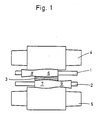
- two work rolls (1) and (2) which are arranged vertically one above the other and which directly roll a rolling stock (3), are held in a known manner by chocks (not shown) mounted in roll stands.
- the work rolls (1, 2) are each supported by an upper and lower support roll (4, 5).
- Each of the work rolls (1, 2) is tapered at one end, ie the end (6) of the work roll (1) and the other end (7) of the work roll (2) have a bulbous shape tapering towards the end of the bale, while their opposite ends (8, 9) form the complementary addition.
- Such a grinding of the work rolls (1, 2) can also be referred to as an S-shape.
- the work rolls (1, 2) have pins at one end, to which couplings for connecting drive devices (not shown) are attached.
- the respectively tapering ends (6, 7) of the work rolls (1, 2) are arranged in the region of the edges of the rolled strip (3) by axial displacement. In this arrangement, strong rolling pressures on the edges of the rolling stock (3) are largely avoided. If the rolling stock width changes, a sufficient cross-sectional constancy of the strip can be achieved by merely shifting the work rolls in the axial direction by means of the shift drives (not shown) via couplings, so that the tapered ends (6, 7) of these rolls are placed in the area of one rolled material edge.
- FIG. 2 shows two cylindrical work rolls (10) and (11) arranged vertically one above the other, which roll the rolling stock (12) and in turn are held in a known manner by chocks (not shown) mounted in roll stands.
- the two intermediate rolls (13, 14), each supported on a work roll (10, 11), are arranged in such a way that their axes lie essentially vertically above or below the axes of the work rolls.
- the intermediate rollers (13, 14) are supported by an upper and lower support roller (15, 16). Furthermore, each of the intermediate rolls (13, 14) is tapered at one end, i.e.
- the end (20) of the intermediate roller (13) and the other end (21) of the intermediate roller (14) have a bulbous shape which tapers towards the end of the bale, while the opposite ends (22, 23) form the complementary addition thereto.
- the intermediate rollers (13, 14) have pins at one of their ends, on which couplings for connecting drive devices (not shown) are attached.
- FIG. 3 shows two work rolls (30) and (31) arranged vertically one above the other but contoured.
- the intermediate rolls (33, 34), which are supported on each work roll (30, 31), are arranged in such a way that their axes in turn lie essentially vertically above or below the axes of the work rolls.
- the intermediate rollers (33, 34) are supported by an upper and lower backup roller (35, 36).
- each of the work and intermediate rolls (30, 31; 33, 34) is tapered at one end, the ends (40, 41, 42, 43) having the bulbous shape tapering towards the end of the bale, while their opposite ends ( 44, 45, 46, 47) form the respective complementary supplement.
- the work and intermediate rolls (30, 31; 33, 34) have pins at one end, on which couplings for connecting drive devices (not shown) are attached.
Landscapes
- Engineering & Computer Science (AREA)
- Mechanical Engineering (AREA)
- Metal Rolling (AREA)
- Reduction Rolling/Reduction Stand/Operation Of Reduction Machine (AREA)
- Casting Or Compression Moulding Of Plastics Or The Like (AREA)
Applications Claiming Priority (2)
| Application Number | Priority Date | Filing Date | Title |
|---|---|---|---|
| DE3624241A DE3624241C2 (de) | 1986-07-18 | 1986-07-18 | Verfahren zum Betrieb eines Walzwerkes zur Herstellung eines Walzbandes |
| DE3624241 | 1986-07-18 |
Publications (2)
| Publication Number | Publication Date |
|---|---|
| EP0254904A2 true EP0254904A2 (fr) | 1988-02-03 |
| EP0254904A3 EP0254904A3 (fr) | 1989-04-19 |
Family
ID=6305423
Family Applications (1)
| Application Number | Title | Priority Date | Filing Date |
|---|---|---|---|
| EP87109587A Ceased EP0254904A3 (fr) | 1986-07-18 | 1987-07-03 | Cage de laminoir, en particulier pour laminer des bandes |
Country Status (7)
| Country | Link |
|---|---|
| US (1) | US4798074A (fr) |
| EP (1) | EP0254904A3 (fr) |
| JP (1) | JPH07115049B2 (fr) |
| CN (1) | CN1016588B (fr) |
| DE (1) | DE3624241C2 (fr) |
| RU (1) | RU2050994C1 (fr) |
| UA (1) | UA26059A1 (fr) |
Cited By (3)
| Publication number | Priority date | Publication date | Assignee | Title |
|---|---|---|---|---|
| DE3638331A1 (de) * | 1986-11-10 | 1988-05-19 | Schloemann Siemag Ag | Walzgeruest zum walzen von flachmaterial mit einem paar von axial verschiebbaren arbeitswalzen |
| GB2222376A (en) * | 1988-08-29 | 1990-03-07 | Sendzimir Inc T | Roll for cold rolling of metal strip |
| EP2017017A4 (fr) * | 2006-05-09 | 2012-07-11 | Jp Steel Plantech Co | Cylindre de laminage, laminoir et procede de laminage |
Families Citing this family (16)
| Publication number | Priority date | Publication date | Assignee | Title |
|---|---|---|---|---|
| JPH0763737B2 (ja) * | 1988-05-11 | 1995-07-12 | 日新製鋼株式会社 | ワークロールと接する中間ロール及びそれが組み込まれた多段圧延機 |
| US5218852A (en) * | 1989-06-05 | 1993-06-15 | Kawasaki Steel Corporation | Multi-roll cluster rolling apparatus |
| JP3174457B2 (ja) * | 1994-05-17 | 2001-06-11 | 株式会社日立製作所 | 連鋳直結熱間圧延設備およびその圧延方法 |
| TW358758B (en) * | 1996-12-27 | 1999-05-21 | Hitachi Ltd | Rolling mill and method of the same |
| JP3747786B2 (ja) † | 2001-02-05 | 2006-02-22 | 株式会社日立製作所 | 板材用圧延機の圧延方法及び板材用圧延設備 |
| DE10359402A1 (de) * | 2003-12-18 | 2005-07-14 | Sms Demag Ag | Optimierte Verschiebestrategien als Funktion der Bandbreite |
| CA2568829C (fr) * | 2004-09-14 | 2012-03-27 | Sms Siemag Aktiengesellschaft | Cylindre convexe destine a influencer le profil et la planeite d'une bande laminee |
| US8607848B2 (en) * | 2008-08-05 | 2013-12-17 | Nucor Corporation | Method for casting metal strip with dynamic crown control |
| US8607847B2 (en) * | 2008-08-05 | 2013-12-17 | Nucor Corporation | Method for casting metal strip with dynamic crown control |
| AT509107B1 (de) | 2009-12-10 | 2011-09-15 | Siemens Vai Metals Tech Gmbh | Walzgerüst zur herstellung von walzband |
| US9021706B2 (en) * | 2010-02-01 | 2015-05-05 | The Timken Company | Unified rolling and bending process for roller bearing cages |
| US8505611B2 (en) | 2011-06-10 | 2013-08-13 | Castrip, Llc | Twin roll continuous caster |
| DE102010049068A1 (de) * | 2010-10-20 | 2012-04-26 | Mtu Aero Engines Gmbh | Vorrichtung zum Herstellen, Reparieren und/oder Austauschen eines Bauteils mittels eines durch Energiestrahlung verfestigbaren Pulvers, sowie ein Verfahren und ein gemäß dem Verfahren hergestelltes Bauteil |
| CN102441574B (zh) * | 2011-09-22 | 2013-12-18 | 常州宝菱重工机械有限公司 | 四六辊互换轧机的托轴架装置 |
| CN109500082B (zh) * | 2018-12-27 | 2023-11-21 | 中冶南方工程技术有限公司 | 一种六辊轧机及其轧制控制方法 |
| CN115990616B (zh) * | 2023-03-23 | 2023-06-30 | 首钢智新迁安电磁材料有限公司 | 一种连轧机组及其窜辊值的控制方法 |
Family Cites Families (13)
| Publication number | Priority date | Publication date | Assignee | Title |
|---|---|---|---|---|
| US2732591A (en) * | 1956-01-31 | whittum | ||
| GB1351074A (en) * | 1971-02-15 | 1974-04-24 | Hitachi Ltd | Rolling mills |
| JPS517635B2 (fr) * | 1971-12-10 | 1976-03-09 | ||
| JPS6018243B2 (ja) * | 1980-07-07 | 1985-05-09 | 株式会社日立製作所 | 圧延ロ−ル |
| DE3038865C1 (de) * | 1980-10-15 | 1982-12-23 | SMS Schloemann-Siemag AG, 4000 Düsseldorf | Walzgeruest mit axial verschiebbaren Walzen |
| DE3213496A1 (de) * | 1982-04-10 | 1983-10-20 | SMS Schloemann-Siemag AG, 4000 Düsseldorf | Walzgeruest mit axial verschiebbaren walzen |
| US4519233A (en) * | 1980-10-15 | 1985-05-28 | Sms Schloemann-Siemag Ag | Roll stand with noncylindrical rolls |
| DE3245090A1 (de) * | 1982-12-06 | 1984-06-07 | SMS Schloemann-Siemag AG, 4000 Düsseldorf | Verfahren und einrichtung zum walzen von metallbaendern |
| JPS59110401A (ja) * | 1982-12-14 | 1984-06-26 | Ishikawajima Harima Heavy Ind Co Ltd | 圧延方法 |
| DE3325823A1 (de) * | 1983-07-18 | 1985-01-31 | SMS Schloemann-Siemag AG, 4000 Düsseldorf | Walzgeruest mit axial verschiebbaren arbeitswalzen |
| JPS6036330A (ja) * | 1983-08-10 | 1985-02-25 | Onoda Cement Co Ltd | 高純度酸化ジルコニウム微粉の製造方法 |
| US4683744A (en) * | 1985-06-18 | 1987-08-04 | Wean United Rolling Mills, Inc. | Flexible edge roll |
| US4656859A (en) * | 1985-08-21 | 1987-04-14 | Wean United, Inc. | Rolling mill stand employing variable crown rolls and associated method |
-
1986
- 1986-07-18 DE DE3624241A patent/DE3624241C2/de not_active Expired - Lifetime
-
1987
- 1987-06-15 JP JP62147182A patent/JPH07115049B2/ja not_active Expired - Lifetime
- 1987-07-03 EP EP87109587A patent/EP0254904A3/fr not_active Ceased
- 1987-07-17 RU SU874202940A patent/RU2050994C1/ru active
- 1987-07-17 UA UA4202940A patent/UA26059A1/uk unknown
- 1987-07-18 CN CN87104310A patent/CN1016588B/zh not_active Expired
- 1987-07-20 US US07/075,376 patent/US4798074A/en not_active Expired - Lifetime
Cited By (4)
| Publication number | Priority date | Publication date | Assignee | Title |
|---|---|---|---|---|
| DE3638331A1 (de) * | 1986-11-10 | 1988-05-19 | Schloemann Siemag Ag | Walzgeruest zum walzen von flachmaterial mit einem paar von axial verschiebbaren arbeitswalzen |
| GB2222376A (en) * | 1988-08-29 | 1990-03-07 | Sendzimir Inc T | Roll for cold rolling of metal strip |
| GB2222376B (en) * | 1988-08-29 | 1993-04-07 | Sendzimir Inc T | Apparatus and method for cold rolling of metal strip |
| EP2017017A4 (fr) * | 2006-05-09 | 2012-07-11 | Jp Steel Plantech Co | Cylindre de laminage, laminoir et procede de laminage |
Also Published As
| Publication number | Publication date |
|---|---|
| JPS6330104A (ja) | 1988-02-08 |
| CN87104310A (zh) | 1988-02-03 |
| EP0254904A3 (fr) | 1989-04-19 |
| DE3624241C2 (de) | 1996-07-11 |
| JPH07115049B2 (ja) | 1995-12-13 |
| DE3624241A1 (de) | 1988-01-28 |
| RU2050994C1 (ru) | 1995-12-27 |
| US4798074A (en) | 1989-01-17 |
| UA26059A1 (uk) | 1999-04-30 |
| CN1016588B (zh) | 1992-05-13 |
Similar Documents
| Publication | Publication Date | Title |
|---|---|---|
| EP0254904A2 (fr) | Cage de laminoir, en particulier pour laminer des bandes | |
| EP0049798B1 (fr) | Laminoir | |
| EP0249801B1 (fr) | Laminoir pour la fabrication d'un feuillard de laminage | |
| DE2260256C3 (de) | Walzgerüst | |
| DE3873103T2 (de) | Metallwalzverfahren mit in axialrichtung verschiebbaren arbeitswalzen. | |
| DE2206912C3 (de) | Walzgerüst | |
| EP0258482B1 (fr) | Cage de laminoir à cylindres déplaçables axialement | |
| EP0059417A1 (fr) | Cage de laminoir | |
| EP0876857A2 (fr) | Procédé pour influencer le profil dans la zone des bords d'une bande laminée | |
| DE2919105A1 (de) | Walzwerk | |
| EP2392416B1 (fr) | Cylindre d'appui et cage de laminoir en étant équipée | |
| EP0899029B1 (fr) | Cage de laminoir pour le laminage de bandes | |
| EP2509723B1 (fr) | Cage de laminoir pour fabriquer du ruban de laminage | |
| DE2341768A1 (de) | Walzgeruest | |
| EP0255714A2 (fr) | Laminoir à cylindres multiples avec des cylindres intermédiaires déplaçables axialement et aux extrémités coniques | |
| DE3919285A1 (de) | Vorrichtung und verfahren zum kaltwalzen eines metallbandes | |
| DE2335809C2 (de) | Walzgerüst | |
| EP0102014B1 (fr) | Cage de laminoir pour le laminage de feuillard à largeur différente | |
| DE2819567C2 (de) | Walzstraße zum Walzen von stabförmigem Gut | |
| DE3819303C2 (fr) | ||
| EP0181474A2 (fr) | Cage de laminoir à six cylindres | |
| DE3736683C2 (de) | Mehrrollen-Walzgerüst | |
| DE1251260B (de) | Stützwalzenanordnung zur Aufnahme des Walzdrucks der Arbeitswalzen eines Blechbandwalzwerks | |
| DE4030047C1 (fr) | ||
| DE2832049A1 (de) | Walzwerkgeruest |
Legal Events
| Date | Code | Title | Description |
|---|---|---|---|
| PUAI | Public reference made under article 153(3) epc to a published international application that has entered the european phase |
Free format text: ORIGINAL CODE: 0009012 |
|
| 17P | Request for examination filed |
Effective date: 19870714 |
|
| AK | Designated contracting states |
Kind code of ref document: A2 Designated state(s): AT BE DE ES FR GB IT NL SE |
|
| PUAL | Search report despatched |
Free format text: ORIGINAL CODE: 0009013 |
|
| AK | Designated contracting states |
Kind code of ref document: A3 Designated state(s): AT BE DE ES FR GB IT NL SE |
|
| 17Q | First examination report despatched |
Effective date: 19900423 |
|
| STAA | Information on the status of an ep patent application or granted ep patent |
Free format text: STATUS: THE APPLICATION HAS BEEN REFUSED |
|
| 18R | Application refused |
Effective date: 19910920 |
|
| APAF | Appeal reference modified |
Free format text: ORIGINAL CODE: EPIDOSCREFNE |
|
| RIN1 | Information on inventor provided before grant (corrected) |
Inventor name: BEISEMANN, GERD Inventor name: GAERTNER, HORST Inventor name: FELDMANN, HUGO, DR. Inventor name: HOLLMANN, FRIEDRICH, DR. |